
Numerical investigation on vibration isolation by softer in-filled trench barriers
Abstract
This paper deals with a 2-D finite element study in PLAXIS 2D on isolation of steady-state surface vibrations by softer backfilled trenches in an elastic, isotropic, and homogeneous half-space. Effects of barrier geometric features and infill material characteristics on reducing vertical and horizontal components of surface displacements are investigated. This study adopts a non-dimensional approach where the geometric parameters are normalized against the Rayleigh wavelength of vibration in half-space and backfill shear wave velocity is expressed as a ratio of that of parent soil. Softer barriers of shear wave velocity ratios less than unity are considered as they are found significantly effective than stiffer barriers. Effects of the parameters participating on wave isolation are extensively discussed and some guidelines are framed regarding their optimal selection. Non-dimensional charts are developed which would provide a sound basis for designing such barriers in actual engineering practice. The design charts are validated with some documented results and close agreement is obtained.
1Introduction
Other than earthquakes, ground vibrations are generated from a number of sources like vibrating machines, traffic, construction activities etc. Excessive ground vibrations, if not properly screened off, may cause malfunctioning of high-precision instruments, annoyance, and fatigue of structures. Vibration isolation measures, in general, consist of constructing barriers across the path of propagation of surface waves which sufficiently reduce the amplitude of incident waves. Open and in-filled trenches, solid or tubular piles, sheet piles etc. are typical examples of such barriers. When the barrier is placed in proximity to the source of excitation, the isolation scheme is termed as active isolation; whereas in passive isolation the barrier is located far-off from the source or in the vicinity of the target/site to be protected. In vibration isolation schemes, reduction of Rayleigh wave amplitude is primarily targeted since it carries nearly two-thirds of the total vibration energy and propagates exclusively within a zone close to the ground surface [1]. The other two types of seismic waves are body waves, i.e. compression and shear waves that carry only one-third of the total vibration energy and propagate in to the half-space. Rayleigh waves are also characterized by the largest amplitude among all seismic waves and much slower amplitude attenuation with distance than body waves.
Starting with the experimental investigation of Woods [1] on surface wave screening by open trenches, extensive research has been conducted so far in the field of wave barrier isolation. Many studies adopted numerical approaches owing to the fact that field experiments inherits sub-soil stratification problem which makes it difficult to draw generalized conclusions. Moreover, the number of cases that can be investigated with a numerical approach is almost impractical with full-scale experiments. Likewise, replicating the semi-infinite condition, which is difficult in small-scale model tests, can be well tackled by numerical methods. Beskos et al. [2], Dasgupta et al. [3], and Leung et al. [4] studied vibration isolation by open and in-filled trenches, respectively in two-dimensional (2-D), three-dimensional (3-D), and 2-D layered half-spaces using boundary element method. Simplified design of open and in-filled trenches [5], on wave barriers made of solid obstacles in reducing horizontal surface vibrations [6], active isolation of machine foundations using open and in-filled trenches [7, 8], vibration screening effectiveness of open trenches in a 3-D half-space [9] are subsequent boundary element studies in the domain. All these works primarily focused on open or concrete-filled trenches except Al-Hussaini and Ahmad [8], where some aspects of softer backfilled trenches were investigated.
Shrivastava and Rao [10] employed finite element method to investigate the effectiveness of open and in-filled trenches in isolating impulse loads. Yang and Hung [11] studied train-induced vibration isolation using open/in-filled trenches and elastic foundations adopting 2-D finite element scheme with infinite elements at boundaries. Reduction of train-induced vibration using open/in-filled trenches by Hung et al. [12], using open/in-filled trenches and ground improvement methods by Ju [13], and using open trenches by Di Mino et al. [14] are few more examples of barrier isolation studies. Adam and Estorff [15] studied the isolation of train-induced building vibrations by open and in-filled trenches employing a coupled boundary element and finite element algorithm. El Naggar and Chehab [16] conducted 2-D finite element study on reducing shock-induced vibrations by soft and stiff barriers.
Centrifuge model tests on geofoam barriers [17], full-scale experimentation on geofoam and open trenches [18], isolation effectiveness water-filled trenches in a 3-D half-space [19], on the analysis and design of open trenches by Babu et al. [20] are some contemporary studies in this field. Literatures of Turan et al. [21] on inclined secant micro-pile walls as active isolation measures, Leonardi and Buonsanti [22] on concrete trenches and compacted soil wave barriers, Hasheminezhad [23] on trench barriers filled with pipes, Ekanayake et al. [24] on water-filled and geofoam trenches, are few recent contributions based on finite element approach. However, these literatures have little relevance to the current context and cannot be considered within the scope of this study.
With few exceptions, majority of the previous works focused on stiffer backfilled (concrete-filled) trenches. Concerning softer barrier isolation, an effort was made by Al-Hussaini and Ahmad [8] but its scope is limited to the case of vertical vibration isolation in active scheme. In a recent 2-D finite element study [25] on barrier isolation, softer barriers are shown to provide better isolation effectiveness than stiffer barriers. The optimized design methodology proposed in this literature, however, requires a lot of computational time and programming skill. On the other hand, much simpler guidelines can be contributed in the form of non-dimensional design charts. In some earlier studies [11, 15, 16, 26], few aspects of softer backfilled trenches are addressed. Nevertheless, these literatures do not provide a comprehensive understanding on softer barrier isolation. Moreover, none of the previous literatures, other than Al-Hussaini and Ahmad [8], made any effort to constitute simplified design guidelines on such barriers. These pin-points the necessity of a further study on softer barrier isolation to establish the effects of various parameters, so as to frame some generalized design principles on such barriers.
This study investigates isolation effectiveness of softer in-filled trenches with respect to the variations in barrier geometric features and backfill material parameters. A non-dimensional approach is adopted by normalizing the geometric features against the Rayleigh wavelength of vibration in half-space. The shear wave velocity of backfill is expressed as a ratio to that of parent soil. Unlike many previous studies, where only the vertical component of vibration is mostly studied, amplitude reduction of both vertical and horizontal components of vibration is investigated in this work. Non-dimensional design charts are developed for application of such barriers in practice. The design charts are validated with some previously published results and close agreement is obtained.
2Methodology
The problem is viewed in this study from a 2-D perspective. In wave barrier isolation studies, realistic 3-D cases are often analyzed with 2-D slices assigning the same material properties. When the barrier length (dimension perpendicular to the plane of the paper) is large enough compared to its width and the study is restricted to the centerline of the barrier, the problem essentially reduces to a 2-D scenario. Accuracy of 2-D analyses over realistic 3-D models and experimental results has been manifested in several literatures [3, 15, 18, 26, 27].
2.1Basic assumptions
The half-space elastic parameters are assigned in accordance with Yang and Hung [11], assuming the elastic modulus (E), density (ρ), Poisson’s ratio (ν), and material damping (ξ) as 46000 kN/m2, 1800 kg/m3, 0.25, and 5%. A sinusoidally varying load of magnitude unity (P0= 1 kN) and frequency of excitation (f) 31 Hz is assumed to act uniformly over an imaginary footing of width, B = 1.0 m. Footing mass is not taken into consideration as the effect of footing mass on isolation effectiveness of a barrier is found insignificant [2]. The dynamic load parameters are assumed on the basis of Yang and Hung [11].
Against the assumed half-space parameters and excitation frequency, the shear wave velocity (Vs), Rayleigh wave velocity (VR), and Rayleigh wavelength (LR =VR/f) of half-space are estimated to be 101.1 m/s, 93.02 m/s, and 3 m respectively. The density (ρb), Poisson’s ratio (vb), and material damping (ξb) of backfill is assumed to be 1500 kg/m3, 0.25, and 5% respectively, while its elastic modulus (Eb) is treated as variable.
2.2Non-dimensional study scheme
Barrier geometric features are normalized against the Rayleigh wavelength of vibration in half-space to avoid dependency on the excitation frequency and half-space parameters. The geometric parameters, i.e. barrier distance from source (l), its depth (d), and width (w) are expressed in terms of Rayleigh wavelength as: l = L·LR, d = D·LR, and w = W·LR as depicted in Fig. 1. Here, L, D, and W are dimensionless quantities and respectively denotes distance of the barrier from source, its depth, and width; normalized against the Rayleigh wavelength.
Material damping of backfill is considered identical to that of half-space as isolation response is found unaffected due to the variations in material damping of backfill with respect to the parent soil [5, 11]. The shear wave velocity is a function of elastic modulus, density, and Poisson’s ratio, implying that variations of any of these parameters would bring about a change in shear wave velocity. A parameter called shear wave velocity ratio (Vb/Vs) is, therefore, used to investigate the effect of backfill material characteristics. A barrier softer than the surrounding soil will have Vb/Vs less than unity. For instance, Vb/Vs = 0.2 signifies that the backfill shear wave velocity (Vb) is 0.2 times of that of the half-space. Backfill shear wave velocity is varied by altering its elastic modulus, keeping other parameters same.
2.3Finite element modeling scheme
The study is performed in PLAXIS 2D with 2-D axisymmetric finite element models of dimension 35 m ×15 m discretized with fifteen noded triangular mesh elements. A zone extending to a distance of 10LR from source is indicated to be sufficient for wave barrier analyses [11, 16]. Against a Rayleigh wavelength, LR = 3 m in the current context, this crucial zone extends to 30 m from source. The reason behind adopting somewhat higher model length is to avoid any likelihood of interference problem which could arise due to wave reflection at boundaries. The adequacy of model dimension is affirmed by convergence studies by subjecting an undisturbed half-space (assigning the assumed soil parameters and boundary conditions) to a steady-state excitation of stated magnitude and frequency. Repeated trials are made on models of different dimensions and based on the convergence of the plots between peak particle displacements and distance from source, a dimension of 35 m ×15 m is finallyadopted.
The model boundaries are assigned to standard fixities that imposes horizontal fixities (ux = 0) to the symmetry edge and right hand boundary and total fixities (ux = uy=0) to the bottom boundary. The bottom and right hand model boundaries are subjected to special absorbent boundary conditions available in PLAXIS to allow for absorption of dynamic stresses. Absorbent boundaries are created with Lysmer and Kuhlemeyer [28] dampers and on the basis of previous study [29], the wave relaxation coefficients assigned to these boundaries for reasonable absorption of compression and shear waves are taken as, C1 = 1 and C2 = 0.25. The convergence studies also justify that the wave relaxation coefficients assigned to the absorbent boundaries allow for sufficient waveabsorption.
Linear elastic material model is used for modelling soil and backfill clusters considering the material type as drained. Material damping is assigned to half-space and backfill by introducing Rayleigh mass and stiffness matrix coefficients (α and β). The mesh division is done using very fine elements with local refinements along the surface and in backfill cluster. Use of local refinement tool enables further sub-division of mesh elements ensuring higher degree of precision. A steady-state excitation of magnitude 1 kN/m and frequency 31 Hz is applied over one-half of the assumed footing width as axisymmetric models are used. A time interval (Δt) of 0.5 s. is chosen for the dynamic analyses and computations are done in 1000 steps in total, keeping the time-step of integration (δt) as 0.0005 s. Chosen time interval is sufficient to permit the complete transit of dynamic disturbance in the zone of investigation. Peak surface displacement amplitudes are estimated from displacement-time histories at pre-selected nodes in intervals of 0.5LR beyond the barrier. A typical finite element model showing generated mesh, dimensions and boundary conditions etc. is presented in Fig. 2.
Current modelling scheme is validated with reference to an isolation example by an open trench of dimension, D = 1, W = 0.1, and L = 5. Amplitude reduction factors at different distances from source are found to be in excellent agreement with published works [5, 14]. Readers may refer to author’s previous works [30, 31] for material parameter assumptions, convergence studies, finite element modelling and validation.
2.4Degree of isolation
Barrier isolation effectiveness is assessed in terms of amplitude reduction factor (AR) which is defined as the ratio between surface displacements amplitudes with and without barrier [1]. The overall degree of isolation over a zone of study (s) is expressed in terms of average amplitude reduction factor (Am) as AR values are not uniform throughout the zone. Am is defined as the weighted average of the AR values measured at different distances from source (x) over the zone of interest. Lesser value of Am indicates a better screening effect.
(1)
(2)
3Parametric study: Results and discussion
In order to perform a dimensionless parametric study, the geometric features are expressed in terms of Rayleigh wavelength and backfill material parameters in terms of backfill shear wave velocity ratios as discussed in Section 2.2. In the subsequent sections, notations Uy and Ux are used to denote the vertical and horizontal vibration components, while Amy and Amx refers to the average amplitude reduction factors of the respective components. Other notations have their usual meanings as previously explained.
As already stated, the geometric features and backfill shear wave velocity ratio are the parameters that govern the isolation effectiveness of an in-filled trench. Effects of these parameters are discussed in the following sub-sections (Section 3.1 to 3.3). However, in the following sections other than Section 3.1, softer wave barriers characterized by shear wave velocity ratios less than unity are considered as they are found significantly effective than stiffer barriers. Non-dimensional design charts are presented in Section 3.4 for active and passive isolation by softer barriers. In Section 3.5, the design charts are validated with some published results of softer barrier isolation.
3.1Effect of shear wave velocity ratio
Although, it has been manifested that softer barriers are better isolators than stiffer ones [8, 15, 16, 25], few such cases are investigated justifying the choice of softer barriers in this study. The trenches are assumed to have a specific depth (D = 1) and location (L = 5) and widths, W = 0.3 and 0.5. The backfill shear wave velocity ratio is varied from 0.1 to 0.7 for softer barriers and 2 to 8 in case of stiffer barriers. The backfill shear wave velocity is varied by changing its elastic modulus keeping other parameters unaltered. Effect of Vb/Vs on Amy and Amx are depicted in Fig. 3. It is evident that the backfill must differ from the half-space in terms of shear wave velocities to cause vibration attenuation. This implies that the backfill should have either lower or higher shear wave velocities than the parent soil. The amplitude reduction curves would reach unity irrespective of the trench configurations at Vb/Vs = 1, implying that the isolation scheme would behave as if there were no barrier if the shear wave velocity of backfill is identical to that of half-space.
Another crucial observation is that in-filled trenches isolate vertical vibration component more effectively than the horizontal. Nevertheless, screening performances of softer barriers are found significantly higher than stiffer ones. Softer backfill characterized by shear wave velocity ratios less than unity are hence considered in the subsequent analyses. It is apparent that to achieve a good degree of isolation, Vb/Vs should be nearly 0.3 or preferably less.
3.2Effect of barrier location
To study the effect of barrier location on amplitude reduction, the distance of the barrier from the source is varied from an active to a passive case, i.e. from L = 1 to L = 5 and average amplitude reduction factors are estimated at each of these locations. The variation of Amy and Amx against barrier location (L) and depth (D = 0.5, 0.75, 1.0, and 1.25) for two specific widths (W = 0.3 and 0.5) are shown in Fig. 4(a)-(b). The shear wave velocity ratio, Vb/Vs is assumed to be 0.2 for this study.
In case of vertical vibration component, trenches of depths larger than 0.5LR are found more effective at locations remote from the source (passive cases). However, variation in screening effectiveness from active to passive cases decreases as the trench width increases from W = 0.3 to 0.5. In case of shallow (D = 0.5) trenches, Amy shows inconsistent variation with barrier location (L) and no firm conclusion can hence be made. In most of the observations, other than D = 0.5, the screening effectiveness increases with L up to L = 2 to 3 and thereafter remains nearly constant.
In case of horizontal vibration component, narrow trenches (W = 0.3) are observed to be more effective in passive cases, in general. In these cases, average amplitude reduction factor (Amx) decreases with L, roughly up to 2 and remains virtually constant thereafter. When normalized width, W is increased to 0.5, variation of Amx with L becomes highly inconsistent and no definite conclusion can be drawn in such cases.
3.3Effects of depth and width
The effect of barrier cross-sectional features are studied in terms of variations of amplitude reduction in case of trenches of varying depths (D = 0.25, 0.5, 0.75, 1.0, 1.25, and 1.5) and widths (W = 0.3, 0.5, 0.8, and 1.0). This study considers two specific barrier locations, L = 1 and 5, representing active and passive cases. The shear wave velocity ratio, Vb/Vs is taken to be 0.2. Variations of Amy against D and W in active and passive cases are shown in Fig. 5(a)-(b), while variations of Amx against the same in active and passive cases are depicted in Fig. 6(a)-(b).
It is apparent from Fig. 5(a)-(b) that barrier effectiveness in screening vertical vibration component not necessarily increases with increase in D. In case of a narrow trench, the optimum effectiveness is achieved at a shallower depth while for wider trenches the same is achieved at a higher depth. This implies that in order to attain optimum screening effectiveness, a specific D must be accompanied by a specific W and vice-versa. There exists a certain value of D/W at which a softer barrier provides maximum efficiency. This is illustrated by plotting the variations of Amy and Amx against D/W in active and passive cases in Fig. 7(a)-(b). As can be seen, the optimum screening effect is attained at D/W value lying mostly within a range of 1.2 to 1.6, the only exception being W = 0.3 case in passivescheme.
In case of horizontal vibration screening, no such relationship exists between D and W as Amx consistently decreases with increase in D irrespective of W. Increase in W has a prominent effect on reducing Amx in active cases, while the same has little significance in passive cases. However, W = 0.8 can be considered as a limiting value of barrier width for all cases beyond which increasing the same has little to no significance on Amy and Amx.
3.4Design charts
The preceding discussions certainly help to develop an understanding on the effects of various parameters on screening effectiveness of softer barriers but are limited to some specific cases. To frame generalized guidelines, non-dimensional design charts are developed encompassing a wide range of barrier configurations and backfill shear wave velocity ratios for active and passive cases separately. The values of different parameters adopted in these charts are shown in Table 1.
These charts are developed for two specific barrier locations, i.e. L = 1 and 5, representing active and passive cases respectively. In these charts, variations of Amy and Amx versus Vb/Vs and W are plotted against a few specific depths. The design charts related to active and passive cases are depicted in Figs. 8 and 9.
It is apparent from these charts that there exists a particular value of Vb/Vs beyond which decreasing the same not necessarily increases the isolation effectiveness. In most of the cases, the optimum efficiency is achieved at Vb/Vs lying within a range of 0.1 to 0.2.
For practical application of these charts, one has to determine the shear wave velocity of half-space and the Rayleigh wavelength of vibration, knowing the half-space material parameters and source frequency. The backfill shear wave velocity also needs to be determined for estimating Vb/Vs. The trench dimension required to achieve a certain degree of isolation can thus be estimated using these charts depending on whether the scheme is active or passive. Alternately, if the barrier dimension is decided beforehand, one can use these charts to choose a proper backfill to attain a targeted degree of isolation.
3.5Comparison with previous results
Some results documented in previous literatures on softer barrier isolation are compared with the results obtained from the design charts (with reference to Figs. 8 and 9) and presented in Table 2. It can be seen that the design charts provide results qualitatively comparable to the published values. The results in case of barrier dimensions other than those shown in the charts are linearly interpolated. This is to be noted that amplitude reduction factors of Yang and Hung [11] are given in terms of impedance ratios which are converted to equivalent shear wave velocity ratios for comparison.
4Conclusions
Isolation response of rectangular in-filled trenches in an elastic, isotropic, and homogeneous half-space is numerically studied in this work in a 2-D context. Softer barrier are considered in this study as such barriers are found to provide significantly better screening effect than stiffer barriers. The key results and crucial observations of this study are summarized as follows:
It can be conceived that an open trench is a special case of an in-filled trench of Vb/Vs ≈ 0. Vibration attenuation is caused only when the backfill is either softer or stiffer than the surrounding half-space. In order to achieve a good degree of isolation, the shear wave velocity ratio, Vb/Vs of backfill should be around 0.3 or preferably less. It can also be concluded that in-filled trenches can isolate the vertical vibration component more effectively than the horizontal.
The effect of barrier location on its screening effectiveness depends on the barrier depth and width and also on the component of vibration under consideration. In case of the vertical vibration component, deeper (D ≥ 0.75) barriers are more effective in passive cases. However, variation in screening effectiveness from active to passive cases decreases as the trench width increases from W = 0.3 to 0.5. The exceptions are the cases of shallow (D = 0.5) trenches where variation of Amy is inconsistent with L and no firm conclusion can hence be made. In most of the observations, other than D = 0.5, the screening effectiveness increases up to L = 2 to 3 and thereafter remains virtually constant.
So far as the horizontal vibration component is concerned, better isolation effect is noted in passive cases when the trench is narrow (W = 0.3). In these cases, amplitude reduction factor decreases with L, roughly up to 2 and remains constant thereafter. However, for wider trenches (W = 0.5) the trend is highly irregular and such conclusions are difficult to make.
Increase in barrier depth not necessarily decreases Amy. To obtain optimum screening effect in vertical vibration case, a particular trench depth must be accompanied by a specific width and vice-versa. There exists a certain value of D/W at which a softer barrier yields optimum efficiency irrespective of the cases whether active or passive. In most of the observations, this critical D/W value lies roughly within a range of 1.2 to 1.6. So far as the horizontal component is concerned, no such relationship exists between D and W. There is consistent decrease in Amx with increase in either D or W. However, the effect of W is pronounced only in active cases and has little significance in passive cases. In all cases, W = 0.8 can be considered as limiting barrier width beyond which increasing the same has little to no effect on Amy and Amx.
Non-dimensional charts are developed for designing such barriers in actual engineering practice. It is observed that ideal backfill should have shear wave velocities within 0.1 to 0.2 times of that of parent soil to achieve optimum screening effect. The design charts are validated with some published results and good agreements is obtained. Nevertheless, provision of such a barrier is restricted to high and medium frequency vibrations as it may require unrealistic depth in low frequency vibration cases. A full-scale or small-scale experimental investigation may be pursued as a future scope of this study.
References
[1] | Woods RD . Screening of surface waves in soils. J Soil Mech Found Div. (1968) ;94: (SM 4):951–79. |
[2] | Beskos DE , Dasgupta B , Vardoulakis IG . Vibration isolation using open or filled trenches: Part2-D homogeneous soil. Comput Mech. (1986) ;1: (1):43–63. |
[3] | Dasgupta B , Beskos DE , Vardoulakis IG . Vibration isolation using open or filled trenches: Part3-D homogeneous soil. Comput Mech. (1990) ;6: (2):129–42. |
[4] | Leung KL , Beskos DE , Vardoulakis IG . Vibration isolation by trenches in continuously non-homogeneous soil by the BEM. Soil Dyn Earthq Eng. (1991) ;10: (3):172–9. |
[5] | Ahmad S , Al-Hussaini TM . Simplified design for vibration screening by open and in-filled trenches. J Geotech Eng. (1991) ;117: (1):67–88. |
[6] | Al-Hussaini TM , Ahmad S . Design of wave barriers of reduction of horizontal ground vibration. J Geotech Eng. (1991) ;117: (4):616–36. |
[7] | Ahmad S , Al-Hussaini TM , Fishman KL . Investigation on active isolation of machine foundations by open trenches. J Geotech Eng. (1996) ;122: (6):454–61. |
[8] | Al-Hussaini TM , Ahmad S . Active isolation of machine foundations by in-filled trench barriers. J Geotech Eng. (1996) ;122: (4):288–94. |
[9] | Klein R , Antes H , Le Hou’edec D . Efficient 3D modelling of vibration isolation by open trenches. Comput Struct. (1997) ;64: (1-4):809–17. |
[10] | Shrivastava RK , Rao KN . Response of soil media due to impulse loads and isolation using trenches. Soil Dyn and Earthq Eng. (2002) ;22: (8):695–702. |
[11] | Yang Y , Hung H . A parametric study of wave barriers for reduction of train-induced vibrations. Int J Numer Meth Eng. (1997) ;40: (20):3729–47. |
[12] | Hung HH , Yang YB , Chang DW . Wave barriers for reduction of train-induced vibrations in soils. J Geotech Geoenviron Eng. (2004) ;130: (12):1283–91. |
[13] | Ju SH . Three-dimensional analyses of wave barriers for reduction of train-induced vibrations. J Geotech Geoenviron Eng. (2004) ;130: (7):740–8. |
[14] | Di Mino G , Giunta M , Di Liberto CM . Assessing the open trenches in screening railway ground-borne vibrations by means of artificial neural network. Adv Acoust Vib. (2009) )1–12. |
[15] | Adam M , Estorff O . Reduction of train-induced building vibrations by using open and filled trenches. Comput Struct. (2005) ;83: (1):11–24. |
[16] | El Naggar MH , Chehab AG . Vibration barriers for shock-producing equipments. Can Geotech J. (2005) ;42: (1):297–306. |
[17] | Murillo C , Thorel L , Caicedo B . Ground vibration isolation with geofoam barriers: Centrifuge modeling. Geotext Geomembranes. (2009) ;27: (6):423–34. |
[18] | Alzawi A , El Naggar MH . Full scale experimental study on vibration scattering using open and in-filled (geofoam) wave barriers. Soil Dyn Earthq Eng. (2011) ;31: (3):306–17. |
[19] | Ju SH , Li HC . 3D analyses of open trench barriers filled with water. J Geotech Geoenviron Eng. (2011) ;137: (11):1114–20. |
[20] | Babu GLS , Srivastava A , Rao KSN . Analysis and design of vibration isolation system using open trenches. Int J Geomech. (2011) ;11: (5):349–64. |
[21] | Turan A , Hafez D , El Naggar MH . The performance of inclined secant micro-pile walls as active vibration barriers. Soil Dyn Earthq Eng. (2013) ;55: , 225–32. |
[22] | Leonardi G , Buonsanti M . Reduction of train-induced vibrations by using barriers. Res J Apl Sc, Eng Tech. (2014) ;7: (17):3623–32. |
[23] | Hasheminezhad A . Reduction of railway-induced vibration using in-filled trenches with pipes. Int J Railway. (2014) ;7: (1):16–23. |
[24] | Ekanayake SD , Liyanapathirana DS , Leo CJ . Attenuation of ground vibrations using in-filled wave barriers. Soil Dyn Earthq Eng. (2014) ;67: , 290–300. |
[25] | Bo Q , Ali L , Irini DM . Numerical study of wave barrier and its optimization design. Finite Elem Anal Des. (2014) ;84: , 1–13. |
[26] | Celebi E , Firat S , Beyhan G , Cankaya I , Vural I , Kirtel O . Field experiments on wave propagation and vibration isolation by using wave barriers. Soil Dyn Earthq Eng. (2009) ;29: (5):824–33. |
[27] | Andersen L , Jones CJC . Coupled boundary and finite element analysis of vibration from railway tunnels-A comparison of two and three-dimensional models. J Sound Vib. (2006) ;293: (3-5):611–25. |
[28] | Lysmer J , Kuhlemeyer RL . Finite dynamic model for infinite media. J Eng Mech Div. (1969) ;95: (EM 4):859–77. |
[29] | Wang JG , Sun W , Anand S . Numerical investigation on active isolation of ground shock by soft porous layers. J Sound Vib. (2009) ;321: (3-5):492–509. |
[30] | Saikia A . Numerical study on screening of surface waves using a pair of softer backfilled trenches. Soil Dyn Earthq Eng. (2014) ;65: , 206–13. |
[31] | Saikia A , Das UK . Analysis and design of open trench barriers in screening steady-state surface vibrations. Earthq Eng Eng Vib. (2014) ;13: (3):545–54. |
Figures and Tables
Fig.1
Schematic of an in-filled trench barrier in a 2-D half-space.
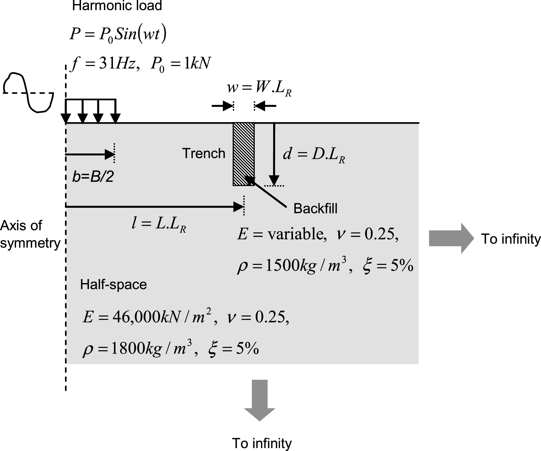
Fig.2
A typical finite element model.
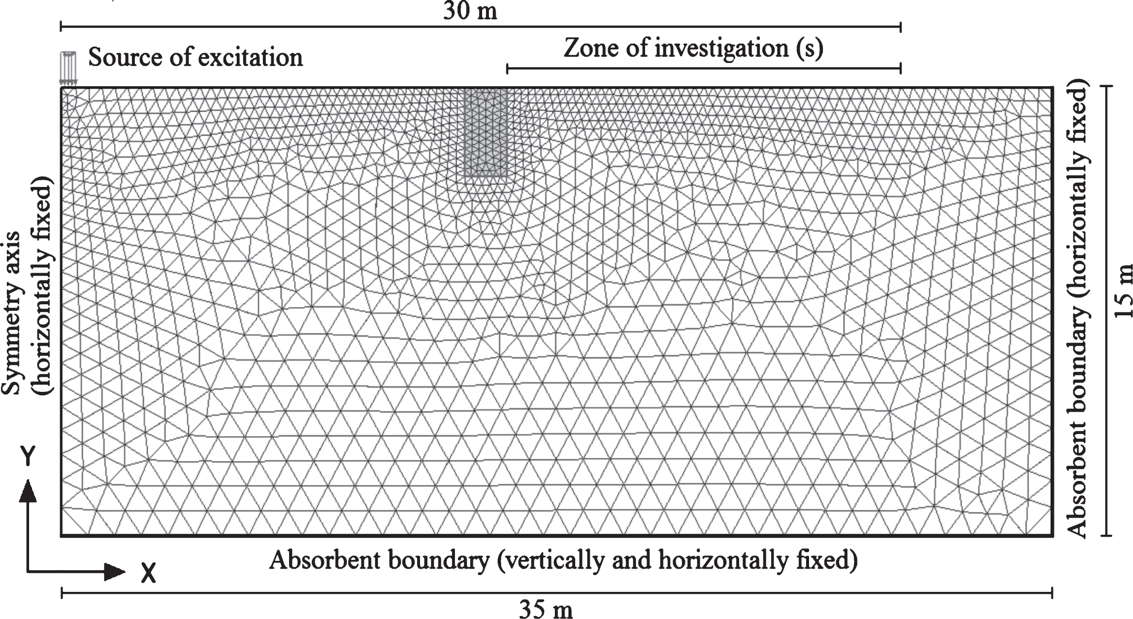
Fig.3
Effect of shear wave velocity ratio of backfill.
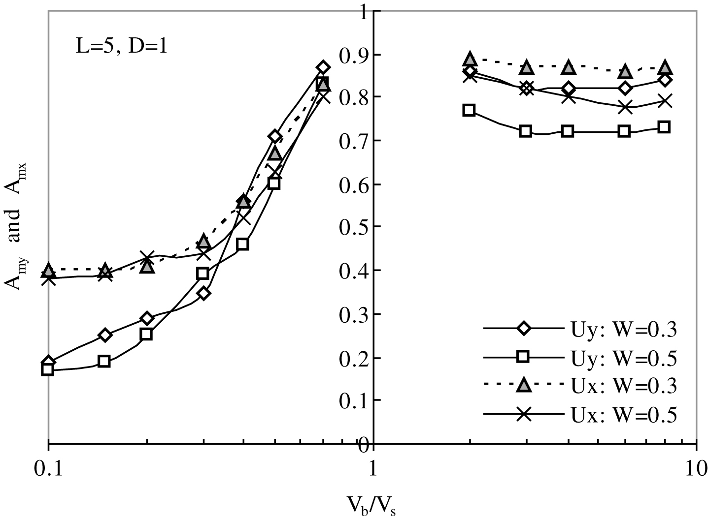
Fig.4
Effect of barrier location (a) W = 0.3 (b) W = 0.5.
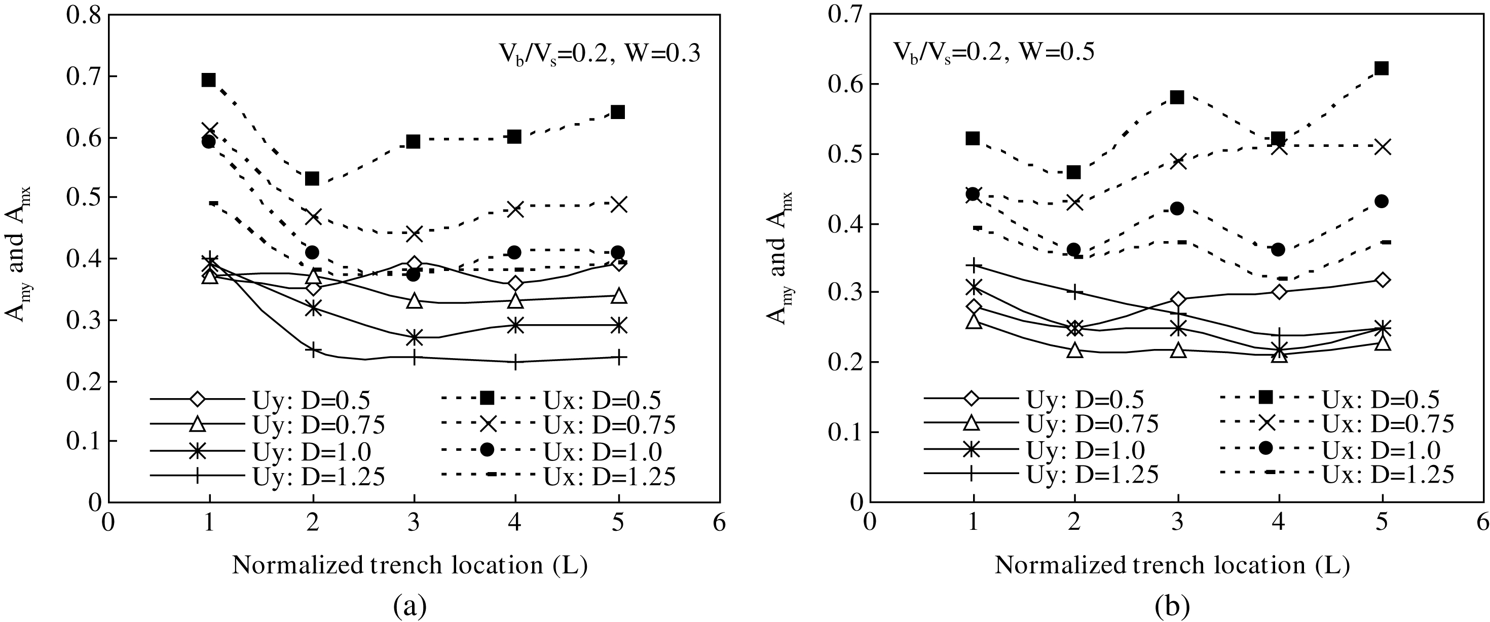
Fig.5
Effect of depth and width on reducing vertical vibration in (a) active case (b) passive case.
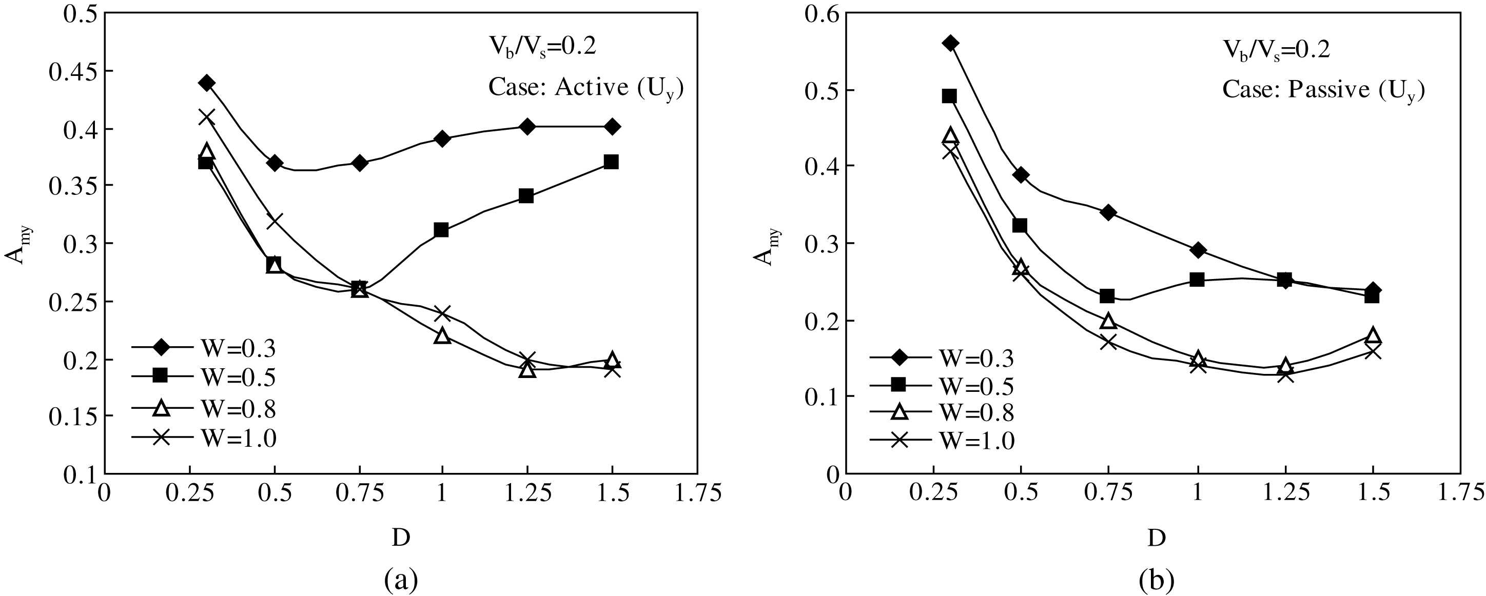
Fig.6
Effect of depth and width on reducing horizontal vibration in (a) active case (b) passive case.
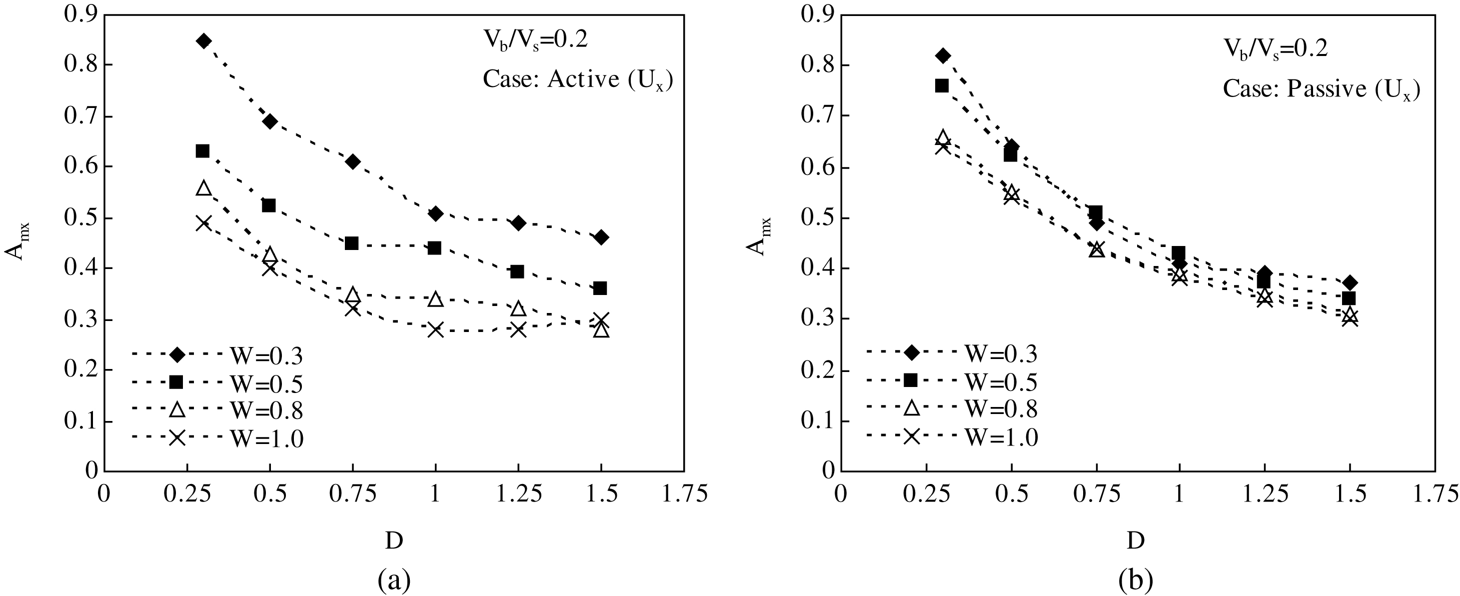
Fig.7
Effect of D/W on reducing vertical vibration in (a) active case (b) passive case.
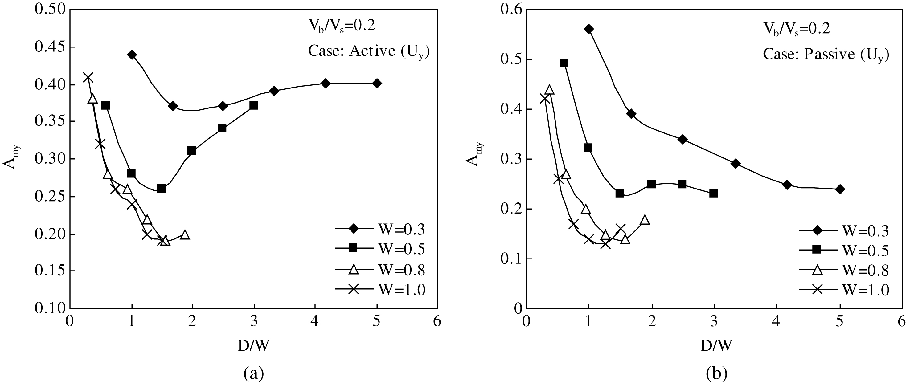
Fig.8
Design charts in active case showing variations of Amy and Amx with Vb/Vs and W (D = 0.5, 0.75, 1.0, 1.25, and 1.5).
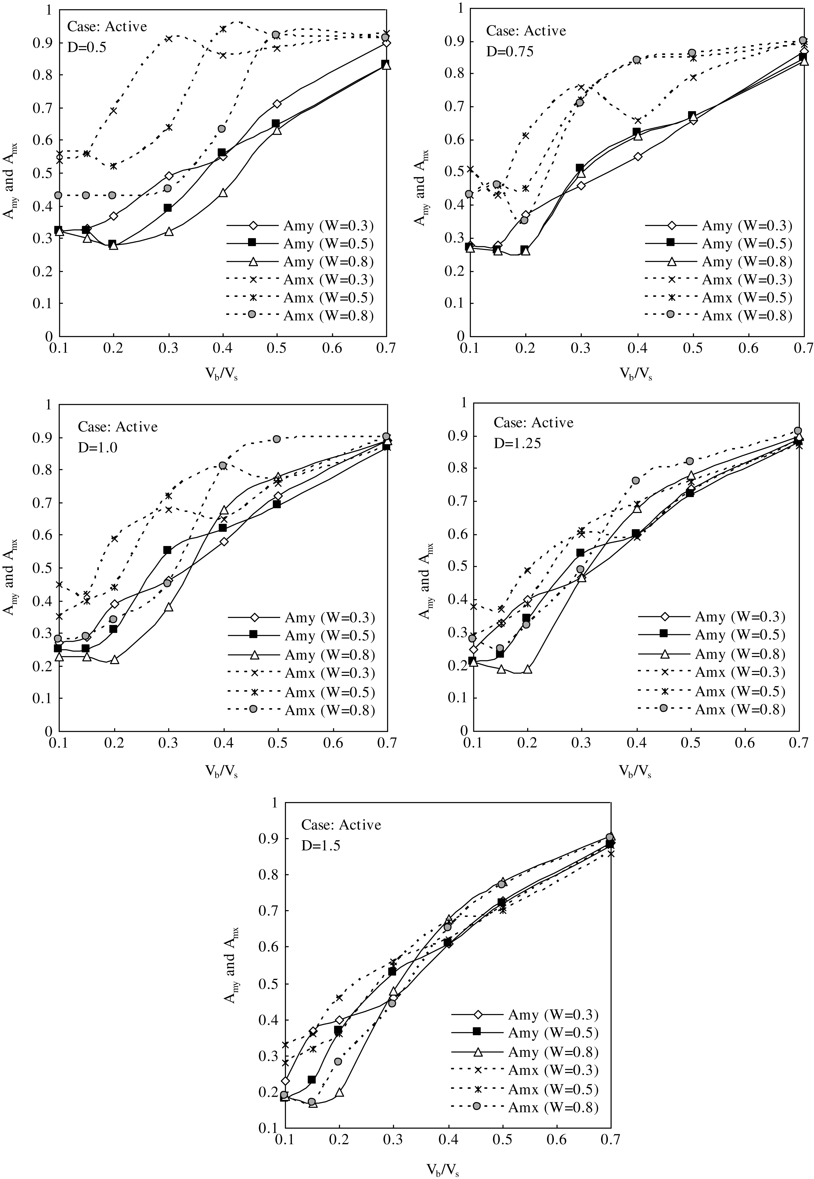
Fig.9
Design charts in passive case showing variations of Amy and Amx with Vb/Vs and W (D = 0.5, 0.75, 1.0, 1.25, and 1.5).
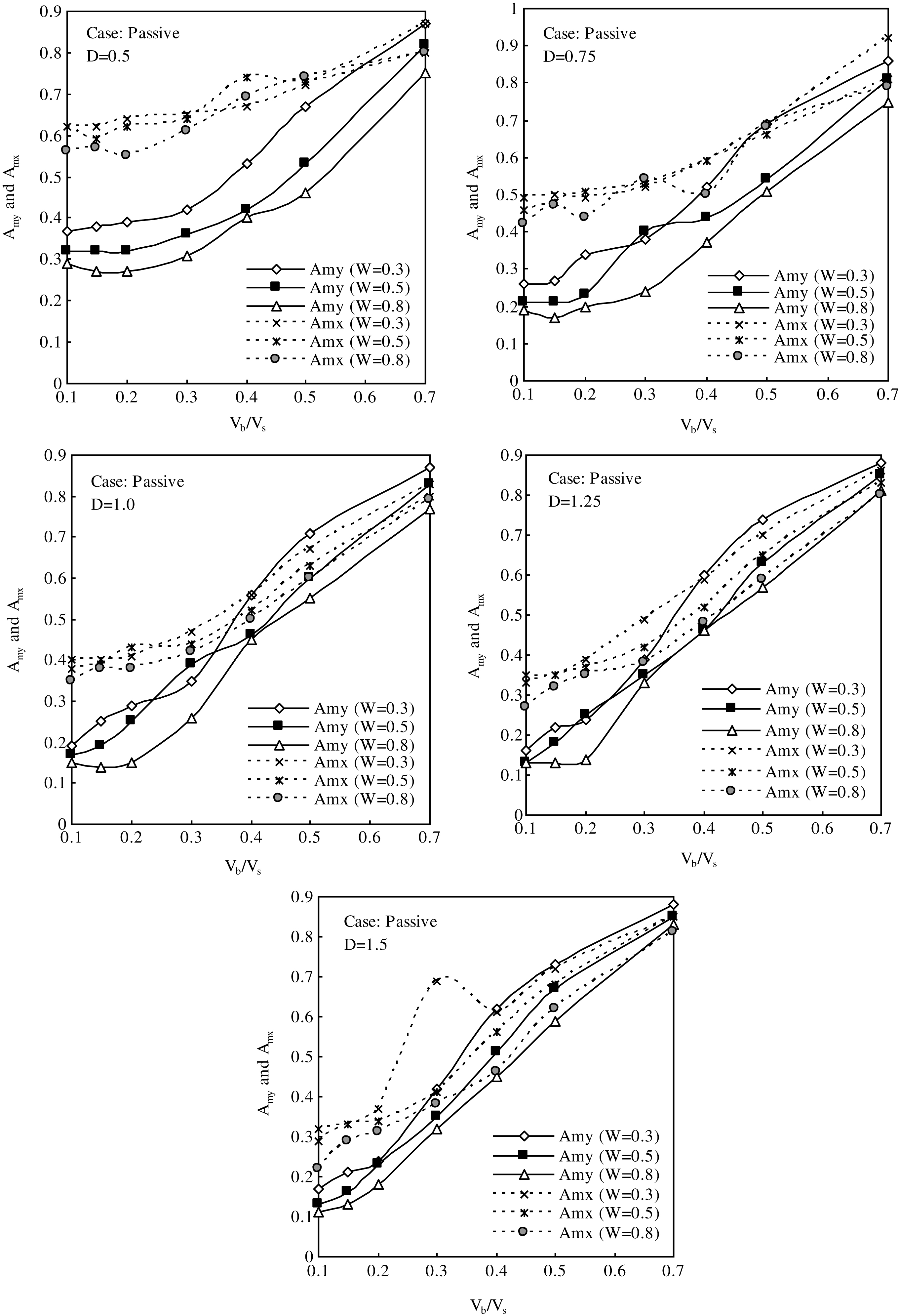
Table 1
Values of parameters adopted in design charts
| Parameters | Adopted values |
| D | 0.5, 0.75, 1.0, 1.25, and 1.5 |
| W | 0.3, 0.5, and 0.8 |
| L | 1 (active case) and 5 (passive case) |
| Vb/Vs | 0.1, 0.15, 0.2, 0.3, 0.4, 0.5, and 0.7 |


