
MobiNET 3D: 3D live virtual robots on mobile devices over the Internet
Abstract
In this paper, we present MobiNET 3D: an m-service application that allows users to view real-time 3D images of a remote robot collaborator on their handheld device. The handheld device user initiates a 3D live session with a remote collaborator. Fifteen cameras are placed around the remote user, and a Virtual View Generating (VVG) server generates a 3D image of the remote collaborator taking into account the viewing perspective of the user. This image is then sent back to the user’s handheld device where it is finally displayed. The goal is to enable the mobile users to have a realistic face-to-face type communication with a remote robot or person.
1.Introduction
1.1.Background
The invention of the telephone by Graham Bell ushered in the first wave of the communication revolution. The telephone had a great impact on the way we used to conduct our lives. People in far away locations could now talk to each other while sitting in the luxury of their homes or offices. As lifestyles evolved and grew increasingly fast, people felt a need to stay connected while being on the move. This was made possible by the development of mobile phone technology.
The growing use of mobile phones and devices and spread of wireless service are making it possible to enable communication with anyone, anywhere and anytime. In many ways cell phones are just smaller, portable versions of a hundred year old invention. Although the current mobile phones support only voice and data (emails, online chatting) services, the next generation phones will allow users to have video conferencing technology. However the new form factor creates both opportunities and challenges. Video conferencing on a handheld device with small screen and limited input may be a less than satisfying experience.
The keen interest in video communication technology is a reflection of the need for inter-personal face-to-face communication among humans. Studies estimate that, depending on their job type, most office workers spend 35% to 75% of their work time in inter-personal face-to-face communication Kraut et al. (1990); Whittaker et al. (1994). When choosing a communication technology for their critical planning tasks, people choose face-to-face communication over other technologies such as email or phone. But face-to-face communication incorporates voice as well as other visual information such as gestures and posture. This information is not captured by the traditional 2D video communication techniques. This led to interest in 3D video technologies that could enhance the effectiveness of traditional videoconferencing techniques Kato et al. (2001).
However, till the recent past, not much effort has gone into studying the use of 3D technology for mobile devices. Our work focuses on providing the effect of a face-to-face communication for handheld device users through the use of 3D live video technology. Users will be able to see and interact with a realistic 3D image of the remote person in real-time. This gives the user a feeling of being in physical proximity with the remote person. Thus his psychological need to be near his friend is satisfied. Co-workers who are geographically separated but require close interaction with each other can now communicate more effectively, thereby improving productivity.
1.2.Related work
The NetICE Leung and Panichpapiboon (2000) system provides an immersive environment to allow people to communicate from anywhere at anytime. Multiple users are seated at their smart terminals and can be connected to the same virtual space. The smart terminals use 3D avatars and audio-visual communication to provide an immersive environment. However, the NetICE system restricts the mobility of the users by requiring them to be near their smart terminals, which are not portable. Moreover, the users can meet each other only in a virtual environment. Thus the real-world information is lost.
Eyematic Inc has developed animated 3D avatars for mobile devices. A user can select a particular animated character to represent him. A face-tracking software analyses the movements of the user’s face, extracts the relevant information and then sends the information to the remote user. The remote participant’s mobile device pre-stores all the animated characters. On receiving information about the animated character being used and the instructions for reconstructing the emotion, it displays them. The advantage of this technique is that it is not bandwidth intensive, since no actual video images are transferred. However, only facial information can be transmitted to the remote user. Another drawback is that 3D avatars are used and the actual image of the user is not transmitted.
Our work differs from the previous ones by providing full body 3D images over portable handheld devices. These 3D images are generated in real-time and are not avatars and so the information of the real world is preserved. The mobile user is free to walk around and view the remote user from any perspective he wishes. Thus he gets the feeling of a face-to-face meeting.
The rest of this paper is organized as follows. An overview of the Mobinet 3D system is given in Section 2. Section 3 describes the 3D image generation mechanism. Section 4 describes the results. We provide a conclusion in Section 5.
2.Mobinet 3D system overview
The Mobinet 3D system of three key components:
1. User’s mobile device
2. Virtual View Generating (VVG) server.
3. Capture hardware and software for capturing the images of the remote user
The VVG server can be located in the same LAN as the mobile user or it can be anywhere in the internet. It handles two tasks –
1. Receiving viewing perspective information from the user, and transmission of the generated video image back to the user
2. Generation of the 3D image.
The overall process can be broken down into five steps. They are illustrated in Fig. 1.
Fig. 1.
System operation overview.
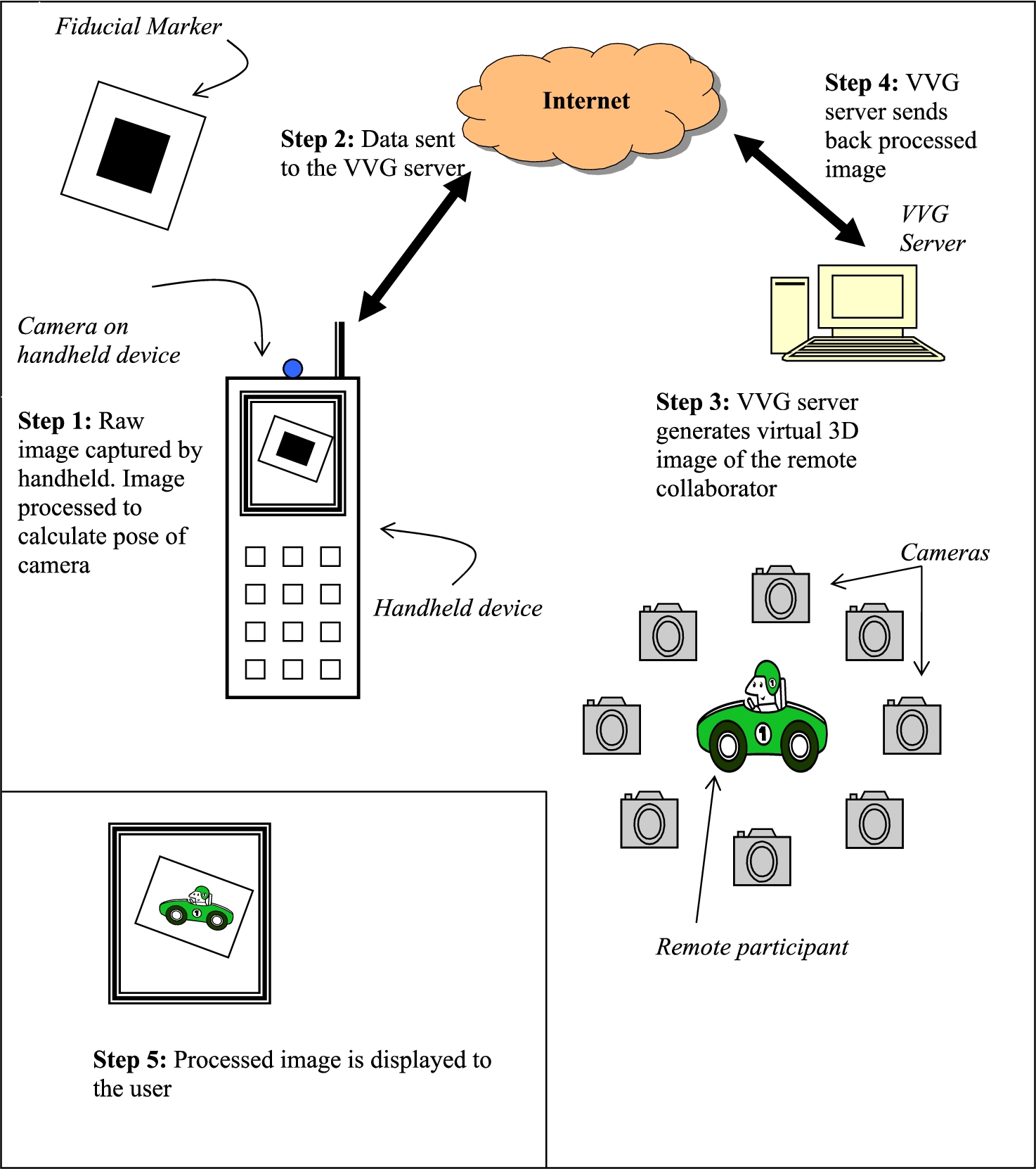
Step 1: User’s handheld generates information about the user’s viewing perspective.
Step 2: Handheld transmits this information over the internet to the VVG server.
Step 3: VVG server generates the 3D image of the remote viewer from the perspective of the user.
Step 4: VVG server transmits the generated image to the user.
Step 5: Handheld displays the received image.
2.1.Technical specifications
We now give the technical specifications for the various hardware and software used in MobiNET 3D.
2.1.1.Handheld device
We used the Sony GT3 as the mobile handheld device on which to run our application. The GT3 uses Transmeta’s 600 MHz Crusoe chip. It was equipped with 8 MB VRAM and 128 MB RAM. For the WLAN connection, we used a Cisco Aironet WLAN card. The WLAN was an IEEE 802.11b network.
2.1.2.Capture hardware and pre-processing software
The capture hardware and software is a commercial system manufactured by Zaxel. Fourteen Sony DCX-390 video cameras were equally spaced around the subject, and one viewed him/her from above. Five 1 GHz video-capture machines received data from three cameras each. The video-capture machines pre-processed the video frames and passed them to the rendering (VVG) server via gigabit Ethernet links.
2.1.3.VVG server
The VVG server was based on dual 1.7 GHz Pentium IV Xeon processors. On the VVG server, the Zaxel software implements a real-time novel view generation algorithm, based on shape-from-silhouette information. When told which viewpoint the remote person should be seen from, the software generates a synthetic view from that viewpoint, using pixels from the live video streams. The software can run at 30 frames per second and returns an image of up to 640 × 480 pixel resolution.
3.Generation of the 3D image
3.1.Tracking the pose of the camera
In order to generate a realistic 3D image, it is essential to know the pose of the camera. A two-dimensional fiducial marker is used to generate this information. As the user moves the handheld around the marker, the pose of the camera is recalculated.
There are two options at this stage. The first is to let the handheld device do the processing of the raw image and calculate the data set which can then be transmitted across to the VVG server. The advantage is that we will have far less data to transmit over the internet, since we are not sending any video images. On the other hand, calculation of the transformation matrix is not a trivial task, and handheld device with a slow processing speed may not be able to do it in satisfactory time. The second option is to transmit the raw image of the marker without processing it. This method does not burden the handheld with the non-trivial task of calculating the transformation matrix. But then we have to contend with longer upload times of the raw video image.
We chose the first option, i.e. we processed the raw image on our handheld. However this technique cannot be employed for devices equipped with slower processors.
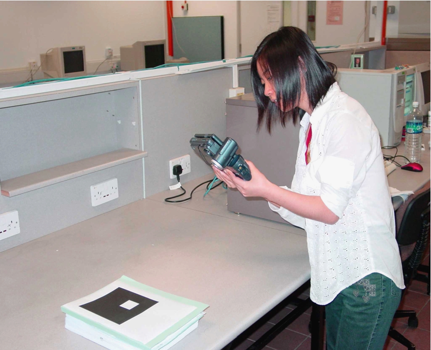
For each frame captured by the camera, the Euclidean transformation relating the marker and camera co-ordinates needs to be estimated. We employ the tracking scheme of Kato and Billinghurst Kato and Billinghurst (1999), which associates the virtual content with a two dimensional fiducial marker. These tangible card markers have the advantage that the virtual captured content can be directly manipulated to achieve the desired viewpoint. Software for this procedure can be downloaded from . Note that the novelty of this paper is not dependent on the tracking algorithm. Any similar tracking algorithm could be used. The novelty of our work is in the generation of the 3D image according to the viewpoint of the mobile user and displaying it on his mobile device. Figures 2 and 3 show a user viewing the marker and moving around it to get a different perspective of the remote collaborator.
Fig. 2.
User viewing the remote object on her handheld device. The camera captures the image of the marker.
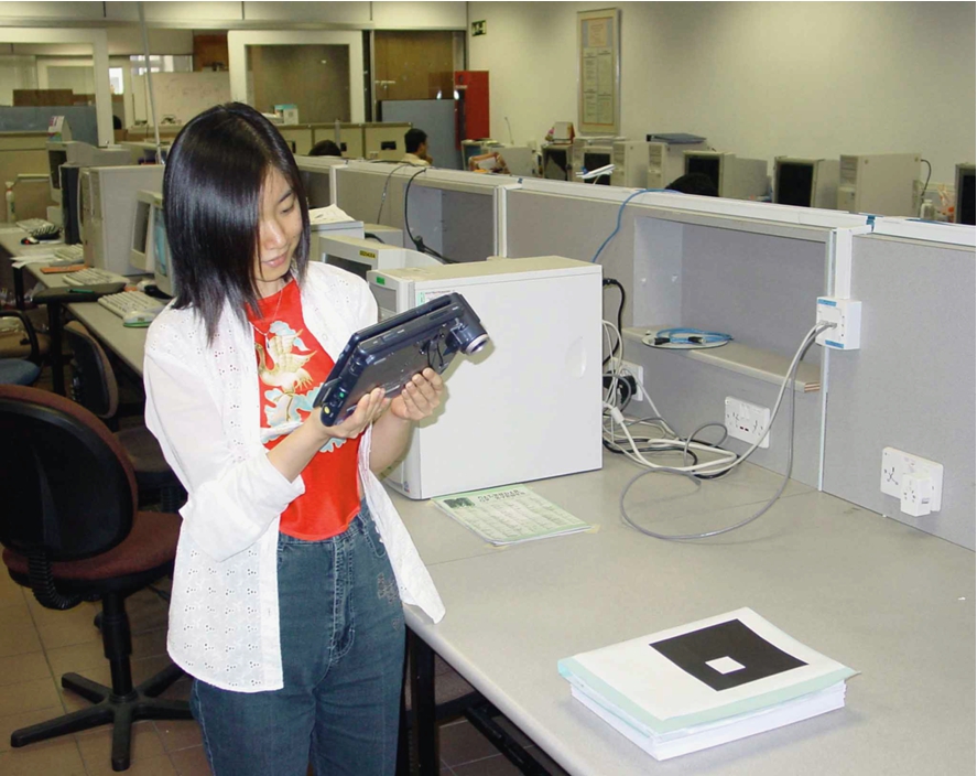
Fig. 3.
User has changed her perspective by moving around to her right.
3.2.Generating the 3D image
This section deals with the actual generation of the 3D image. We use multiple video cameras to capture the remote participant and then generate a virtual image of that remote participant from the viewpoint of the user. This is illustrated in the Figs 4 and 5. We will now describe a fast novel view generation algorithm based on silhouette information from a set of fifteen fixed cameras.
Fig. 4.
User’s view can be different from the position of the fixed cameras.
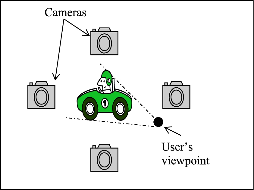
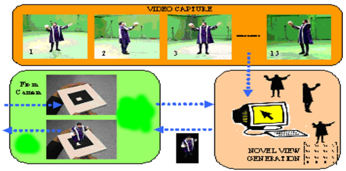
Fig. 5.
The pose of the camera is estimated (bottom left), and the equivalent view of the subject is generated (bottom right) from the incoming video streams (top). This is then rendered into the image (bottom left) and displayed in the user’s hand held device.
3.2.1.Novel view generation algorithm
Our algorithm proceeds entirely on a per-pixel basis. We denote the desired image, the “virtual camera image” and its constituent pixels “virtual pixels”. The virtual camera position is completely described by the product of the (handheld device user’s) camera calibration matrix and the estimated transformation matrix. Given this 4 × 4 camera matrix, the center of each pixel of the virtual image is associated with a ray in space that starts at the camera center and extends outward. A given distance along this ray corresponds to a point in 3D space. We calculate an image based depth representation by seeking the closest point along this ray that intersects the visual hull. This point is then projected back into each of the real cameras to obtain samples of the color at that location. These samples are then combined to produce the final virtual pixel color. The whole algorithm can be summarized in pseudo code as:
3.2.2.Depth search
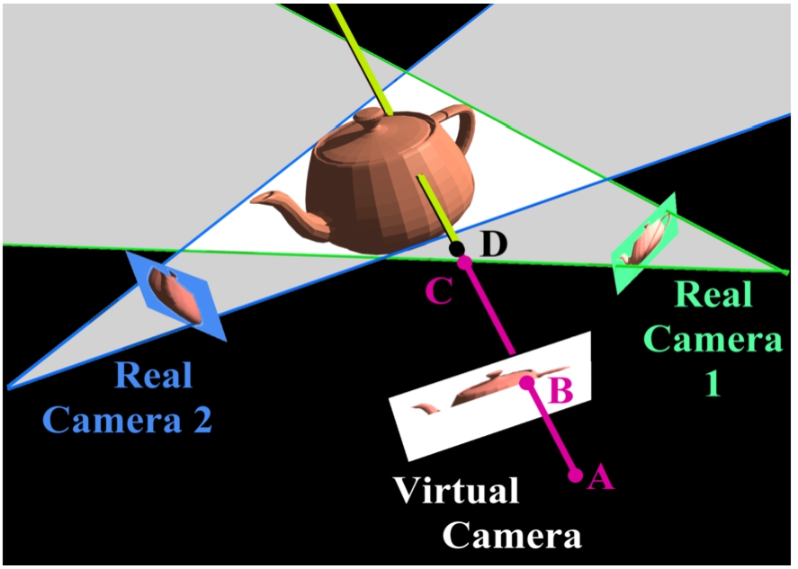
The depth of each virtual pixel is determined by an explicit search starting at the virtual camera projection center and proceeding outward along the ray corresponding to the pixel center. Each candidate 3D point along this ray is evaluated for potential occupancy. A candidate point is unoccupied if its projection into any of the silhouettes is marked as background. This is equivalent to making the assumption that the subject is viewed in every image. When a point is found for which all of the silhouettes are marked as foreground, the point is considered occupied, and the search stops. An example of this search is given in Fig. 6. The search proceeds from the camera center (A) through the pixel center (B). Points C and D cannot be inside the visual hull as they do not project to foreground pixels in both of the real cameras. The search persists until the first point meeting this criteria is established.
To increase search speed the corresponding ray is intersected with the boundaries of each image. The ray is projected into each real image to form an epipolar line. The points where these epipolar lines meet the image boundaries are found and these boundary points are projected back onto the ray. The intersections of these regions on the ray define a reduced search space. This is equivalent to making the assumption that the subject is completely visible in all of the cameras. If the search reaches the furthest limit of the search space without finding an occupied point, the virtual pixel is marked as background. The speed may be further increased by pre-calculating bounding box information for each silhouette and using the intersection of the epipolar lines with the bounding boxes to further diminish the search space.
Fig. 6.
The shape-from-silhouette algorithm divides each image into foreground (silhouette) and background. The recovered shape is the intersection of the 3-D volumes defined by each silhouette (light region). The virtual image is constructed by projecting a ray through each pixel and finding the intersection with the object. Pixel color is determined by sampling the image of this 3-D point in nearby real cameras.
3.2.3.Sampling real images
We now know the position of the 3D point where the ray through the current virtual pixel meets the visual hull. We project this point into the real images to get an estimate of the pixel color. Unfortunately, there are two complications to this process. First, the visual hull is only an approximation of the true shape. Hence, the estimated pixel position in the real images may be inaccurate. There is no simple solution to this problem, other than to minimize the error by basing the color estimate on the cameras which have the visual axis lying closest to that of the virtual camera (see Fig. 7).
The second complication is that the 3D point may be occluded by another object in the real cameras. In order to test whether this is the case, the basic approach is to run the depth search algorithm again on a pixel from the real camera. If the recovered depth lies close enough in space to the 3D point computed for the virtual camera pixel, we assume the real camera pixel is not occluded – the color of this real pixel is allowed to contribute to the color of the virtual pixel. In practice, we increase system speed by immediately accepting points that are geometrically certain not to be occluded (see Matusik et al. (2001)).
Fig. 7.
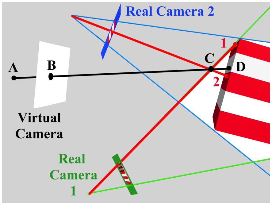
The point on the visual hull (C) does not correspond to a real surface point, so neither sample from the real cameras is appropriate for virtual camera pixel B. In this case, the closer real camera (2) is preferred, since its point of intersection with the object is closer to the correct one.
3.2.4.Calculating pixel color
The simplest method for determining virtual pixel color would be to take the color of the pixel in the nearest un-occluded real image. However, this produces sharp images that often contain visible borders where adjacent pixels were taken from different cameras. Sampled pixel colors vary because of the errors in the depth determination, and non-uniform bi-direction reflectance distribution functions. Hence, we take a weighted sum of the colors from the nearest three cameras where the weight increases as the angle between the axes of the real and virtual camera decreases.
4.Experimental results
Our algorithm allows us to generate the 3D models at interactive speeds. The bottleneck for the performance was the WLAN connection. We conducted our runs during off-peak hours (Sundays, and late nights) when the load on the WLAN was least, and also during peak hours (Weekdays, lunch time). As we had expected, the performance was better during off peak hours. Users were able to get a feeling of interacting with the remote person.
We make the explicit assumption that each foreground object must be completely visible in all of the camera views. This implies a natural trade-off between the capture volume and the quality of the images. As the cameras move away from the subject, the limited resolution of each must be spread over the desired imaging area. Similarly, the accuracy of the depth estimate decreases as the cameras are moved further from the subject. The models in this paper were generated using a relatively large volume of 3.3 m diameter and 2.5 m height. Depending on the application one might want to image a much smaller area (perhaps just the upper torso) to produce more detailed models suitable for virtual collaboration etc.
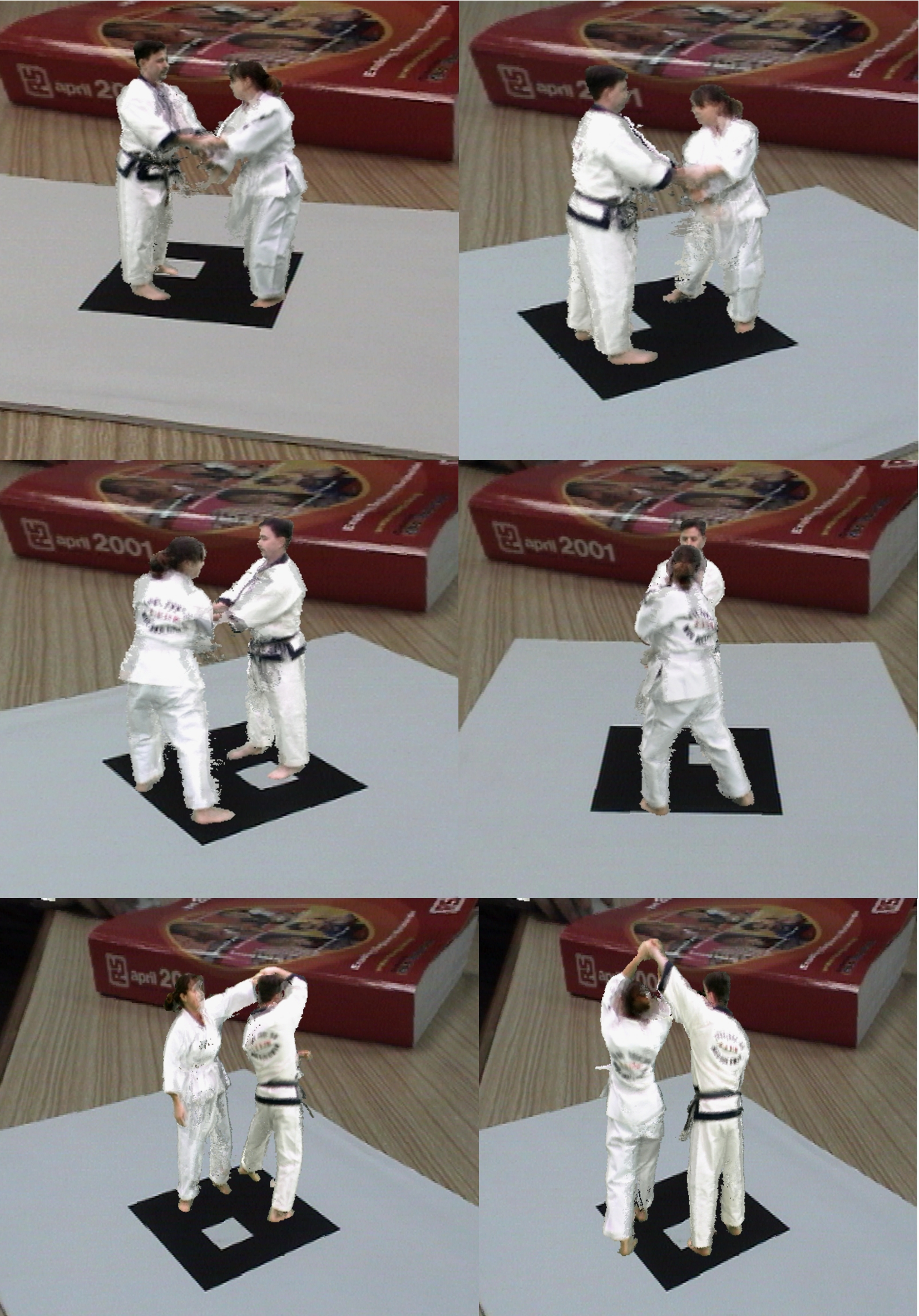
Figure 8 shows the images of a baseball player pitching. Figure 9 shows the screen shots of a user viewing a karate session. The figures in this paper were generated at a resolution of 324 × 288 at 20 frames per sec.
Fig. 8.
The remote baseball pitcher viewed from different perspectives.
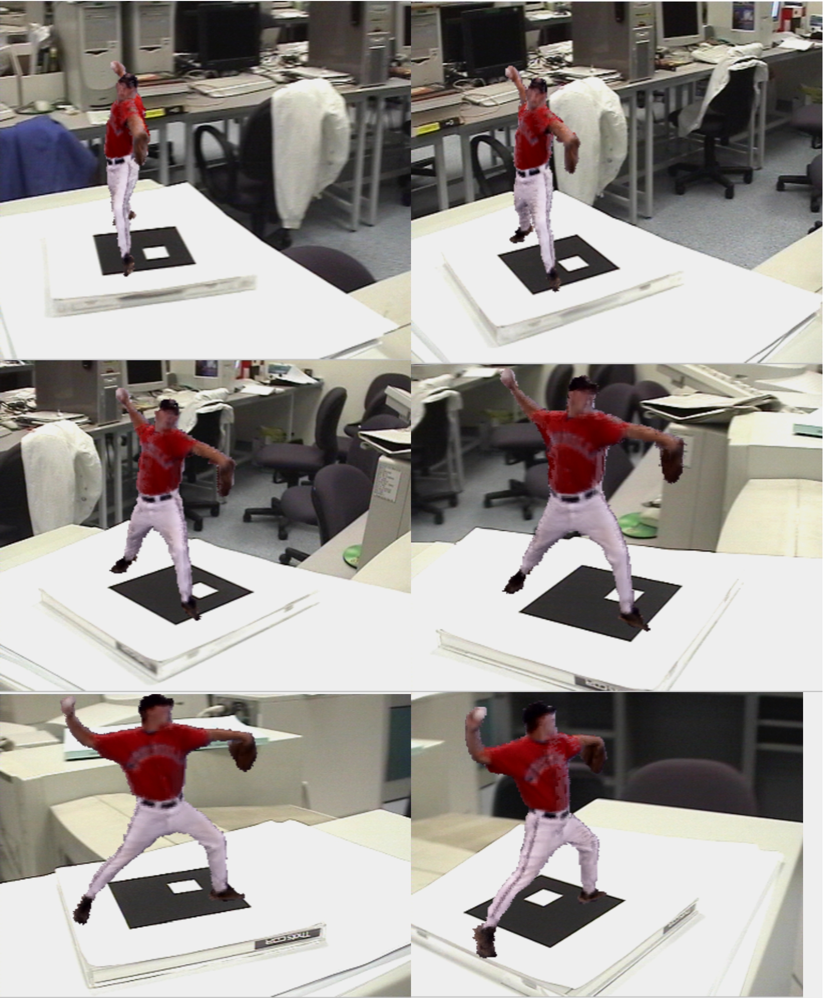
Fig. 9.
Viewing the remote karate session.
5.Conclusion
In this paper we have presented our MobiNET 3D system which allows mobile device users to view 3D images of a remote user in real time. At present, MobiNET 3D has been implemented only for handheld devices having Windows OS. Our future goal is to implement MobiNET on PDAs.
The MobiNET 3D technology can find many useful applications. One example is “3D Salesman”. A salesman can carry a small handheld device with when visiting a customer. On this device he can show life-like 3D images of the product. The user can get to have a look at the product from various angles. This is will provide the user with better information than viewing a plane 2D image.
Another example is“3D Conference Speaker”. Audiences can listen to their own personalized view of the speaker as they move around. At auditoriums with large seating capacity, the audiences at the back can choose to see the speakers on their mobile devices.
The freedom provided by the mobility of the handheld devices combined with live 3D images makes a very powerful combination for providing enhanced communication. We therefore believe that in the future services similar to MobiNET 3D will become common place.
References
1 | |
2 | |
3 | Kato, H. & Billinghurst, M. ((1999) ). Marker tracking and HMD calibration for a video based augmented reality conferencing system. In Proc. IWAR, 1999 (pp. 85–94). |
4 | Kato, H., Billinghurst, M., Morinaga, K. & Tachibana, K. ((2001) ). The effect of spatial cues in augmented reality video conferencing. In Proceedings of the 9th International Conference on Human-Computer Interaction (HCI International 2001), New Orleans, LA, USA, August 5–10, 2001. |
5 | Kraut, R., Fish, R., Root, R. & Chalfonte, B. ((1990) ). Informal communication in organizations. In S. Oskamp and S. Spacapan (Eds.), People’s Reactions to Technology in Factories, Offices and Aerospace, New York: Sage. |
6 | Leung, G. & Panichpapiboon, W.C. ((2000) ). Networked intelligent collaborative environment (NetICE). In IEEE International Conference on Multimedia and Expo, ICME, 2000. |
7 | Matusik, W., Buehler, C. & McMillan, L. ((2001) ). Polyhedral visual hulls for real-time rendering. In Proc. Eurographics (pp. 115–125). |
8 | Whittaker, S., Frohlich, D. & Daly-Jones, O. ((1994) ). Informal workplace communication: What is it like and how might we support it? In Conference Proceedings on Human Factors in Computing Systems: “Celebrating Interdependence”: “Celebrating Interdependence”, Boston, Massachusetts, United States, April 24–28, 1994 (pp. 131–137). |


