
FE-simulations with a simplified model for open-cell porous materials: A Kelvin cell approach
Abstract
In in-silico estimation of mechanical properties of open (Kelvin) cell porous materials, the geometrical model is intractable due to the large number of finite elements generated. Such a limitation impedes the study of reasonable domains. VoXel or Boundary representations of the porous domain result in FEA data sets which do not pass the stage of mesh generation, even for very modest domains. Our method to overcome such limitations partially replaces geometrical minutiae with kinematical constraints imposed on cylindrical bars (i.e. Truss model). Our implemented method uses node position equality constraints augmented with rotation constraints at the joints. Such a method significantly reduces the computational expense of the model, allowing the study of domains of 10
1.Introduction
Porous materials have a wide range of applications that cover different fields such as medicine, biotechnology, automotive industry, design and manufacturing [3, 12, 23]. In many of these applications a mechanical characterization of the material is needed. However, (1) existing material tests are extremely expensive and (2) most of the computer simulations are intractable because of the large size of the models. Therefore, the development of an effective and efficient method for the estimation of the mechanical properties of porous material is a matter of interest.
Different authors have proposed numerical simplified models for the study of the mechanical behavior of porous materials. One of the most common approaches is to represent the complicated geometry of the material with regular arrays of Kelvin cells [9, 13, 14, 4, 11, 10, 15, 23, 17]. Ref. [8] presents another simplification technique (Truss model), in which the ligaments of the material are represented with beams of circular cross-section and variable radius.
In this article we aim to evaluate a variation of the Truss model using Kelvin cells. Our evaluations is purely numerical and neither experimental data nor experimental results are used for benchmarking. The results obtained allow us to confirm that the proposed variation of the Truss model is a promising technique for obtaining efficient and accurate estimations of the mechanical moduli of open-cell porous materials.
This article is structured as follows: in Section 2 we provide a review of the geometric models used for the representation of porous materials. In Section 3 we describe the employed methodology. Section 4 presents and evaluates the results of the simulations. Finally, Section 5 contains the conclusions of this work and possible future improvements on this research.
2.Literature review
Multiple techniques have been used to obtain theoretical and computational models that may be used to study the properties of porous materials, such as: models of regular arrays of polyhedra (Kelvin cells [15, 11, 10, 14, 17, 23, 13, 4] and Weaire-Phelan cells [6]), random tessellation models [16, 21, 13], 3D image-based models [18, 20, 22, 19], and 1D image-based models ([8]). However, given the scope of this research, we will focus on reviewing (1) image-based models (1D, and 3D) and (2) models of regular arrays of Kelvin cells. A description of the other methodologies can be found in [7].
1. Image-based models: These models take a set of images (commonly from a X-ray computed tomography (CT) [18, 20, 22, 19, 8]) of an actual foam sample to obtain an accurate computational representation of the domain of study. The images are processed to retrieve a 3D representation of the foam and to generate its respective FE model [7]. Depending on the type of element used for the FE simulations, these models may be classified as 3D image-based models and 1D image-based models.
(a) 3D or BREP models: The main goal of BREP models is to preserve with a great level of detail the geometry and topology of the original material sample. For this reason, 3D elements (cubic elements from VoXels [22] or tetrahedral elements [18]) are used for the FE meshing. The obtained model consumes significant memory and time in FEA simulations [18, 20, 5]. Therefore, simulations are constrained to small domains.
(b) 1D or Truss models: These models attempt to retain most of the geometry and topology of the original material sample using less computational resources when compared with BREP models [8]. This is achieved by using 1D elements (beams of circular cross-section with variable radius) for approximating foam ligaments. Truss models are used for the estimation of equivalent mechanical moduli (Young, Shear, Poisson) of real foam samples. Errors in the estimations are under 16%, when compared with the respective BREP model. However, BREP model tends to be stiffer than the Truss model.
2. Models of regular arrays of Kelvin cells: This technique has been used to developed both theoretical and numerical models that allow the analysis of the mechanical properties of open-cell porous materials. The studies include the characterization of the compressive [15, 11, 10, 14] and tensile [17] responses, the description and prediction of equivalent mechanical moduli [23, 11, 13], and the analysis of thermal conductivity [4].
In what concerns to the study of the equivalent mechanical moduli of Aluminum foams, authors in [13, 14] report results considering one anisotropic Kelvin cell modeled with (a) 3D solid elements (BREP model) and (b) beams of non-uniform cross section area (Truss model). Errors of the Truss model vs. BREP model are between 14% and 17%, with the BREP model being always stiffer than the Truss model. However, they do not assess the accuracy of the estimations for a domain of more than one cell. They evaluate the results against experimental estimations, which is out of the scope of this article.
2.1Conclusions of the literature review
Based on the literature review, the Truss model excels the BREP model in the efficiency of the use of computational resources. Likewise, the Truss model is able to conserve the geometry and topology of the original foam. However, it is a matter of interest to make the Truss representation stiffer so that it resembles more accurately the behavior of the BREP model.
In this article, we generate a stiffer Truss model by adding rotation constraints at the joins of the bars. We perform an evaluation of the proposed Truss abstraction using Kelvin cells, which is a widely used technique for the analysis of porous materials.
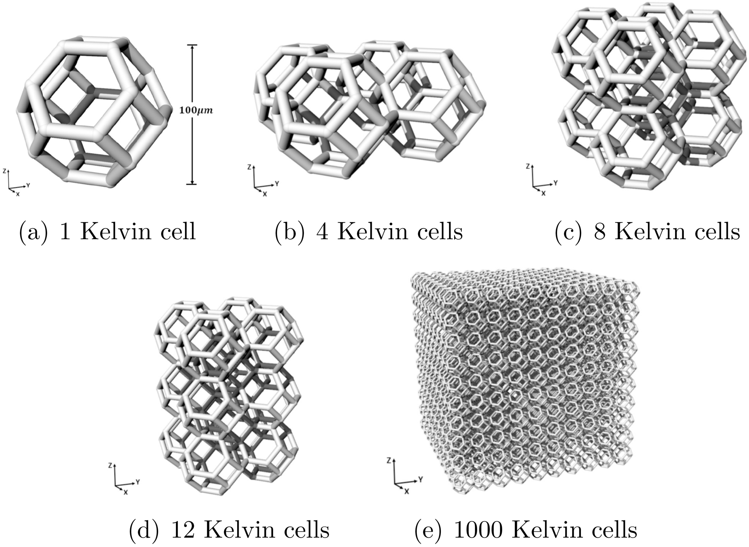
Unlike other approaches in which domains of a single Kelvin cell are considered, we study five domains formed with 1, 4, 8, 12, and 1000 Kelvin cells. The evaluation consists in the estimation of equivalent mechanical moduli (Young’s modulus, Poisson’s ratio) using FE mechanical simulations in compression static tests. We compare the estimations performed by the BREP and Truss modeling approaches for four domains (1, 4, 8, and 12 Kelvin cells). We also show the computational efficiency of the Truss model with respect to the BREP model.
3.Methodology
In order to evaluate our approach to estimate equivalent mechanical moduli of porous materials, we simulate numerical compression tests using ANSYS. Simulations are configured to appraise the models in the elastic region. In addition, to asses the performance of the proposed approach, we compare the estimations of the (a) BREP model, (b) traditional Truss model, and (c) proposed Truss model with restricted rotations, taking the BREP as Reference model to measure the error in the estimations of the other two models.
The addition of rotational constraints at the ligament junctions allows the traditional Truss model to gain torque resistance. Therefore, the traditional Truss model and its variation with restricted rotations may be also called Torque-disabled and Torque-enabled Truss models, respectively.
Figure 1.
Analyzed domains.
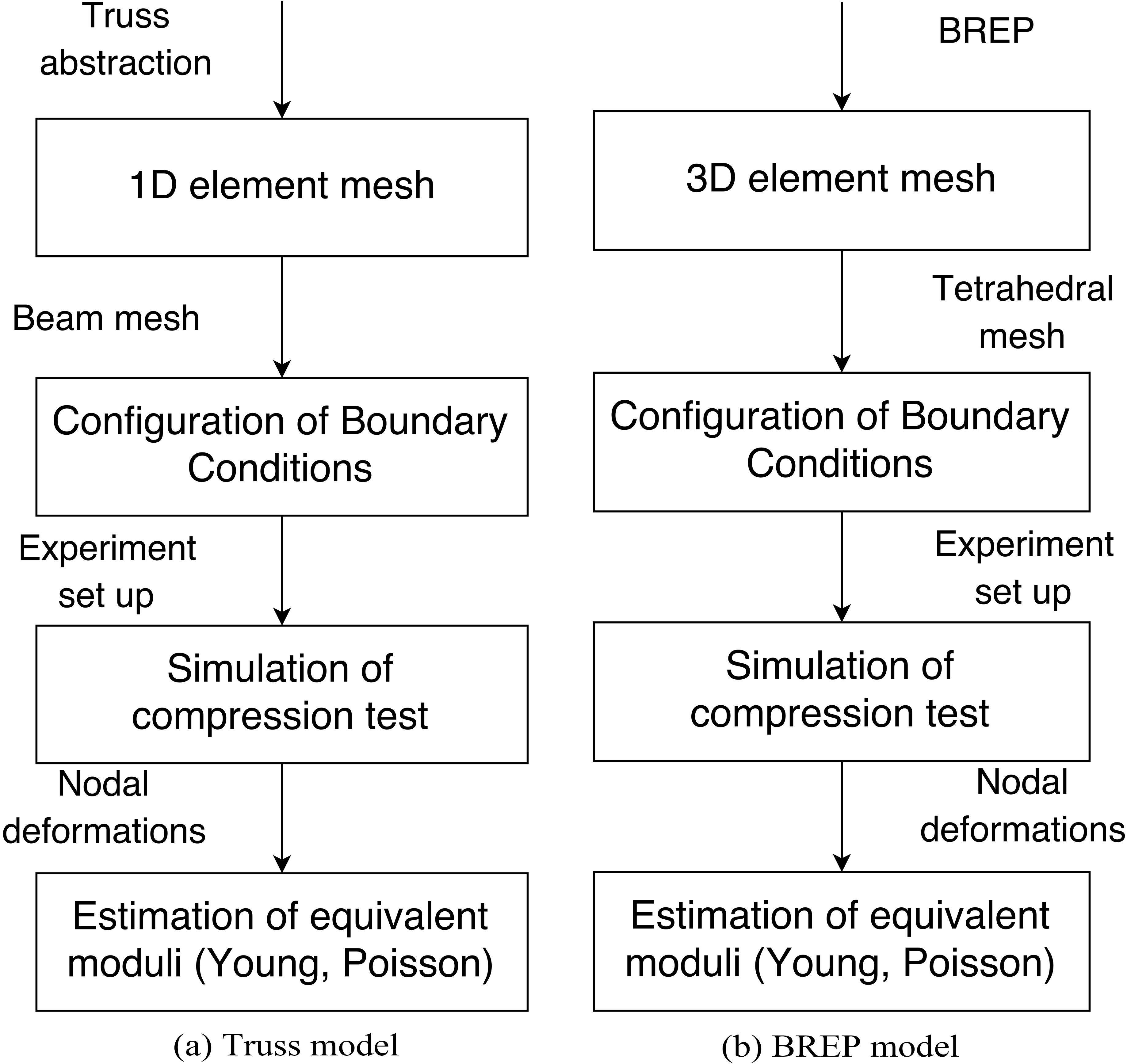
In Fig. 2 we show the process to carry out the mechanical moduli estimations with the BREP and Truss abstractions. This process can be summarized in three main steps:
1. Generation of a suitable BREP and Truss models for FE simulations.
2. Set up and execution of the FE compression test in ANSYS.
3. Estimation of the moduli (Young’s modulus, Poisson’s ratio) based on the resultant nodal deformations.
Figure 2.
Comparison between procedures for the moduli estimation the Truss and BREP models.
3.1Domain characterization
We analyze five domains of isotropic Kelvin cells composed by 1, 4, 8, 12, and 1000 Kelvin cells. Figure 1 illustrates the 5 domains. The specification of the Kelvin cell properties (material and statistical dimensions) corresponds to an existing physical sample with height 100
3.2Generation of BREP and Truss models
3.2.1BREP Model for FEA
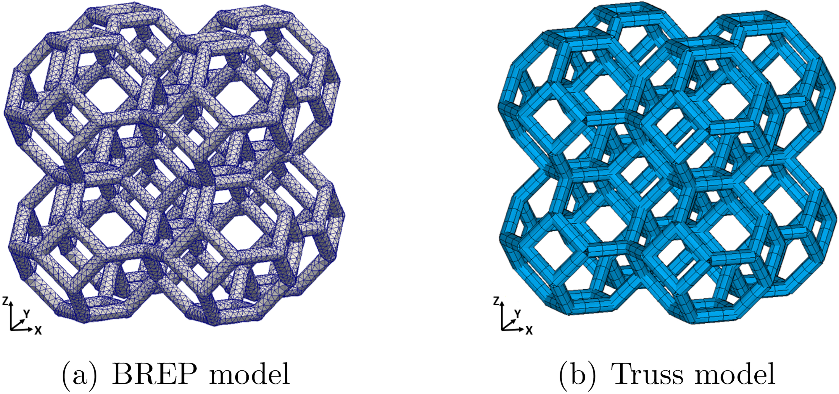
We use Rhinoceros 3D to produce a BREP of each analyzed domain. Then, we generate the corresponding 3D mesh in ANSYS. For full 3D FEA simulation we use elements SOLID185 [1]. These elements are first order ones (2 nodes/edge) and accept linear and non-linear analysis. Other ANSYS elements (SOLID186, SOLID187) have higher order, thus demanding more computational resources. Elements SOLID186 and SOLID187 are not needed for elastic compression loads. Figure 3a presents the 3D mesh generated in ANSYS for the domain of 8 Kelvin cells.
Figure 3.
Meshes generated in ANSYS for the domain of 8 Kelvin cells.
3.2.2Truss model for FEAs
We generate a Truss abstraction of each domain of Kelvin cells using C language. Then, we generate two independent FEA cases in ANSYS that correspond to the Torque-enabled and Torque-disabled Truss models. Figure 3b shows the mesh generated in ANSYS using beam elements. We use BEAM188 for the FE analysis. This is a first order element and serves linear elastic loads (our simulation domain). ANSYS element BEAM189 was not selected since it has higher order (not essential in our case) and thus demands larger computational resources [1].
Table 1
Relative density of the analyzed domains
| Domain | Relative density (%) |
|---|---|
| 1 cell | 6.98% |
| 4 cells | 6.73% |
| 8 cells | 6.56% |
| 12 cells | 6.51% |
| 1000 cells | 6.19% |
3.3Configuration of the compression test
The parameters used for the simulations are reported in Table 2. The set-up of the compression test for the domain of 8 Kelvin cells is displayed in Fig. 4. For the BREP and Truss models, at the bottom of each domain: (1) Z displacement is set to 0, and (2) at least two nodes at the center are embedded (all degrees of freedom are constrained to zero displacement). Compression loads in negative Z direction are applied at the top of each domain. Table 2 shows the magnitude of the loads.
Table 2
Simulation set-up
| Property | Experiment conditions | |
|---|---|---|
| Truss model | BREP model | |
| Material | Al-6101-T6 [13] | Al-6101-T6 [13] |
| Young’s modulus of bulk material | ||
| Poisson’s ratio of bulk material | ||
| Side length of Kelvin cell | 100.0 | 100.0 |
| Ligament radius | ||
| Nodal radius | Does not apply | |
| Total applied stress | 2.50 MPa | 2.0 to 2.3 MPa |
Figure 4.
Domain of 8 Kelvin cells. Boundary conditions for the (a) BREP model (left), and (b) Truss model (right).
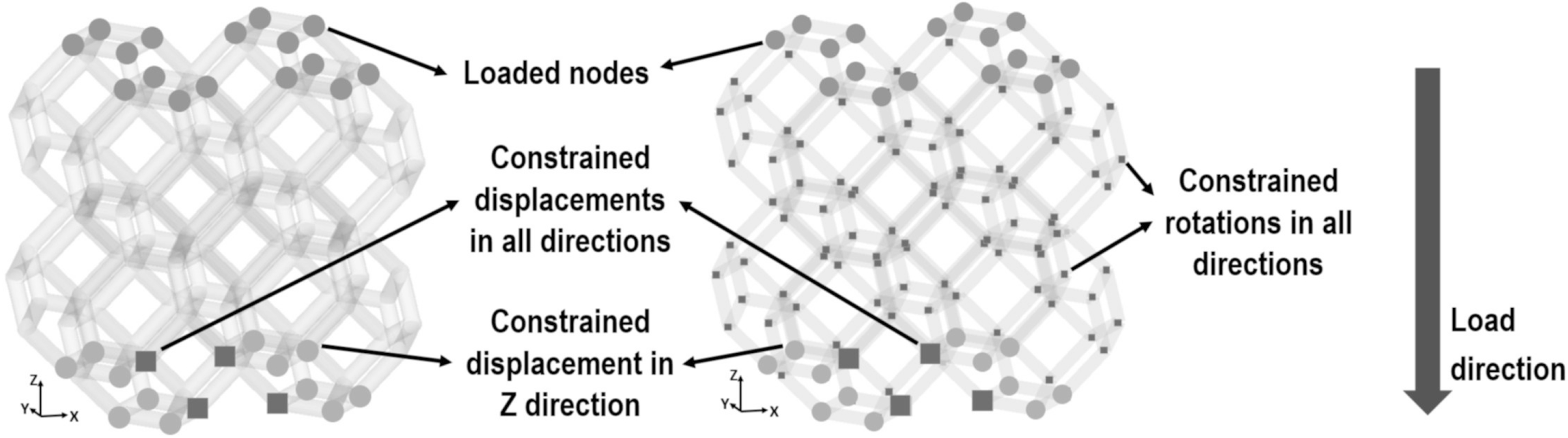
In the case of the Torque-enabled Truss model, at the junction of the ligaments, rotations with respect to X, Y, and Z are set to 0. These rotation constraints allow us to simulate a stiffer Truss model without modeling explicitly the junctions between the struts of the porous domain, which must be modeled when the BREP abstraction is used.
3.4Estimation of Young’s modulus and poisson’s ratio
Young’s modulus
(1)
where
On the other hand, Poisson’s ratio (
(2)
where
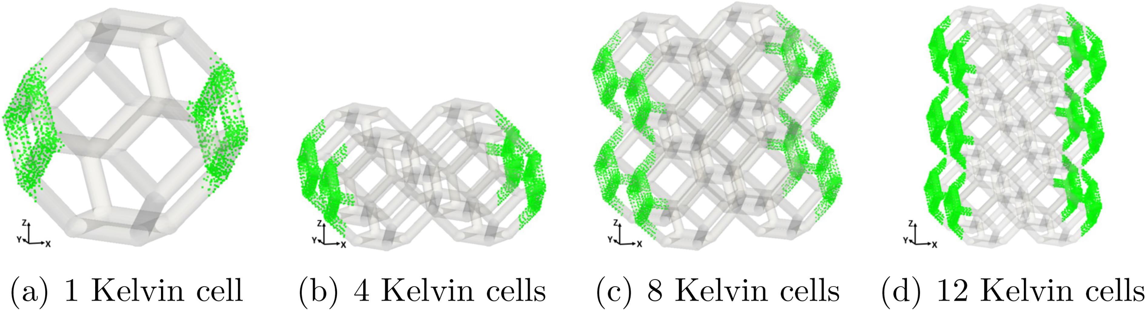
To estimate the strain in each direction, we calculate the average strain for a set of FE nodes in a selected region of the domain. Figures 5 and 6 depict the regions selected for the estimation of X, Y, and Z strain for some of the studied domains. The thickness of each band corresponds to the 10% of the domain size length.
Figure 5.
Selected region to estimate strain in Z direction.
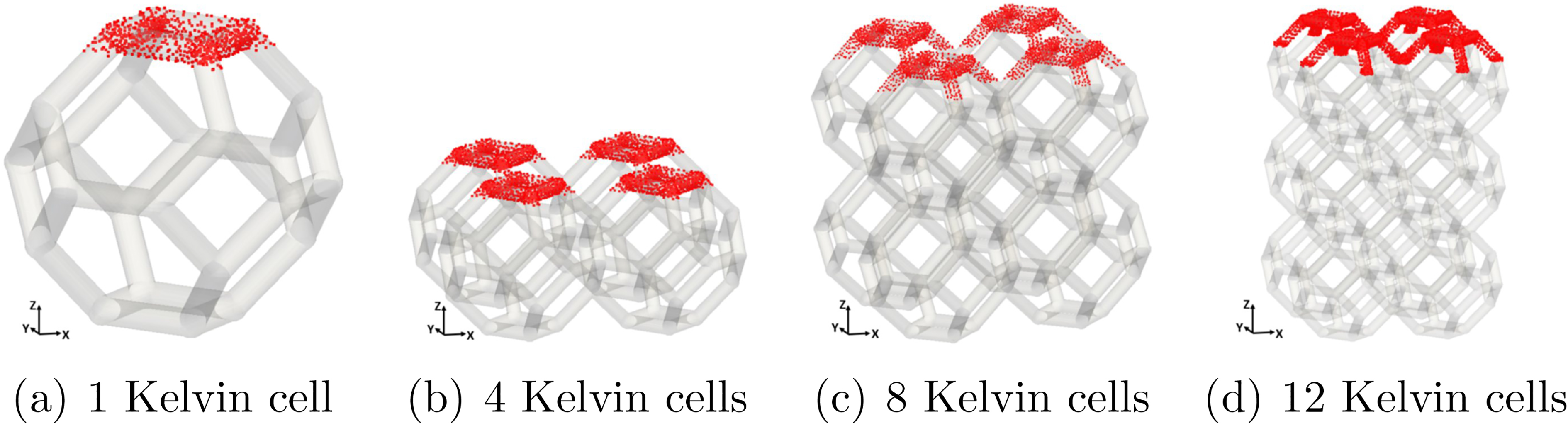
Figure 6.
Selected region to estimate strain in X direction.
4.Results and discussion
4.1Relative density
Table 1 shows the calculation of the relative densities for the five analyzed domains. Notice that for every domain, the relative density is between 6.2% and 7.0%, which lie in the range of typical relative densities for metal foams [2].
4.2Mechanical moduli estimation
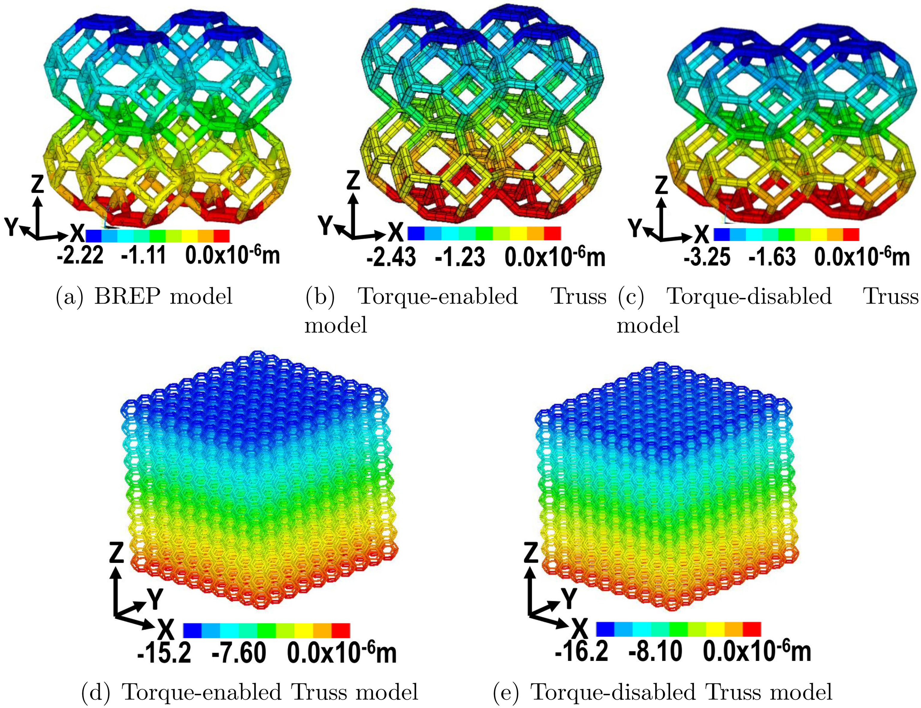
Figure 7 shows the resultant nodal displacements in Z direction after the simulation of a compression test. The figure exhibits the response of the BREP and Truss abstractions for the domains of 8 and 1000 Kelvin cells. The reader may observe that the nodal displacements of each studied domain have the same order of magnitude. Likewise, the nodal displacements for the Torque-enabled Truss model are lower than for the Torque-disabled Truss model.
Figure 7.
Compression test. Nodal displacements in Z direction for the domains of 8 and 1000 cells. Domain deformation is not noticeable in this image.
Based on the nodal deformations, we estimate Young’s modulus (
Table 3
Graphical version in Figs 8 and 9. Mechanical moduli estimation with (a) BREP model, (b) Torque-enabled Truss model, and (c) Torque-disabled Truss model. The BREP model is considered as ground truth. Percentage errors are calculated based on 6 decimal places, while only 2 decimal places appear in this table
| Modu-lus | Domain | BREP model | Torque-enabled Truss model. Relative error % | Torque-disabled Truss model. Relative error % |
|---|---|---|---|---|
| Young ( | 1 cell | 182.07 MPa | 223.96 MPa (23.01%) | 166.57 MPa (8.52%) |
| 4 cells | 200.41 MPa | 230.36 MPa (14.94%) | 149.00 MPa (25.65%) | |
| 8 cells | 223.11 MPa | 208.94 MPa (6.35%) | 162.42 MPa (27.20%) | |
| 12 cells | 234.43 MPa | 202.73 MPa (13.52%) | 165.74 MPa (29.30%) | |
| 1000 cells | NA | 165.72 MPa (NA) | 158.04 MPa (NA) | |
| Poisson ( | 1 cell | 0.49 | 0.45 (8.38%) | 0.47 (3.73%) |
| 4 cells | 0.44 | 0.40 (8.57%) | 0.44 (0.47%) | |
| 8 cells | 0.44 | 0.43 (3.31%) | 0.45 (1.42%) | |
| 12 cells | 0.44 | 0.43 (1.94%) | 0.45 (1.86%) | |
| 1000 cells | NA | 0.45 (NA) | ||
| Poisson ( | 1 cell | 0.48 | 0.45 (6.64%) | 0.47 (1.89%) |
| 4 cells | 0.45 | 0.40 (9.23%) | 0.44 (1.19%) | |
| 8 cells | 0.44 | 0.43 (3.06%) | 0.45 (1.69%) | |
| 12 cells | 0.44 | 0.43 (2.39%) | 0.45 (1.39%) | |
| 1000 cells | NA | 0.45 (NA) | 0.45 (NA) |
For few (less than 8) Kelvin cells, the Truss model does not correctly mimic the BREP model. However, notice that the computational cost of the BREP model is so large that only 12 Kelvin Cells can be modeled in total. It is worth remarking that for larger domains (8 or more cells), the Torque-enabled Truss model almost halves the error of the Torque-disabled model in the estimation of the Young’s modulus, being indeed a stiffer model than the one used in [8].
Figure 8.
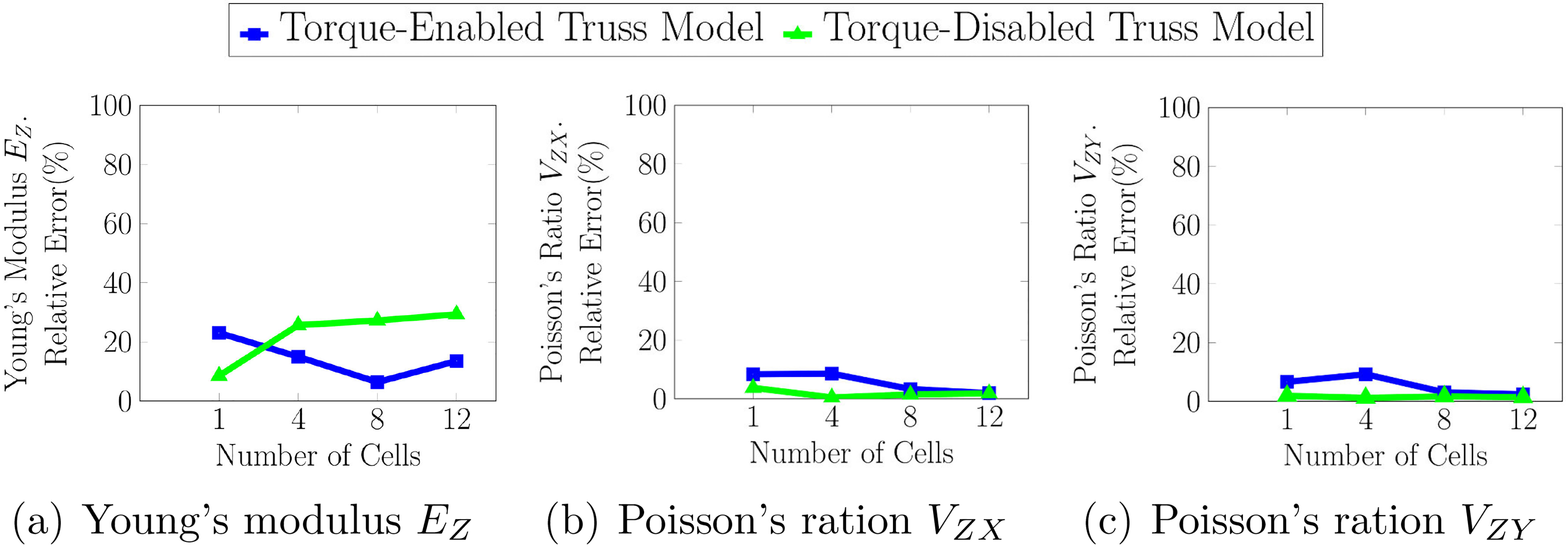
Estimations of the Young’s modulus and Poisson’s ratio using the (a) BREP model, (b) Torque-enabled Truss model and, (c) Torque-disabled Truss model.
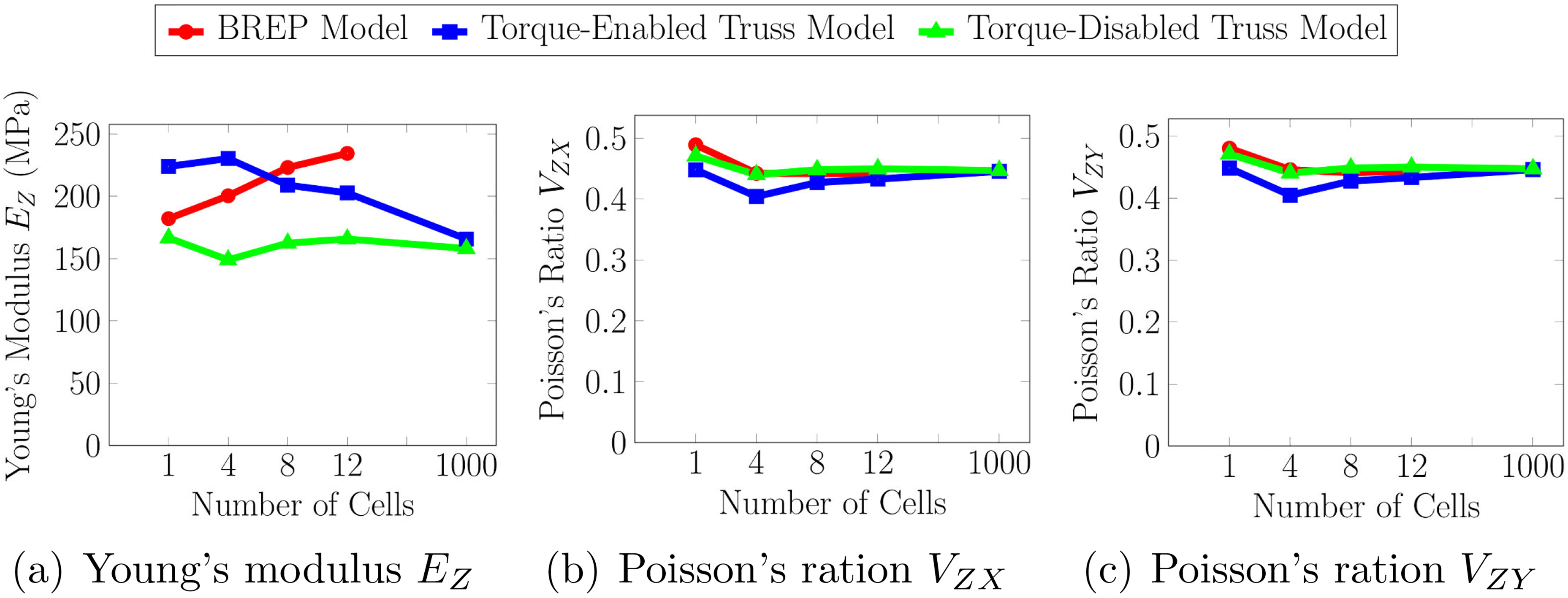
The reader may observe in Fig. 8 that Young’s modulus estimations of the Torque-enabled Truss model tend to decrease when the size of the model increases. Conversely, Young’s modulus estimations of the BREP model tend to increase. This fact may compromise the accuracy of the Truss abstraction for larger domains. However, notice that the estimations of the Torque-enabled Truss model are greater that the ones of the Torque-disabled model, even for the domain of 1000 Kelvin cells. So, for this task, the Torque-enabled Truss model is a better option than the traditional Torque-disabled Truss model.
Errors in the estimations of Poisson’s ratio (
Figure 9.
Relative error in the estimation of the Young’s modulus and Poisson’s ratio for the (a) Torque-enabled Truss model and (b) Torque-disabled Truss model. The BREP model is considered as ground truth.
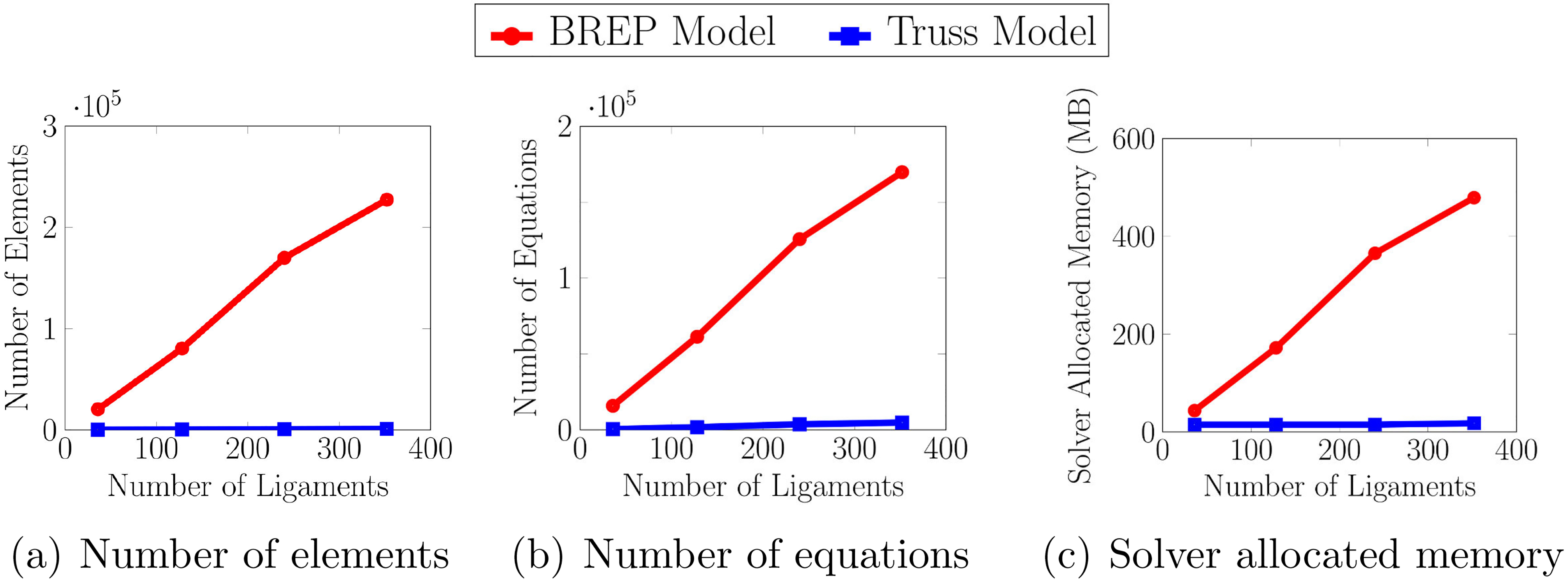
4.3Computational resources
Figure 10 depicts the computational expenses of the BREP and Truss abstractions: (1) the number of elements, (2) the number of equations and (3) the solver allocated memory are presented as functions of the number of ligaments of the studied domains. The computational efficiency of the Truss abstraction is noticeable: the BREP model uses 200 times the number of elements, generates 35 times the number of equations, and spends 20 times the memory of the Truss model.
Figure 10.
Comparison of the computational expenses of the BREP and Truss models.
In order to show that the low computational cost of the Truss abstraction allows the numerical analysis of large domains, we simulate a compression test for a domain composed by 1000 Kelvin cells. The simulation is carried out with the Torque-enabled and Torque-disabled Truss model. Figure 7 shows the resulting nodal displacements in Z direction.
The estimations of the Young’s modulus and Poisson’s ratio are given in Table 3 and Fig 8. A comparison against the BREP model is not feasible, due to the large size of the domain. However, the value of the estimations confirm that the Torque-enabled Truss model remains stiffer than the traditional Truss model even for large domains.
5.Conclusions
In this paper we present a numerical procedure for estimating efficiently macro-mechanical properties of open-cell metal foams with rounded ligaments. We propose and implement a variation of the Truss model that considers torque at the ligament joints of the domain. The performance of this Torque-enabled Truss model is assessed with the estimation of the Young’s modulus and Poisson’s ratio for domains of 1, 4, 8, 12, and 100 Kelvin cells. The results obtained allow us to assert that the Torque-enabled Truss model (1) is an accurate and more efficient alternative for the computational representation of open-cell porous materials with rounded ligaments when compared with the BREP model, (2) is suitable to carry out estimations of the elastic properties of porous materials using numerical simulations, and (3) is stiffer and more accurate than the Torque-disabled Truss model when large domains are considered.
5.1Future work
The Kelvin cell considered in this article is isotropic (i.e., both geometric and lattice manufacturing conditions). On the other hand, in spite of geometrical symmetry, anisotropy may be also introduced by construction orientation (e.g. additive methods). This fact shows that anisotropy in lattice materials is a very extensive and complex research area, which we do not intend to undertake in the present work.
It was observed a trend of the Torque-enabled Truss model to become less stiff when the size of the domain increases. This effect may affect the performance of the proposed approach when compared to the BREP model. Therefore, a further analysis of this phenomenon is left as future work.
Glossary
| BB: | Bounding box. |
| BREP: | Boundary representation of a solid in |
| FE: | Finite element. |
| FEA: | Finite element analysis. |
| Displacement in direction | |
| Displacement of node | |
| Strain in direction | |
| Average strain in direction | |
| Young’s modulus in direction | |
| Coordinate | |
| Length of the domain in direction |
| Relative density of a porous domain (%). | |
| Radius of the ligaments of the domain (m). | |
| Radius of the spheres that model the ligament joints of the domain (m). | |
| Total stress applied in compression test (Pa). | |
| Poisson’s ratio measured from a contraction in direction | |
| (adimensional). | |
| Cardinality of a set. |
References
[1] | ANSYS, Inc, ANSYS Mechanical APDL Element Reference, Release 15.0, (2013) . |
[2] | M.F. Ashby, A.G. Evans, N.A. Fleck, L.J. Gibson, J.W. Hutchinson and H.N. Wadley, Metal Foams: A Design Guide, Butterworth-Heinemann, Burlington, (2000) , pp. 42–44. |
[3] | M.F. Ashby and T. Lu, Metal foams: A survey, Science in China Series B: Chemistry 46: ((2003) ), 521–532. |
[4] | K. Boomsma and D. Poulikakos, On the effective thermal conductivity of a three-dimensionally structured fluid-saturated metal foam, International Journal of Heat and Mass Transfer 44: ((2001) ), 827–836. |
[5] | M. Borovinšek, M. Vesenjak, J. Matela and Z. Ren, Computational reconstruction of scanned aluminum foams for virtual testing, Journal of the Serbian Society for Computational Mechanics 2: ((2008) ), 16–28. |
[6] | B. Buffel, F. Desplentere, K. Bracke and I. Verpoest, Modelling open cell-foams based on the Weaire-Phelan unit cell with a minimal surface energy approach, International Journal of Solids and Structures 51: ((2014) ), 3461–3470. |
[7] | Y. Chen, R. Das and M. Battley, Finite element analysis of the compressive and shear responses of structural foams using computed tomography, Composite Structures 159: ((2017) ), 784–799. |
[8] | C. Cortés, M. Osorno, D. Uribe, H. Steeb, O. Ruiz-Salguero, I. Barandiaran and J. Flórez, Geometry simplification of open-cell porous materials for elastic deformation FEA, Engineering with Computers, ((2018) ). |
[9] | P. De Jaeger, C. T’Joen, H. Huisseune, B. Ameel and M. De Paepe, An experimentally validated and parameterized periodic unit-cell reconstruction of open-cell foams, Journal of Applied Physics 109: ((2011) ), 103519. |
[10] | L. Gong and S. Kyriakides, Compressive response of open cell foams. Part II: Initiation and evolution of crushing, International Journal of Solids and Structures 42: ((2005) ), 1381–1399. |
[11] | L. Gong, S. Kyriakides and W.-Y. Jang, Compressive response of open-cell foams. Part I: Morphology and elastic properties, International Journal of Solids and Structures 42: ((2005) ), 1355–1379. |
[12] | M. Guden, E. Celik, S. Cetiner and A. Aydin, Metals Foams for Biomedical Applications: Processing and Mechanical Properties, in: Biomaterials, Springer US, Boston, (2004) , pp. 257–266. |
[13] | W.-Y. Jang, A.M. Kraynik and S. Kyriakides, On the microstructure of open-cell foams and its effect on elastic properties, International Journal of Solids and Structures 45: ((2008) ), 1845–1875. |
[14] | W.-Y. Jang, S. Kyriakides and A.M. Kraynik, On the compressive strength of open-cell metal foams with Kelvin and random cell structures, International Journal of Solids and Structures 47: ((2010) ), 2872–2883. |
[15] | M. Laroussi, K. Sab and A. Alaoui, Foam mechanics: nonlinear response of an elastic 3D-periodic microstructure, International Journal of Solids and Structures 39: ((2002) ), 3599–3623. |
[16] | C. Lautensack and T. Sych, 3D image analysis of open foams using random tessellations, Image Analysis & Stereology 25: ((2011) ), 87–93. |
[17] | Z. Lu, Q. Liu and X. Chen, Analysis and simulation for tensile behavior of anisotropic open-cell elastic foams, Applied Mathematics and Mechanics 35: ((2014) ), 1437–1446. |
[18] | N. Michailidis, F. Stergioudi, H. Omar and D.N. Tsipas, An image-based reconstruction of the 3D geometry of an Al open-cell foam and FEM modeling of the material response, Mechanics of Materials 42: ((2010) ), 142–147. |
[19] | M.D. Montminy, A.R. Tannenbaum and C.W. Macosko, The 3D structure of real polymer foams, Journal of Colloid and Interface Science 280: ((2004) ), 202–211. |
[20] | K. Natesaiyer, C. Chan, S. Sinha-Ray, D. Song, C.L. Lin, J.D. Miller, E.J. Garboczi and A.M. Forster, X-ray CT imaging and finite element computations of the elastic properties of a rigid organic foam compared to experimental measurements: insights into foam variability, Journal of Materials Science 50: ((2015) ), 4012–4024. |
[21] | J. Randrianalisoa, D. Baillis, C.L. Martin and R. Dendievel, Microstructure effects on thermal conductivity of open-cell foams generated from the Laguerre-Voronoi tessellation method, International Journal of Thermal Sciences 98: ((2015) ), 277–286. |
[22] | E.H. Saenger, D. Uribe, R. Jänicke, O. Ruiz and H. Steeb, Digital material laboratory: Wave propagation effects in open-cell aluminium foams, International Journal of Engineering Science 58: ((2012) ), 115–123. |
[23] | H.X. Zhu, J.F. Knott and N.J. Mills, Analysis of the elastic properties of open-cell foams with tetrakaidecahedral cells, Journal of the Mechanics and Physics of Solids 45: ((1997) ), 319–343. |


