
Motivation as a tool for designing lifelong learning robots
Abstract
Designing robots has usually implied knowing beforehand the tasks to be carried out and in what domains. However, in the case of fully autonomous robots this is not possible. Autonomous robots need to operate in an open-ended manner, that is, deciding on the most interesting goals to achieve in domains that are not known at design time. This obviously poses a challenge from the point of view of designing the robot control structure. In particular, the main question that arises is how to endow the robot with a designer defined purpose and with means to translate that purpose into operational decisions without any knowledge of what situations the robot will find itself in. In this paper, we provide a formalization of motivation from an engineering perspective that allows for the structured design of purposeful robots. This formalization is based on a definition of the concepts of robot needs and drives, which are related through experience to the appropriate goals in specific domains. To illustrate the process, a motivational system to guide the operation of a real robot is constructed using this approach. A series of experiments carried out over it are discussed providing some insights on the design of purposeful motivated operation.
1.Introduction
Traditional robotic control design has usually involved the determination of a series of use cases for the robot through the specification of the domain the robot had to operate in and the tasks it had to perform (goals it had to achieve) in those domains. Everything was known beforehand by the designer, who defined how the task was carried out and the goal to be achieved, and implemented the appropriate control policy [1, 2, 3, 4, 5].
As domains become more complex and the number and sophistication of the sensors and actuation mechanisms of robots grow, it becomes increasingly difficult for the designer to be able to reliably program in the policies that are needed in order to perform the tasks. This is where robot learning and adaptation approaches come in. Most of these approaches, such as supervised learning [6], Reinforcement Learning [7], or others [8, 9], define a domain and a task to be carried and provide algorithmic structures that allow the robot to learn the corresponding policy from a series of samples of interactions of the robot with the domain. This way, policies can be obtained, and the role of the designer is limited to the decision of the domain and the task the robot must perform.
The problem arises when the objective is to design robots for autonomous operation. In this case, the designer does not know beforehand the domains the robot will face nor the goals it will need to achieve in those domains. This is called the open-ended learning problem. The robot is expected to learn an unbounded sequence of a priori unknown tasks in unknown domains [10]. Obviously, under these conditions, domain related goals and rewards cannot be provided by the designer. The robot must figure out what tasks to carry out in each domain, and how. It must find and achieve its own goals, which is a much more difficult problem than the ones presented before.
Thus, the issue is how a designer can go about designing robots that must operate in open-ended learning settings carrying out tasks that are useful to the robots and that serve a purpose to the humans that construct them. A second, but also important question, is how this can be achieved in a way that is efficient from a learning and adaptation point of view.
Thrun and Mitchel [11] postulate that lifelong learning may allow to do better than simply handling each learning process in each domain independently. Under open-ended learning conditions, the robot may benefit from reusing knowledge acquired in different learning processes, making posterior learning challenges progressively more accessible.
Lifelong learning can benefit from the principles and advances of developmental robotics [12] and, in particular, those of cognitive developmental robotics (CDR) [13, 14]. This approach addresses the design of robotic systems based on insights from neuroscience studies on the ontogenetic development of cognition, mostly in children [15, 16]. It deals with the progressive acquisition of abilities which are later used as scaffolding to acquire new, more complex, competences through interaction with the world.
If one wants to implement domain independent design processes, as the domains are not known beforehand, the only available choice is to define purpose in terms of the robot itself. In other words, we contend that the purpose of the robot should be introduced with respect to its internal states, and then a series of procedures defined that allow linking these internal states to what is achievable in each domain.
One possible way to endow a robot with purpose, is for the designer to first establish an internal state space defined by a set of domain independent variables the robot has access to. This space will be called the motivational space. Within this space, the designer may define some areas or points the robot should reach that reflect its needs in terms of meeting some internal criteria. The criteria can be concrete values of sensors, increases in values, or any other, just as long as it is measurable. Hence, needs can be defined as internal states in motivational space the robot seeks to achieve or maintain. The deviation from a criterion, represented as a variable, is called a drive, and its functional form must be defined by the designer.
Once the robot needs and associated drives have been set, it must figure out what tasks to carry out to fulfill them when confronted with an unknown domain. In other words, it must self-discover and self-select goals within the domain that will lead to the fulfillment of its needs.
All these aspects are related to motivation, i.e. what makes a system act to achieve some type of purpose, and motivational structures, i.e. what are the data structures and the operational mechanism that are necessary to implement motivation. These structures have been studied for decades in the psychological and educational literature [17, 18, 19, 20] and, more recently, a profusion of papers have addressed their effects on cognitive structures in the computational literature [21, 22]. However, most of the work has concentrated on studying the effects of different motivational strategies [23, 24], especially those related to intrinsic motivation [24, 25], or how to construct mathematical representations that could be used to support them [26, 27]. Very little work has been devoted to the design and engineering of motivational structures to endow robots with purpose in lifelong open-ended settings.
This paper is an extension of [28], presented at IWINAC 2019, in which we dealt with how to induce learning of basic skills (needed to perform tasks) using cognitive motivations. Here, we try to address and formalize the problem of engineering a complete motivational structure that drives a cognitive architecture. Unlike other approaches, we describe a structured path to the design of robots that can learn to operate in open-ended settings producing behaviors that comply with the purpose the designer has in mind for the robot.
Figure 1.
Deliberative model.
In this line, Section 2 addresses the issue of how motivation can be engineered. It describes the different elements that make up a motivational system and how they are organized. Section 3 studies how drives can be categorized and proposes a basic motivational management structure. A series of experiments with the motivational structure are described in Section 4 with the objective of clarifying how a lifelong learning system can be designed and tested in a real robot setup. Finally, Section 5 presents a series of conclusions and open research lines.
2.Engineering motivation
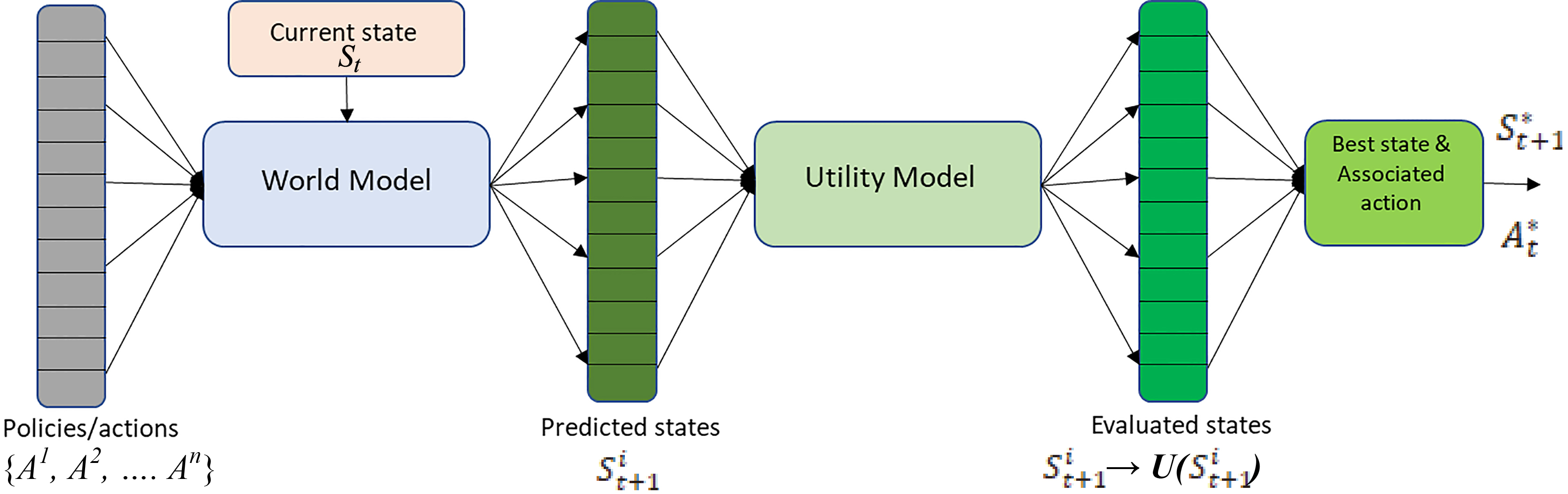
According to Barto [29], motivation consists of a series of “processes that influence the arousal, strength, and direction of behavior”. A robot designed to operate in open-ended learning settings [10] must possess some type of motivational structure in charge of determining what it should strive for in a given domain each moment in time [21]. Motivation provides structure to the evaluation of states, required by decision processes, through the determination of the goals the robot must achieve at each point in time. Once a goal is set, the robot can evaluate different alternative paths of action, estimate their usefulness in achieving that goal, and choose the optimal one.
2.1Needs and drives
Looking at this more formally, and from a deliberative point of view (Fig. 1), given a robot in a state
In the field of reinforcement learning (RL) [7], the functions used for calculating utility are called value functions. Value functions [30, 31] represent the expected utility of each point in state space concerning a goal. That is, the probability of achieving utility starting from that point. In RL it is generally assumed that the robot will operate in a known domain. Consequently, at design time, the robot designer can decide on the goal or goals that must be achieved as points in the robot-domain state space that need to be reached.
State utility and goals, as well as world models, are domain dependent elements. However, in open-ended learning, the domains the robot will operate in are not known at design time. Therefore, they cannot be used by the designer to design purpose. Another approach must be found to define purpose that does not involve knowing domain dependent goals beforehand.
One possible way to produce meaningful oriented behavior in robots is related to the definition of a motivational structure based on needs and drives [32, 33]. Needs are defined as internal states the robot seeks to achieve or maintain. They live in the motivational state space of the robot,
A drive,
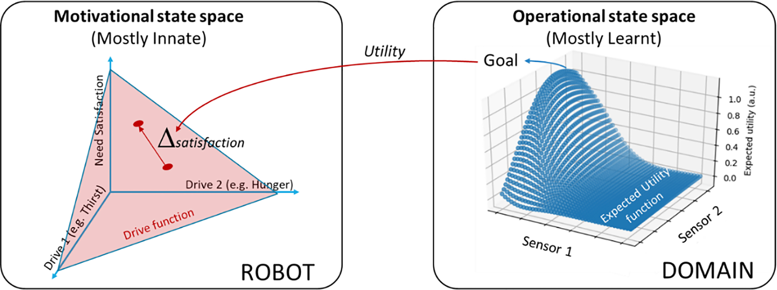
Figure 2.
Diagram showing the relationship between motivational and operational state space. Left: Motivational state space is domain independent and constructed from a series of designer provided drives through drive functions that relate them to the satisfaction of their associated needs. A robot always seeks to satisfy needs. Right: From a robot perspective, each domain implies an Operational state space in which some points (goal points) provide utility, which imply increase in need satisfaction. These goals must be found and to be able to consistently reach them, the robot must generate and store an Expected Utility function leading to each goal.
This function f
2.2Utility and expected utility
From the point of view of this approach to purpose, robots always strive to fulfill their internal needs by reducing the value of their drives. Consequently, they need to find perceptual situations,
It thus follows that a utility model UM could be defined that provides values for the components of the utility vector (each one related to one drive) of each state.
Where
In most real operational state spaces, only a few points or areas actually provide utility. This means that UM is seldom very informative with regards of how the robot must get to those points in state space. That is why many authors resort to modeling state space in terms of expected utility [26, 27]. The expected utility
One prominent feature of
Now we have a tool available to the system designer that allows defining purpose within the robot in a manner that is independent from any domain the robot may find itself in. Each drive reflects how far the system is from satisfying a need the designer has put in because it was deemed important for the robot, regardless of how this need can be satisfied in a specific domain. The satisfaction of these needs is achieved by finding points in the different operational state spaces (those corresponding to the different domain the robot faces) that lead to a reduction in the corresponding drive values. Different domains may lead to different ways of satisfying the same need and, thus, to different goals requiring different skills.
Consequently, in a motivational architecture for open-ended operation, the system designer defines what the robot must do in terms of needs that must be fulfilled and balances the importance of these needs by means of the appropriate definition of the drive functions associated to them. Each drive function may behave differently, that is, one drive function may be linear with respect to the distance to its associated need and another may be quadratic. Figure 2 displays a diagram of the ideas presented in this section.
Even though in this structure the only control over the purpose of a cognitive robot a designer has is by defining needs and creating the appropriate drives, a motivational structure needs more components than these in order to be able to actually lead the robot to some result. Basically, it must have components that allow to efficiently explore for goals, to construct utility models, and to contextually recall previously learnt situations. The last two mechanisms are preset by the cognitive architecture. Hence, they are not controllable by the robot designer when attributing purpose to a robot, but they must be considered for any robot to be able to actually operate in open-ended learning settings.
In this paper, as the objective is to explore how a robot can be attributed domain independent purpose, we will not go into the details of the different mathematical and algorithmic approaches to the modeling of utility. Neither will we go into how the relationships between goals in particular domains and drives can be contextually related in a memory structure. These aspects have been addressed by us and other authors in the literature [27, 35, 36]. Here we will just make use of the corresponding components and concentrate on those aspects the system designer has access to. These aspects allow the designer to give purpose to the robot and induce the efficient exploration of domains.
2.3Operational and cognitive drives
In the previous section, we have described a formalization of the relationship between domain independent needs and drives and domain dependent goals in order to provide a designer with the tools to design in purpose in a robot cognitive structure. A drive related to endowing a robot with purpose is called an operational drive (
Utility is generally very sparse in most operational state-spaces, which display extensive areas that are barren of utility. This affects the definition of needs and drives that the system designer must put in. In fact, to be able to find a point that produces real utility, it is often necessary to first acquire some skills that do not lead to utility producing goals. If the designer wants the robot to explore and acquire those skills, it needs to provide it with motivations (needs and drives) that will allow establishing some type of “virtual goal” that permits performing these learning processes.
In the classical psychological and educational literature on motivation, most authors distinguish between two classes of motivations from an external observer’s point of view. On the one hand, when the agent is perceived as trying “to obtain some separable outcome” [37], it is said to be extrinsically motivated [38]. The observer sees the agent seeking goal states where some observable explicit utility can be obtained. On the other hand, animals and humans spend time and effort carrying out behaviors that produce no observable explicit utility. This has been explained away as driven by intrinsic motivations [20, 39, 40]. Intrinsic motivations are said to drive the autonomous, open-ended acquisition of knowledge and competence in the absence of direct operational goal related feedback [25, 41, 42]. Ryan and Deci’s words this implies: “the doing of an activity for its inherent satisfaction rather than for some separable consequence” [37]. This type of motivations are purported as very important for animals and humans to be able to acquire knowledge such as models or skills that allow them to later on establish strategies to reach goals [21].
When the objective is to engineer motivational systems, intrinsic motivations only differ from extrinsic ones in the fact that their needs and drives are generally related to cognitive aspects of the system rather than operational or maintenance aspects. They are there to induce learning and thus satisfy learning needs. Their satisfaction may be related to how much is explored (e.g. novelty [43]), to obtaining models of the world (e.g. curiosity [44]), or to generating virtual goals by seeking to find ways to produce effects over the environment (e.g. effectance [41]). These cognitive drives (
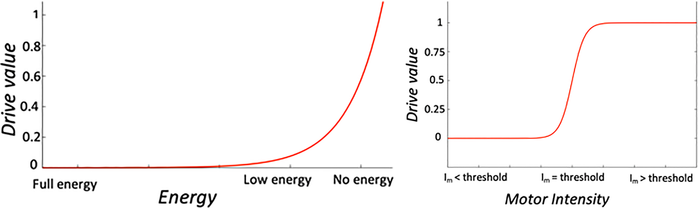
Figure 3.
Examples of drive functions. Left: Energy drive represented with a power function
Summarizing, the purpose of a robot is determined by the operational drives the designer puts in, which will try to exploit the, often sparse, utility landscape of the different domains. However, an adequately designed cognitive drive set results in a denser distribution of utility when interacting with the operational state space. Additionally, the actions chosen by the system to achieve utility in the cognitive state space, induce directed and efficient exploration in the operational state spaces. Thus, cognitive drives indirectly allow the robot to explore its operational environment and learn how it works through the acquisition of models as well as to find operational goals within it.
3.Designing drives
When designing the motivational structure of a robot, the system designer must address the design of two different types of drives: operational drives (
Table 1
Types of needs and drives considered
| Type | Need | Drive |
|---|---|---|
| Operational | Energy ( |
|
| Maintenance ( |
| |
| Integrity preservation ( |
| |
| Purpose dependent ( |
| |
| Cognitive | Once interesting ( |
|
| Temporarily Interesting ( |
|
3.1Operational drives
Operational drives can be very diverse, as they are related to what the designer wants the purpose of the robot to be. In the most basic case, the designer just wants the robot to survive. Survival usually involves three main categories of drives associated to three types of needs: energy needs (
where
Maintenance needs have to do with certain preventive or predictive maintenance operations that need to be carried out over the robot at certain times. They are very specific to each robot. However, they must be considered and an associated drive (
Finally, a drive or set of drives need to be implemented to detect and avoid situations in which the integrity of the robot is compromised (
Other examples of sensors associated to this situation could be motor encoders, vibration detectors, or distance sensors to avoid collisions.
Apart from the three categories of survival drives commented in the previous paragraphs, many more operational needs and drives may be included in a cognitive developmental architecture depending on the purpose the designer aims to instill in the robot. The definition of purpose-dependent operational needs (
It is not feasible to provide a complete list of possible operational drives and needs associated to all the possible purposes that could be assigned to a robot, although some examples will be described in Section 4. What is important is that these needs, and associated drives, will determine the behavior of the robot when facing new domains once it has learnt how these domains work. That is, once it has a world model for them, it has found goals within them that can minimize the operational drives, and it has learnt ways to exploit them. A different problem is how to get to that point, and this is where cognitive drives come into play.
3.2Cognitive drives
As indicated in the previous sections, cognitive needs and drives are directly related to the operation of the cognitive architecture of the robot and how it learns. Therefore, the state space where cognitive goals are defined is constructed from virtual sensors that measure different aspects of how cognition is working (i.e. how fast it is learning, whether a perception is new, etc.). This is quite relevant because, given the fact that cognition is internal to the robot, these cognitive measurements are independent from any domain. Consequently, their utility and expected utility functions can be defined at design time, providing the designer with a set of very useful tools.
Two objectives must be covered by the cognitive drives. One of them is direct: provide guidance that makes learning more efficient whatever domain the robot may be in. This efficiency is often realized by generating better domain sampling strategies. The other one is more indirect: allow for exploration in the operational state spaces of the domains the robot faces in order to facilitate the discovery of operational goals and the construction of appropriate expected utility functions for them.
As presented in Section 2, a series of motivations inspired by the studies on humans and animals [17, 18, 19, 20], which could be considered cognitive motivations, have been proposed [21, 45]. They result in improvements on the samples the robot considers for learning and the learning sequence itself (learning curriculum) [52]. Additionally, this selective sampling induces trajectories in operational state space that allow for exploration and finding possible goals. That is, some points in operational state space become more interesting (worth sampling) than others.
In general, cognitive drives can be divided into two categories as a function of their influence on the interestingness of operational state space points:
1. Once interesting (
2. Temporarily interesting (
It is through the appropriate combination of drives of these two types that the system will become more proficient. Obviously, when starting from scratch, the first thing any robot will have to do is explore, and the drives that provide the most exploratory power are those related to the once interesting category. Consequently, from a design point of view, any motivational structure must contain, at least, one of these drives. In fact, in most motivational implementations presented in the literature, whether explicitly or implicitly, the authors have introduced one of these drives. Examples are [24, 48].
The question now could be which of these drives and in what cases, but that would be the topic of another paper. Let it suffice to say that most implementations currently start with a novelty type drive for exploration. A specific implementation of a novelty drive is described in Section 4. Nevertheless, other proposals have been made in terms of this type of drives, such as [49], who argue in favor of a general surprise drive to establish this initial exploration process.
However, novelty is usually not enough as a cognitive drive to permit finding and, especially, learning to exploit goals in the operational state space defined for the robot by the domain it is facing. It is usually better than random sampling, but it does not allow for learning skills that are not associated to operational goals. Consequently, more focused cognitive drives are needed.
In this line, as previously noted, it is often interesting for a cognitive system to learn models and, especially, skills that can later be used in order to reach goals. In these situations, drives leading to temporarily interesting points in operational state space (
Temporarily interesting points need to be remembered and considered as “virtual goals” for a limited period. This way, the cognitive architecture can perform some local exploration processes to generate or adapt a model that allows predicting the particularity. In fact, it can even generate a utility model with that point as a virtual operational goal so that the system can learn to consistently produce the effect on the environment when desired.
Once the model or skill have been learnt, these points become uninteresting, and they lose their condition of virtual goals. Nonetheless, the expected utility model, world model or skill learnt while it acted as a virtual goal can be stored and preserved so that they can be used in the future by the cognitive architecture. Examples of these types of drives are curiosity [24, 44] and effectance [41]. Again, in Section 4, a specific implementation of these types of drives is presented in detail, in this case, an effectance drive.
3.3Drive management
Two final aspects must be considered here. The first one is how the interactions among the multiple drives a system may be endowed with should be handled. Additionally, and for the sake of operational efficiency, as the cognitive architecture gathers experiences in different domains, it should be able to associate drive activations and the goals that satisfy the corresponding needs in specific contexts. This is key to purposeful actuation as it allows for the reuse of acquired experience in order to satisfy needs.
Regarding the second issue, it is quite important for any robot to remember any operational states that led to an increase in the satisfaction of a need (goal states). Obviously, this knowledge would be even more useful if it also specified what drive, or drives, the goal minimizes. This would allow for decision processes able to determine what goal or goals should be active when a given drive is active. A very simple way to achieve this is to progressively generate a drive-goal graph as goals or sub-goals that reduce specific drives are found.
Figure 4.
Example of a drive-goal graph. The arrows represent the different connections between drives (
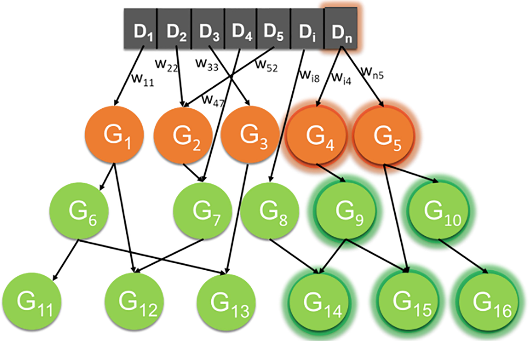
A diagram of what a representation of this type would look like is presented in Fig. 4. The robot starts with a drive vector defined by the designer. As it explores a domain or a set of different domains, it finds goals and relates them to the corresponding drive or drives that decreased their values when the goal was reached. Sometimes, certain skills acquired using cognitive drives over temporarily interesting state space points are needed to reach goals. Remember that these temporarily interesting points did not necessarily lead to the minimization of any operational drive, and, consequently, they were not proper goals. However, when they become steppingstones towards achieving a proper goal, we can upgrade them to the category of sub-goal and link them to the corresponding goal. Other ways to identify sub-goals and relate them to their associated goals have been proposed in the literature [50], but this is not the topic of this paper and we are not going to dwell on them. Suffice it to say that, whatever the approach used to identify sub-goals, they can be added to the drive-goal graph in order to represent their relationships.
Now, with regards to the first issue, that is, how to manage multiple drives and their interactions once a drive-goal graph is available, the solution can be very straightforward. Drive values are determined by the values of whatever sensors the designer has associated to them through the corresponding drive functions. Consequently, at any point in time, all the drives of a robot present a drive activation value. This value will be propagated down the drive-goal graph, activating those goals and sub-goals leading to the drive. This is shown in Fig. 4 where
These activations determine what goals and sub-goals are worth pursuing from the perspective and experience of the motivational structure within the cognitive architecture and, more importantly, to what extent. However, a choice of goals based only on these activation values does not consider the contextual aspects of the goal. That is, in what domain it was found and whether the robot is now operating in the same domain. Therefore, other components of the cognitive architecture that deal with context must come into play in order to filter out those goals that are not relevant. These mechanisms are cognitive architecture dependent. However, and as an example, in [35] we describe a Long-Term Memory (LTM) structure for the e-MDB cognitive architecture that provides the context related capabilities that are required through the use of context nodes.
Whatever the mechanism, this context related filtering will prune the drive-goal graph, leaving just those goals that are relevant in the current domain and situation. The cognitive architecture will choose the goal with the highest activation to guide the operation of the robot.
Of course, in the initial stages of development, in order to reduce active drives (both cognitive and operational), the robot will depend on the goals and associated utility functions the designer put in at design time. There may be many drives in the drive-goal graph without any goals connected to them as the robot has not found them in the domains it has faced. Consequently, when these drives are activated, the robot will have no idea on how they can be reduced. This is where the relevance of the cognitive drives becomes evident.
As indicated before, cognitive drives can be linked to predesigned goals and skills or utility models at design time. They only depend on the robot and not on the domains. In addition, cognitive drives are usually heterostatic, and thus, always present a certain level of activation (one can always seek more novelty). Hence, even when there are no active operational drives that the robot knows how to minimize, the cognitive drives will still be active. Consequently, the robot can pursue their pre-designed associated goals by following their designed-in expected utility models (or even designed-in associated policies).
Summarizing, by pursuing goals related to well-designed cognitive drives, some of which include designed-in goals and utility models, the robot explores the different domains it encounters, progressively learning to model them. While doing this, it finds operational goals that allow it to construct the drive-goal graph. In a hypothetical situation in which the robot has found goals that efficiently minimize all its drives when activated, there will be no need for exploration. An optimal stationary state in which any drive is immediately and efficiently minimized when it becomes active will have been reached. Obviously, in open-ended learning situations this will never be the permanent case, but it may happen for specific domains.
In order to illustrate the application of the concepts described up to this point, the following section deals with the construction of a minimal motivational system based these premises. The results of testing the performance of the system under different open-ended learning situations, both starting from scratch and when operating in populated drive-goal graph conditions, are also presented.
4.Experiments and analysis
The aim of this section is to show how, by designing a coherent set of robot drives, the designer can control the learning process as well as the behavior of the robot in different domains. This is the way to assign purpose to robots in open-ended learning situations, where the designer has no access at design time to the different goals the robot is going to find throughout its life.
4.1Materials and methods
We have considered a robot that must operate in an industrial scenario that implies several different domains. We, as designers, want the robot to assemble different parts of a piece in environments where there are human operators that can modify or interfere with its behavior. To simplify the study, and to focus on drive management, the state representation has been pre-defined.
Figure 5.
The left image corresponds to the pushing skill, while the right one corresponds to the grasping skill.
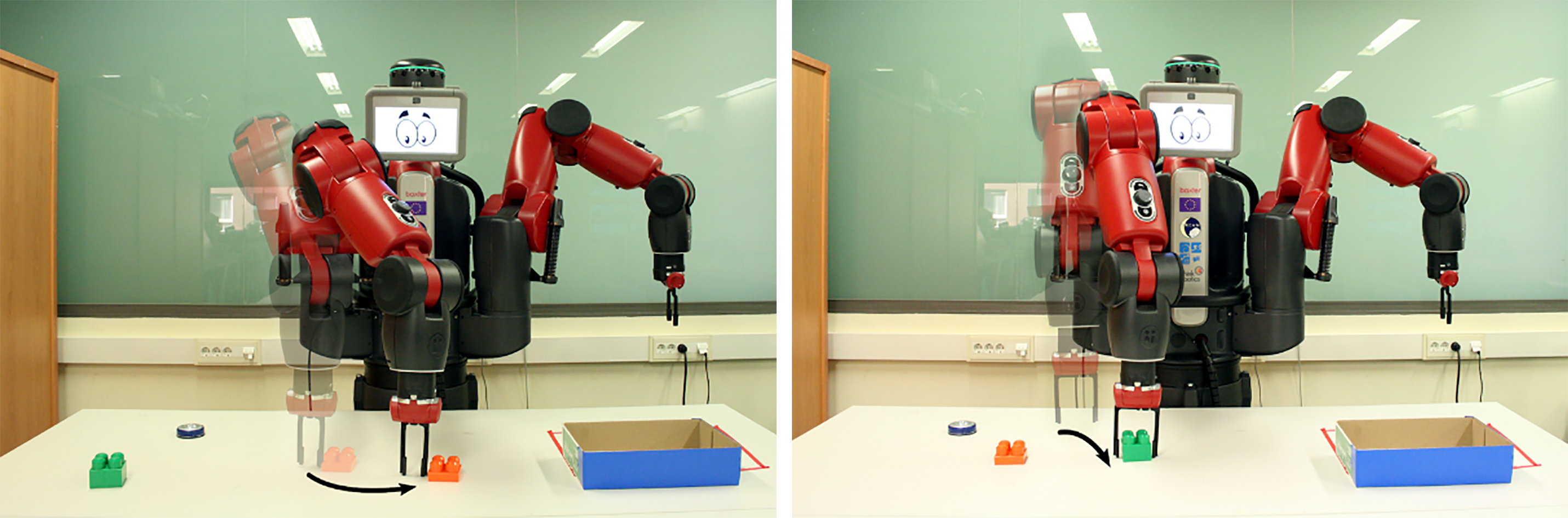
Figure 5 shows the experimental setup, which includes a Baxter robot placed in front of a table with different types of objects on it. The Baxter has two arms with 7 degrees of freedom each. The sensors used in the experiments are two RGB cameras, one on the head of the robot (used to detect the presence and position of human operators) and another on the ceiling of the room (in order to see the table that is located just in front of the robot), a brightness sensor in the ceiling camera that returns the ambient light level, and binary sensors in the grippers indicating whether they are holding something. The ceiling camera information was re-described in the form of a distance and angle to the center of the blobs corresponding to the objects. An attention mechanism that decides which of the blobs the robot focuses on has also been introduced. The velocity of the robot arm is computed as a sensor to estimate the correct movement. Finally, the YOLOv3 [51] identification algorithm is used to identify the objects, FaceNet [52] to identify people, and a convolutional neural network (CNN) based detector [53] was used for gesture recognition. To apply all these vision algorithms, we directly downloaded the pre-trained models included in the references with no adjustment from our side.
As explained in the previous section, an open-ended learning experiment can be divided into two different types of processes that will take place concurrently. Cognitive drive led processes will foster exploration and learning. Operational drive led processes will address the robot achieving its purpose. To show the operation of the drive management system proposed in this paper, the following two sub-sections consider two extreme cases. In the first one, we analyze the initial learning stages, where no operational goals have been found yet, to show how skills and models are learnt. In the second one, we consider a series of already well-known domains and analyze how the different drives interact to determine the behavior of the robot.
4.2Bootstrapping development using cognitive drives
The specific once interesting (
where
Figure 6.
Left:
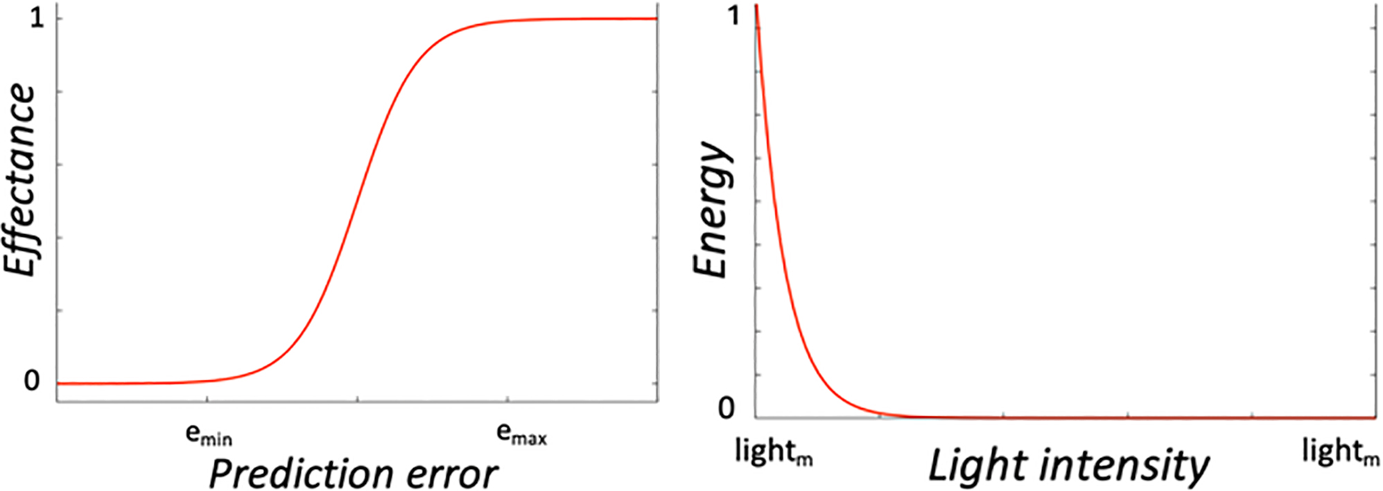
Regarding the
To induce training, the key aspect here is to try to make the robot reproduce the effect, that is, to reach the same state space point as often as possible. This creates samples to improve the world model making this effect more predictable and, also, selectable at will. To this end, we resort to the concept of “temporal goal” or “virtual goal”. That is, a goal that is only active until the system can consistently reach it.
Thus, when an effect is fortuitously produced for the first time, the point in state space where it occurred becomes a temporarily interesting type of goal. The associated activation of the goal will be related to the effectance drive value and, thus, to the world model error related to it. This activation will be initially high, thus making this goal salient and inducing the robot to try to obtain an expected utility model that leads towards it.
As this expected utility model becomes better, the robot will reach the virtual goal more often, producing samples that will help to improve the world model. This will lead to better predictions (lower prediction errors), reducing the activation of the virtual goal. The more proficient the robot becomes at achieving a goal, the less interesting this goal becomes.
Once the robot is very proficient, the skill for achieving the goal, in the form of a utility model, will have been acquired and it is stored in memory for future recall. It is important to mention that for this experiment both cognitive drives (novelty and effectance) have the same priority: their drive functions are weighed equally.
The experimental setup displayed in Fig. 5 has been created to test how these drives allow to autonomously learn new skills. It consists of four objects: a green and an orange block, a button, and a box. The green block can be grabbed, while the others are too small for the gripper to grasp them. All the objects may also be pushed around.
The robot started its operation without any explicit operational goal or skill apart from. It just had the two cognitive drives as well as pre-designed goals and policies for them. Thus, it started moving the right arm guided by the goal associated to
The drive is fulfilled if the robot consistently achieves the virtual goal, reducing its activation to zero. Therefore, the robot focused on finding ways to reach the goal point in state space from any initial point it found itself in. In this case, the robot started exploring how to make the orange block move. In parallel, it was progressively creating an expected utility model (ÛM) that allowed it to consistently move the block (push the block) by selecting actions that follow its positive gradient. Here, the ÛM were encoded as an ANN with 2 inputs (distance to the object and gripper velocity), 2 hidden layers of 5 neurons each, and 1 output (expected utility). The ANN parameters were adjusted on-line, through a stochastic gradient descent algorithm [55], using the samples the robot produced as training dataset.
As the ÛM improved, the robot became proficient in moving the orange blocks, and the world model used these samples to improve its predictions. This improvement led to a reduction in the activation of the
Figure 7.
Learnt ÛMs. Left: push. Right: grasp.
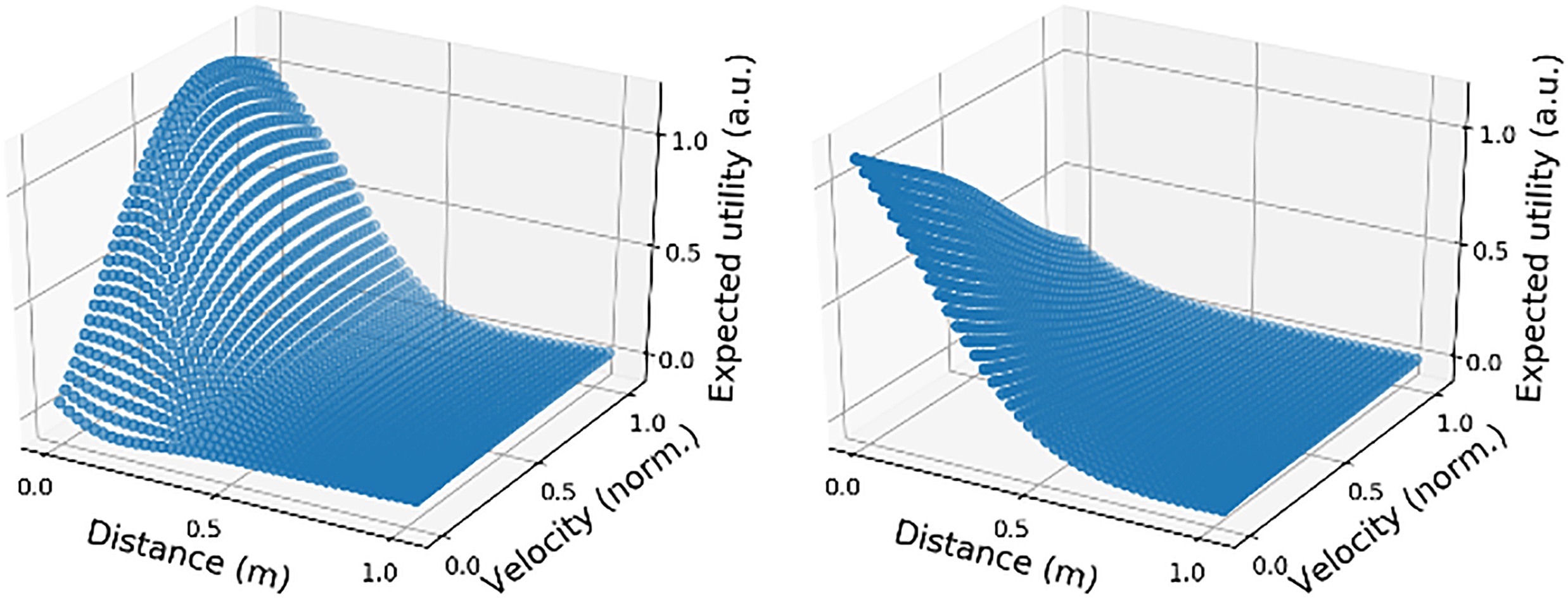
The robot continued using novelty guided exploration, until some object ended up between its gripper pads. This triggered a close gripper reflex action (displayed in the right image of Fig. 5), leading to a grasping behavior [56]. This action only caused an effect in the case of the green block, because the other blocks slip from the gripper.
Consequently, again, a previously unknown effect was detected and a virtual goal, with a high activation value propagated from the effectance drive, was assigned to it. As in the previous case, the
Summarizing, in this first stage of the experiment, guided only by cognitive drives, the system was able to learn two primitive skills (grasping and pushing) in a very efficient manner while it was autonomously interacting with the world. The ÛM corresponding to these skills are stored in LTM for later use by the architecture.
4.3 Some experiments dealing with operational drives
Let us now consider the case in which the robot has already learnt a series of goals with their associated utility models and policies following the procedures of the previous section. These are stored in LTM, where they are related to their contexts. These goals are also related to the drives they have minimized through a drive-goal graph the robot has constructed in previous exploration stages using cognitive drives, as explained in Section 4.2. In this case, in addition to the elements described in Section 4.1, the table over which the Baxter robot operates may contain different types of bricks, a button, a lamp, a delimited red area and a box.
The main purpose we want to instill the robot with is to assemble the different objects and place them in the predefined area while satisfying humans whenever they are present. During the experiment, at random times, we introduce different human operators, recognizable by the robot, to collect the assembled parts or to verify their correct assembly. Thus, when the operator in charge of verification approaches, he will only be satisfied if the robot shows him the assembled parts so that they can be verified. In the case of the operator who collects the assembled parts, he will only be satisfied when the box (brought by the operator) is full of assembled parts. Finally, since the robot works in a closed room and its correct operation depends on what it sees through its cameras, it needs to have a minimum level of illumination to be able to perform the tasks. Thus, when the light level is very low, the robot must seek to increase the light level.
Table 2
Policies available in LTM
| Policy | Description |
|---|---|
| Grasp_object | Use a gripper to grasp an object. |
| Ask_nicely | Ask experimenter for help. |
| Put_object_in | Place an object in a new position. |
| Push_object | Push an object to a chosen place. |
| Show_object | Grab an object and show it to a human. |
| Press_object | Use a gripper to press an object. |
As indicated at the beginning of this section, we are also assuming that a set of basic knowledge nuggets (policies, world models, utility models and goals), from previous interactions with different worlds and under different goals, are present in the LTM. A total of 6 possible policies (shown in Table 2) are available to the robot. Even though we are labeling these policies for clarity in the presentation, there are no such labels within the cognitive architecture.
As we want the robot to have a purpose, in addition to the two cognitive drives that were already presented in Section 4.2 (novelty and effectance), we need a drive related to this purpose. This operational drive (
Like any other drive,
where assembled_detector is a Boolean sensor that returns 1 if the blocks are assembled, and 0 if they are not, which is multiplied by another Boolean sensor (in_storage) that returns 1 when the assembled piece position is within the storage area and 0 otherwise. The temporal behavior of the drive is handled by resetting to 0 the two sensor values after the time point at which the drive is minimized (
Since we want the robot to heed the operators’ desires, there is also an innate operational drive related to human satisfaction (
This drive will affect the operation of the robot only when there are humans nearby. The reason being that when no humans are detected by the robot, the goals associated to this drive are contextually inhibited by the cognitive architecture, that is, the conditions for the possible activation of these goals are not met. Note that each operator may want different things, so this drive is not associated to the performance of a specific task, but to satisfying the human. This satisfaction is perceived using a gesture recognition sensor. When the human produces a thumbs up gesture, this sensor returns 1, otherwise, it returns 0.
Finally, we must define an energy drive (
Figure 8.
Drive-Goal graph for the experiment. The goals are defined in Table 3. Solid arrows represent the connections between drives, goals and sub-goals at the start of the experiment. The dashed arrow corresponds to a learnt relationship that is explained in Section 4.3.4.
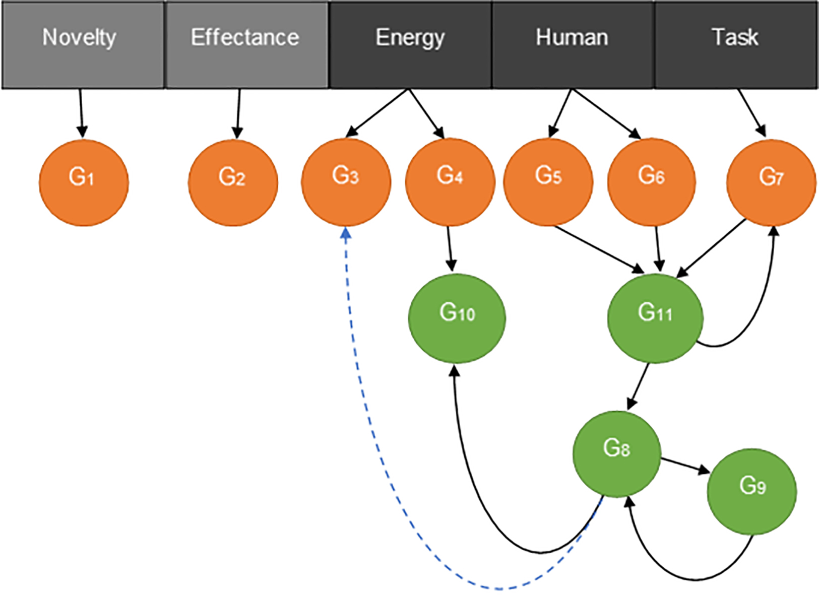
As a summary, Fig. 8 shows the drive-goal graph from which the experiments are going to start except for the dashed blue line, which will be explained later. The meaning of the goal labels can be found in Table 3. The direction of the arrows is the direction of propagation of activation (sub-goals receive from corresponding goal). The activation of a goal/sub-goal also depends on context and, therefore, a goal will not be activated if the context is not the appropriate one.
Table 3
Goals present in the LTM
Context pre-activation is carried out by other parts of the cognitive architecture that are not the object of this paper (an implementation can be found in [35]). In the experiments we will just provide an indication of what goals are inhibited by context dependent processing. This goal/sub-goal structure is not necessarily the final structure, it may change over time as we will see later.
Additionally, bear in mind that, as all drive values are normalized between 0 and 1, if we want the robot to give priority to certain drives, a weighting coefficient must be introduced. Here, the intention is for the robot to perform the assembly task but giving priority to satisfying humans and to maintaining an adequate level of light. Thus, the coefficients chosen for the operational drives were the following:
Figure 9.
Representation of the results obtained after the execution of the experiment during 400 time steps in 4 different scenarios for 7 different combinations of the coefficients. The number of assembled parts for each of the combinations is shown on the left, while the number of verified parts for each of these cases is shown on the right.
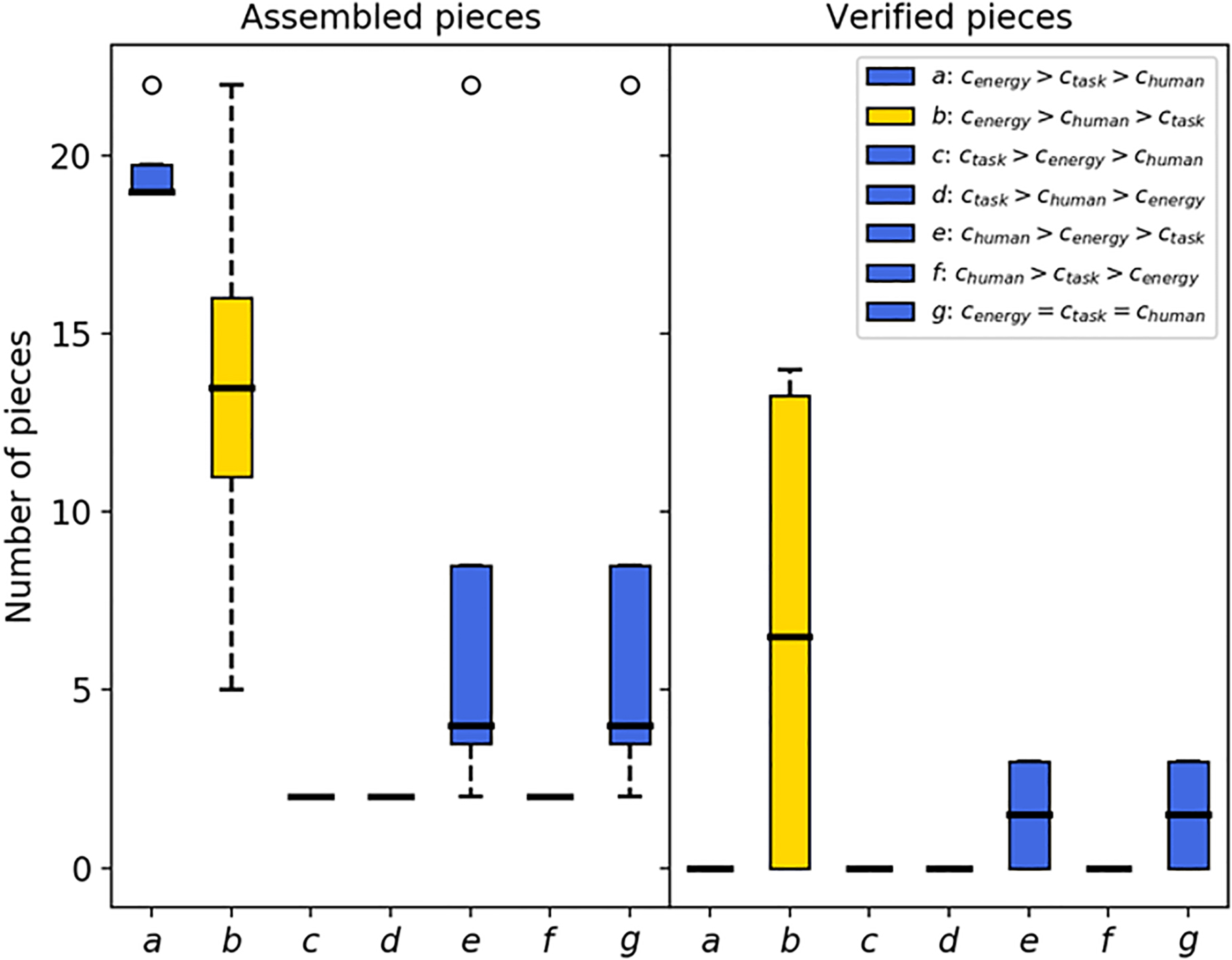
The values of the coefficients have been obtained from a parametric study over all the different combinations of coefficient values that affect the drives. The results are shown in Fig. 9. Keep in mind that what is important here is the order of drives induced by the coefficient values and not their absolute value. The same order will lead to the same behavior regardless of the specific values. Thus, 7 different parameter combinations (shown in the legend of Fig. 9) and 4 scenarios have been considered: no human operator appears, only the verification operator appears, only the collection operator appears, or both operators appear. To allow for the analysis of the robot’s performance, an external observer has kept track of the number of pieces of each type produced after each experiment.
In view of the results shown in Fig. 9, three different behaviors can be inferred. On the one hand, when
4.3.1Experiment design
Initially, we consider that the robot is in a room with an appropriate level of light that progressively decays and that there are no humans present. This first scenario is used to describe the operation of the robot following one drive and what happens when two drives interact (this occurs when the light level drops below a given threshold). Then, we will introduce different human operators at random points in time and analyze the interaction among the three main operational drives that come into play in this experiment. We will also show how context can help select only those goals that are associated to the domain the robot is currently facing. Finally, we will address a previously unseen situation in which no operational goals can be activated (the robot has run out of pieces on the table). We will show that this leads to cognitive drives taking control in order to find a new relevant operational goal. This operational goal is added to the drive-goal graph, allowing the robot to continue minimizing its operational drives.
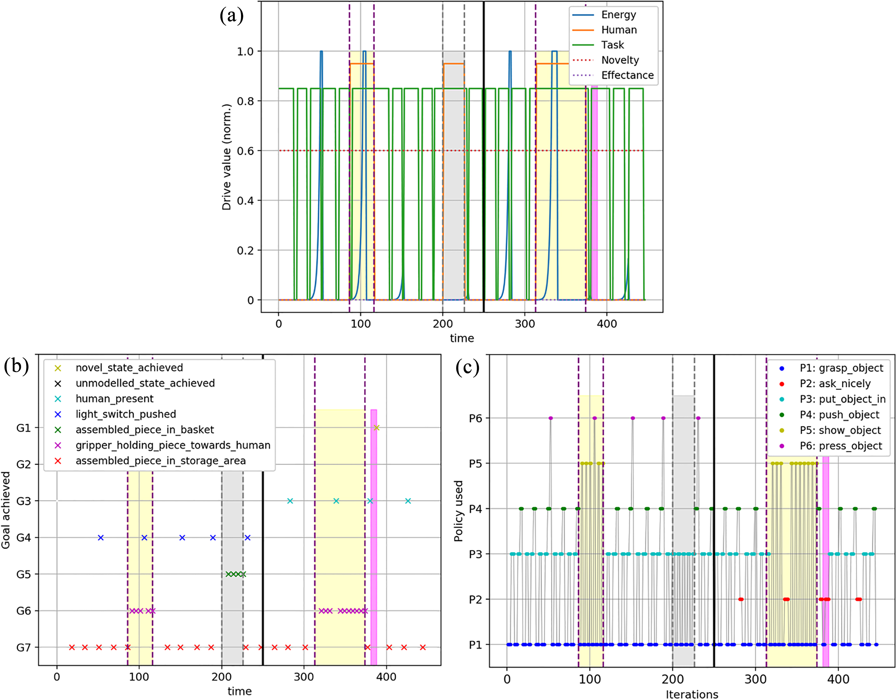
The evolution of the robot behavior over time is presented in Fig. 10, which contains three graphs with the data corresponding to a representative execution of the three stages of the experiment. Thus, Fig. 10a shows how the value of the different drives has varied over time. On the other hand, Fig. 10b shows what has happened in the environment (goal achievements) to minimize the drives of Fig. 10a. Both figures allow us to see how drives and goals come into play over time. That is, when a drive is activated to a higher level than the rest, the robot seeks to achieve its associated goals.
Finally, to provide more details of what is happening in the environment, Fig. 10c shows the different policies that have been chosen over time to achieve the goals. These policies come from the set described in Table 2. For clarity when analyzing the behavior of the robot in this environment, the figures have been divided into different parts. Thus, the moments in which human operators are seen by the robot are shaded and between vertical dotted lines. The area marked in gray indicates the presence of the operator in charge of collecting assembled parts, whereas the area marked in yellow indicates that the operator is the one in charge of verification.
Figure 10.
Evolution of the drive values over time. (b) Goals achieved over time. (c) Policies used over time.
4.3.2Initial operation
When the experiment begins, at which point no humans are present and the light level is high, Fig. 10a shows that the only drive with a value greater than zero is the one corresponding to the assembly task to be performed by the robot. Thus, and as discussed in Section 3.3, its activation propagates down the drive-goal graph, activating the goals and sub-goals associated to the drive that are not inhibited by context.
Looking at Fig. 10c, it can be seen how the robot executes the policies corresponding to the assembly task. It first grasps a green object and places it on the mounting area located in the center of the table, then grabs the second object and places it on top of the green one and, finally, moves the assembled piece to the storage area. This means that goal
Note that the execution of the ‘grasp_object’ and ‘put_object_in’ policies do not always have the same duration in time, while ‘push_object’ does. This is because the pieces to assemble can be placed in different positions on the table, making the time needed to pick them up and place them dependent on the distance from the robot arm to the piece.
Once the piece has been assembled, if we look again at what happens in Fig. 10a, none of the other drives have changed their value, but after some instants of time, the activation of the task drive increases again as the effect of the previous assembly on the drive fades. This is repeated until, at time 50, the light level in the room has decreased down to a point where the drive with the highest activation, that is, the one that takes control, is the energy drive. The activation of this drive will propagate through the drive-goal graph causing its associated goals to be activated.
Figure 10c shows how the policy executed by the robot is ‘push_object’, which, as shown in Fig. 10b, leads to reaching goal
Looking closely at Fig. 10a, it is possible to see how, depending on the value of the rest of the drives, the robot turns on the light before or after reaching the drive limit. Thus, in instants of time 150, 230 and 380, the drive is minimized at the very moment in which its value begins to increase, because it is the moment in which a new part has just been assembled and the task drive activation value is low. On the contrary, at other times it is necessary to reach a value for this drive that is high enough for it to surpass all other drives and take control. Thus, for example, in instants of time 110 and 340, despite the human operator being present, the robot abandons what it is doing in order to maintain an adequate level of light.
4.3.3Domain changes
Let us analyze what happens when the human satisfaction drive comes into play, that is, when human operators are detected by the robot. This is, in fact, an example of domain change, as different operators imply different goals and policies.
The operator in charge of the verification of assembled parts is detected for the first time around time step 85. The appearance of a human means that, at that point, the drive with the highest activation value is the human drive, which takes control of the robot. Its activation value is propagated along the drive-goal graph making any of the goals associated with it more active than the rest. However, considering only the motivational drive-goal graph, there would be two contradictory active goals: one having to do with verification, and another one with assembled piece collection. In this case, the perception of the robot (through its face recognition component) allows it to establish that the human is the one in charge of verification. Consequently, the context component of the architecture will inhibit those goals that are not related to the verification operator leaving only
In this instance, as the robot was already executing the last policy corresponding to the assembly task (‘push_object’), the assembled piece goal is reached, and its associated drive is minimized just when the human arrives. From that point on, the robot will begin to show the operator the pieces that were assembled and stored in the storage area one by one through the combination of the ‘grasp_object’ and ‘show_object’ policies. In turn, as each piece is verified, the robot achieves the piece verification goal (Fig. 10b). However, only when all the pieces have been verified, does the human operator perform a gesture of approval to the robot, which reduces the human drive. At that point, the operator also leaves the room, which is marked by the second vertical dotted line. Figure 11 shows the robot finishing the verification task and the operator (upper left corner of the figure) making the approval gesture mentioned above.
Figure 11.
At the end of the verification task the operator (inset image shows the view from the robot front-facing camera) makes a gesture of approval to the robot.
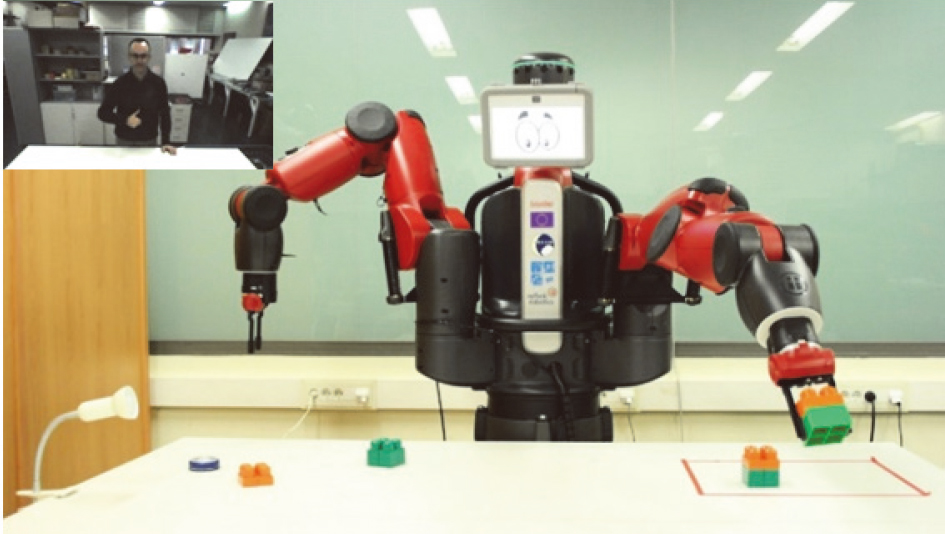
Figure 10b and c show that the number of pieces that have been verified coincides with the number of pieces that have been assembled up to that point, since both goals,
After the first operator leaves, the robot continues its normal operation assembling parts and turning on the lamp when necessary. This happens until the operator in charge of collecting the assembled pieces approaches and is detected at time 200. This makes the human drive increase in value (indicated in Fig. 10 by another vertical dotted line, now with gray shading).
Figure 12.
The robot executes the ‘place_object_in’ policy to achieve the ‘assembled_piece_in_basket’ goal.
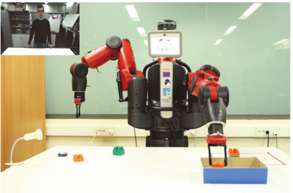
Figure 12 displays how the robot performs the task of filling the basket while the new operator (upper left corner) waits for it to be full to give the robot a gesture of approval leading to a reduction in the value of the drive. This happens at time
In order to consider a more explicit domain change, the button that allows the light to be turned on by the robot can be removed. This implies that the robot cannot achieve goal
Summarizing, different domains usually imply different goals associated to the same drive. The context determination part of the cognitive architecture inhibits all the goals that have not been learnt in the domain the robot is currently facing. Consequently, the propagation of the drive activation level will only activate those goals that are contextually relevant and, out of those, the one with the highest activation will be pursued.
4.3.4Learning new tricks
Finally, we are interested in analyzing what happens when the robot encounters an unexpected situation in which there is no active goal that allows reducing its active drives. To this end, we have considered a situation in which, after the second human operator leaves for the second time (time
Looking at Fig. 10a, we see that what happens is that, even though the task drive is the one with the highest activation, as it has no available goals to be pursued. The goals with the highest activation are those related to the novelty drive, which, by the way, is always active to a certain level as it is a heterostatic cognitive drive. Consequently, the goals and policies associated to the novelty drive take control of the robot indirectly inducing an exploration of the operational state space. In this case, what happens, according to what is shown in Fig. 10c (area shaded in pink), is that the robot begins to randomly test policies trying to reach novel states. Eventually, this search leads to the robot applying the ‘ask_nicely’ policy, which makes an operator come, evaluate the situation and notice that the robot needs a new set of unassembled components on the table. Once the operator has introduced the new set of components, some of the goals in the path towards
What is important here is that when
5.Conclusions
The problem of creating robots for lifelong open-ended operation has seldom been addressed from a design point of view. That is, from the perspective of being able to design how the robot should go about learning and behaving in the different – a priori unknown – domains it will face throughout its lifetime, so that these behaviors serve the purposes of the designer.
In this paper, we have proposed an approach to achieve this goal based on a specific understanding and formalization of motivation in robotics. The formalization involves two types of designer defined robot needs together with their associated designer defined drive functions: cognitive needs and operational needs. A methodology to design the need-drive system, as well as an operational mechanism that allows for the selection of previously learnt goals and skills, were proposed and tested on an experiment over a real robot. The design methodology is based on the balancing of the drive functions of a combination of operational needs with once interesting and temporarily interesting cognitive needs. The operational mechanism involves a drive-goal tree that is constructed as the robot interacts with different domains and that permits selecting goals as a function of drive activation and context.
The experiments that were carried out have shown that, through an appropriate selection of operational needs-drives, the purpose of the robot can be clearly designed in. In addition, by crafting adequate cognitive needs-drives, the designer can make the robot successfully explore new domains, learning their operation and efficiently finding goals and learning skills to exploit them so that its operational needs are satisfied, that is, to achieve its purpose. In fact, we have also shown how temporarily interesting cognitive drives can allow for learning skills that may not be related to immediate operational drive satisfaction, but that may be used as steppingstones to fulfill operational needs later on. Finally, the results confirm that by manipulating the relative levels associated to the different operational drives through the scaling of their drive functions, different purposes can be instilled on the robot very easily.
One of the main insights with regards to the design of the motivational system is that cognitive needs-drives are defined in state space that is internal to the robot and thus, independent of any domain the robot may encounter. This opens the possibility of the designer being able to design-in efficient strategies (policies, utility models, etc.) associated to fulfilling cognitive needs. This was, in fact, shown in the experiments, where novelty and effectance cognitive needs-drives were designed in together with their associated utility models and search strategies. This allowed for a much more efficient and controlled operation of the system.
With respect to future work, we are currently designing a simple strategy for the autonomous regulation of multiple drives in order to optimize long-term operation. In addition, it would be interesting to work on the extension of the proposal to the case in which some (operational) drives are continuous in their satisfaction levels, as the combination of drives with continuous and discrete satisfaction levels is a much more realistic scenario.
Acknowledgments
This work was partially funded by the EU’s H2020 research programme (grant No 640891 DREAM), Ministerio de Ciencia, Innovación y Universidades of Spain/FEDER (grant RTI2018-101114-B-I00), Xunta de Galicia and FEDER (grant ED431C 2017/12), and by the Spanish Ministry of Education, Culture and Sports through the FPU grant of Alejandro Romero.
References
[1] | Chen X, Zhao B, Wang Y, Xu S, Gao X. Control of a 7-DOF Robotic Arm System with an SSVEP-Based BCI. Int J Neural Syst. (2018) ; 28: (8): 1850018. |
[2] | Wang X, Zhang G, Neri F, Zhao J, Gheorghe M, Ipate F, et al. Design and implementation of membrane controllers for trajectory tracking of nonholonomic wheeled mobile robots. Integr Comput Aided Eng. (2016) ; 23: : 15-30. |
[3] | Paredis CJJ, Benjamin Brown H, Khosla PK. A rapidly deployable manipulator system. Rob Auton Syst. (1997) ; 21: (3): 289-304. |
[4] | Almagro-Cadiz M, Fresno V, De la Paz Lopez F. Speech gestural interpretation by applying word representations in robotics. Integr Comput Aided Eng. (2019) ; 26: (1): 97-109. |
[5] | Pellegrinelli S, Pedrocchi N. Estimation of robot execution time for close proximity human-robot collaboration. Integr Comput Aided Eng. (2018) ; 25: : 81-96. |
[6] | Caruana R, Niculescu-Mizil A. An empirical comparison of supervised learning algorithms. In: Proceedings of the 23rd international conference on Machine learning. (2006) , pp. 161-8. |
[7] | Sutton RS, Barto AG. Introduction to Reinforcement Learning. Learning [Internet]. (1998) ; 4: (1996): 1-5. Available from: lhttp//dl.acm.org/citation.cfm?id=551283. |
[8] | Florea AG, Buiu C. A distributed approach to the control of multi-robot systems using XP colonies. Integr Comput Aided Eng. (2018) ; 25: (1): 15-29. |
[9] | Ramos F, Vázquez AS, Fernández R, Olivares A. Ontology Based Design, Control and Programming of Modular Robots. Integr Comput Aided Eng. (2018) ; 25: (2): 173-92. |
[10] | Doncieux S, Filliat D, Diaz-Rodriguez N, Hospedales T, Duro R, Coninx A, et al. Open-ended learning: A conceptual framework based on representational redescription. Front Neurorobot. (2018) ; 12: . |
[11] | Thrun S, Mitchell TM. Lifelong robot learning. Rob Auton Syst. (1995) ; 15: (1-2): 25-46. |
[12] | Weng J, McClelland J, Pentland A, Sporns O, Stockman I, Sur M, et al. Autonomous mental development in robots and animals. Science (80-). 2001: ; 291: : 599-600. |
[13] | Asada M, Hosoda K, Kuniyoshi Y, Ishiguro H, Inui T, Yoshikawa Y, et al. Cognitive Developmental Robotics: A Survey. IEEE Trans Auton Ment Dev [Internet]. (2009) ; 1: (1): 12-34. Available from: http//ieeexplore.ieee.org/lpdocs/epic03/wrapper.htm?arnumber=4895715. |
[14] | Asada M, MacDorman K, Ishiguro H. Cognitive developmental robotics as a new paradigm for the design of humanoid robots. Robot [Internet]. (2001) [cited 2012 Feb 3]; 37: : 185-93. Available from: http//www.sciencedirect.com/science/article/pii/S0921889001001579. |
[15] | Piaget J, Cook M. The origins of intelligence in children. New York: New York: International Universities Press, (1952) . |
[16] | Thelen E, Fisher DM. The organization of spontaneous leg movements in newborn infants. J Mot Behav. (1983) ; 15: (4): 353-72. |
[17] | Hull CL. Principles of Behavior. New York: Appleton-Century-Crofts, (1943) . |
[18] | Maslow AH. A theory of human motivation. Psychol Rev. (1943) ; 50: (13): 370-96. |
[19] | Locke EA, Latham GP. Goal setting theory. Motiv Theory Res. (1994) ; 13-29. |
[20] | White RW. Motivation reconsidered: the concept of competence. Psychol Rev. (1959) ; 66: (5): 297. |
[21] | Baldassarre G, Mirolli M. Intrinsically motivated learning in natural and artificial systems. In: Intrinsically Motivated Learning Systems: an Overview [Internet]. Springer Berlin Heidelberg; (2013) , pp. 1-14. Available from: http//www.scopus.com/inward/record.url?eid=2-s2.0-84929047179&partnerID=40&md5=66fe11c06619bf5271e6ea3c05e5a2fa. |
[22] | Oudeyer P, Baranes A, Kaplan F. Intrinsically Motivated Learning of Real-World Sensorimotor Skills with Developmental Constraints. Intrinsically Motiv Learn Nat Artif Syst [Internet]. (2013) ; 303-365. Available from: http//link.springer.com/chapter/10.1007/978-3-642-32375-1_13. |
[23] | Singh SP, Lewis RL, Barto AG, Sorg J. Intrinsically Motivated Reinforcement Learning: An Evolutionary Perspective. IEEE Trans Auton Ment Dev [Internet]. (2010) ; 2: (2): 70-82. Available from: 10.1109/TAMD.2010.2051031. |
[24] | Oudeyer P, Hafner VV, Whyte A. The Playground Experiment: Task-Independent Development of a Curious Robot. In: Proc AAAI Spring Symposium on Developmental Robotics. (2005) , pp. 42-7. |
[25] | Mirolli M, Santucci VG, Baldassarre G. Phasic dopamine as a prediction error of intrinsic and extrinsic reinforcements driving both action acquisition and reward maximization: A simulated robotic study. Neural Networks. (2013) ; 39: (March 2016): 40-51. |
[26] | Wigfield A, Eccles JS. Expectancy-value theory of achivement motivation. Contemp Educ Psychol [Internet]. (2000) ; 25: (1): 68-81. Available from: http//www.ncbi.nlm.nih.gov/pubmed/10620382%5Cnhttp://www.sciencedirect.com/science/article/pii/S0361476X99910159. |
[27] | Prieto A, Romero A, Bellas F, Salgado R, Duro RJ. Introducing Separable Utility Regions in a Motivational Engine for Cognitive Developmental Robotics. Integr Comput Aided Eng. (2019) ; 26: (1): 3-20. |
[28] | Romero A, Bellas F, Becerra JA, Duro RJ. Bootstrapping Autonomous Skill Learning in the MDB Cognitive Architecture. In: Ferrandez Vicente JM, Alvarez Sanchez JR, De la Paz Lopez F, Toledo Moreo J, Adeli H, editors. Ferrandez Vicente JM, Alvarez-Sanchez JR, de la Paz Lopez F, Toledo Moreo J, Adeli H, Eds, Understanding the Brain Function and Emotions, Proceedings of the 8th International Work-Conference on the Interplay Between Natural and Artificial. Springer, (2019) , pp. 120-9. |
[29] | Barto AG. Intrinsic motivation and reinforcement learning. In: Intrinsically Motivated Learning in Natural and Artificial Systems, Springer Berlin Heidelberg, (2013) , pp. 17-47. |
[30] | Huang X, Weng J. Value system development for a robot. IEEE Int Conf Neural Networks – Conf Proc. (2004) ; 4: : 2883-8. |
[31] | Merrick KE. A comparative study of value systems for self-motivated exploration and learning by robots. IEEE Trans Auton Ment Dev. (2010) ; 2: (2): 1-15. |
[32] | Starzyk JA. Motivated Learning for Computational Intelligence. In: Computational Modeling and Simulation of Intellect: Current State and Future Perspectives [Internet]. IGI Global; (2011) , pp. 265-92. Available from: http//www.ohio.edu/ people/starzykj/network/research/Papers/Motivated Learning for Computational Intelligence.pdf. |
[33] | Hawes N. A survey of motivation frameworks for intelligent systems. Artif Intell. (2011) ; 175: (5-6): 1020-36. |
[34] | Rolf M, Asada M. “What are goals? And if so, how many”, In: Proc Joint IEEE International Conference on Development and Learning and Epigenetic Robotics (ICDL-EpiRob). (2015) , pp. 332-9. |
[35] | Duro RJ, Becerra JA, Monroy J, Bellas F. Perceptual generalization and context in a network memory inspired long term memory for artificial cognition. Int J Neural Syst. (2019) ; 29: (6): 1850053. |
[36] | Taylor ME, Stone P. Transfer learning for reinforcement learning domains: A Survey. J Mach Learn Res [Internet]. (2009) ; 10: : 1633-85. Available from: http//portal.acm.org/citation.cfm?id=1755839. |
[37] | Ryan RMR, Deci EL. Intrinsic and extrinsic motivations: Classic definitions and new directions. Contemp Educ Psychol [Internet]. (2000) ; 25: (1): 54-67. Available from: http//www.ncbi.nlm.nih.gov/pubmed/10620381: : |
[38] | Nocera D Finzi A, Rossi S, Staffa M. The role of intrinsic motivations in attention allocation and shifting. Front Psychol. (2014) ; 5: : 273. |
[39] | Ryan R, Deci E. Intrinsic and Extrinsic Motivations: Classic Definitions and New Directions. Contemp Educ Psychol [Internet]. (2000) ; 25(1): 54-67. Available from: http//www.ncbi.nlm.nih.gov/pubmed/10620381. |
[40] | Harlow HF. Learning and satiation of response in intrinsically motivated complex puzzle performance by monkeys. J Comp Physiol Psychol. (1950) ; 43: (4): 289. |
[41] | Baldassarre G, Stafford T, Mirolli M, Redgrave P, Ryan R, Barto A. Intrinsic motivations and open-ended development in animals, humans, and robots: An overview. Front Psychol. (2014) ; 5: (AUG): 985. |
[42] | Oudeyer PY, Kaplan F. What is intrinsic motivation? A typology of computational approaches. Front Neurorobot. (2009) ; 1: : 6. |
[43] | Huang X, Weng J. Novelty and Reinforcement Learning in the Value System of Developmental Robots. In: Proceedings Second International Workshop on Epigenetic Robotics [Internet]. (2002) , pp. 47-55. Available from: http//cogprints.org/2511/. |
[44] | Burda Y, Edwards H, Pathak D, Storkey A, Darrel T, Efros A. Large-scale study of curiosity-driven learning. ArXiv Prepr. 2018; 1808.04355. |
[45] | Forestier S, Mollard Y, Oudeyer P. Intrinsically motivated goal exploration processes with automatic curriculum learning. ArXiv Prepr. 2017; 1708.02190. |
[46] | Barto A, Mirolli M, Baldassarre G, Nathan F. Novelty or Surprise? Front Psychol. (2013) ; 4: (December): 907. |
[47] | Schembri M, Mirolli M, Baldassarre G. Evolving internal reinforcers for an intrinsically motivated reinforcement-learning robot. In: 2007 IEEE 6th International Conference on Development and Learning. IEEE; (2007) , pp. 282-7. |
[48] | Gatsoulis Y, McGinnity TM. Intrinsically motivated learning systems based on biologically-inspired novelty detection. Rob Auton Syst. (2015) ; 68: : 12-20. |
[49] | Berseth G, Geng D, Devin C, Finn C, Jayaraman D, Levine S. SMiRL: Surprise Minimizing RL inDynamic Environment. ArXiv: 191205510v1, (2019) . |
[50] | Menache I, Mannor S, Shimkin N. Q-Cut – Dynamic Discovery of Sub-Goals in Reinforcement Learning. In: Proceedings of the 13th European Conference on Machine Learning, (2002) , pp. 295-306. |
[51] | Redmon J, Farhadi A. YOLOv3: An Incremental Improvement [Internet]. Pre-trained model available: https://pjreddie.com/darknet/yolo. (2018) ; Available from: https//pjreddie.com/media/files/papers/YOLOv3.pdf. |
[52] | Schroff F, Kalenichenko D, Philbin J. FaceNet: A unified embedding for face recognition and clustering. In: 2015 IEEE Conference on Computer Vision and Pattern Recognition (CVPR) Pre-trained model available at: https//github.com/davidsandberg/facenet: Boston, MA; (2015) , pp. 815-23. |
[53] | Borba F. Tutorial: Using Deep Learning and CNNs to make a Hand Gesture recognition model [Internet]. Towards data Science. (2019) , Available from: https://towardsdatascience.com/tutorial-using-deep-learning-and-cnns-to-make-a-hand-gesture-recognition-model-371770b63a51. Pre-trained model available: https//github.com/filipefborba/HandRecognition. |
[54] | Salgado R, Prieto A, Bellas F, Calvo-Varela L, Duro RJ. Motivational engine with autonomous sub-goal identification for the Multilevel Darwinist Brain. Biol Inspired Cogn Archit. (2016) ; 17: : 1-11. |
[55] | Kingma D, Ba J. ADAM: A method for stochastic optimization. ArXiv14126980; – Code available https//keras.io/optimizers/. (2014) . |
[56] | Price A, Balakirsky S, Christensen H. Robust grasp preimages under unknown mass and friction distributions. Integr Comput Aided Eng. (2018) ; 25: (2): 111-35. |

