
A novel method for gas mixing and distribution in multi-chamber embryo incubators
Abstract
BACKGROUND:
High-quality control of the gas environment in incubators is crucial for in vitro embryo development, which requires high accuracy, fast recovery, and low gas consumption.
OBJECTIVE:
In this study, we propose a novel gas mixing and distribution system and method as an alternative solution for multi-chamber embryo incubators.
METHODS:
The system-based embryo incubator enables a controllable gas circulation process and a quantitative supply of CO2 and N2. To determine the optimal parameters for the mixing time and flow rate of the circulated gases, we conducted contrast experiments on the system-based incubator. To evaluate the performance of the gas system in the incubator, we conducted tests under four different initial conditions, simulating various practical application scenarios. Furthermore, we performed a mouse embryo assay to assess the system’s effectiveness.
RESULTS:
The results show that the system achieved a gas concentration accuracy of
CONCLUSION:
The system and method demonstrate a significant advantage in terms of low gas consumption compared to existing incubators, while still maintaining high accuracy and fast recovery.
1.Introduction
Regulating the media, temperature, humidity, and gas mixture in the in vitro biochemical environment is crucial for cell growth and development. Among these factors, the gas mixture plays a significant role in maintaining the pH of the media at an appropriate level [1]. Generally, most cells should be cultured in a 5% CO2 and air environment [2]. However, embryos grow best under a gas environment containing 6% CO2, 5% O2, and 89% N2 as widely reported. Several studies have shown that a low oxygen concentration of 5% can enhance oocyte maturation and blastocyst development, achieving a higher potential for ongoing clinical pregnancy [3, 4, 5, 6].
Conventional water jacket incubators (Thermo Fisher Forma 3110, ASTEC WMI-165) are originally designed for large-scale somatic cell culture and have an internal volume of about 180 L. These incubators use CO2 and O2 sensors to measure the concentrations of mixed gases and employ a fan to promote mixing to achieve the desired concentrations. However, when the door is closed, it takes more than 120 minutes for these incubators to recover the gas concentrations, resulting in high gas consumption [7]. As an alternative technology, multi-chamber embryo incubators have gained popularity in IVF (in vitro fertilization) laboratories. These incubators have superior temperature and gas control capabilities [7, 8, 9]. The individual chamber design of these incubators offers significant advantages over conventional methods in terms of temperature and gas recovery. Due to their smaller interior volume, the temperature and gas levels in these incubators typically reach equilibrium within one minute and three minutes, respectively, after any disturbance, and then stabilize at the setpoint [7].
Multi-chamber benchtop incubators can be categorized into two types based on the gas supply mode [10]: one is supplied with a medical grade pre-mixed gas containing 6% CO2, 5% O2, and 89% N2 (Genea Biomedex Geri) [11], while the other is supplied with pure CO2 and pure N2 (ESCO Medical Miri TL) [12]. In the former case, the gas is released into each individual chamber through a solenoid valve and then vented directly to the atmosphere, leading to higher gas consumption compared to the circulation system. Additionally, the stability of gas concentration in the cylinder is influenced by various factors, including ambient temperature. In the latter case, an air pump is used to drive the gas, achieving mixing and distribution through circulation. The automatic program enables the regulation of gas to reach any desired setpoint, typically ranging from 3–10% for CO2 and 5–20% for O2, to accommodate different culture requirements. The gas consumption under normal conditions, as per the standard operating procedure, is less than 2 L/h for CO2 and 5 L/h for N2, which is considered suboptimal. Moreover, using a single air pump, the incubator cannot guarantee uniformity of gas across all chambers due to the flow resistance differences between channels. Therefore, further optimization of existing gas systems in multi-chamber incubators is necessary to improve concentration accuracy, recovery time, environmental uniformity, gas consumption, gas purification, and minimize disturbance to embryos.
To explore a better solution for addressing the limitations of the gas system in a multi-chamber incubator, we propose a novel gas mixing and distribution system, along with a theoretical method for calculating the inflow volume of the two supply gases. Through conducting experiments and optimizing the system parameters, we demonstrate that the system-based incubator achieves high accuracy and fast recovery, while also significantly reducing gas consumption. The system and method presented in this study can serve as a valuable reference for the development of multi-channel gas distribution systems in various applications.
2.Materials and methods
2.1Gas mixing and distribution system
The proposed system of gas mixing and distribution is illustrated in Fig. 1. Two MFCs are used to accurately regulate the flow rate and volume of CO2 and N2 from the cyliders to the gas mixer [13, 14]. The gas mixer is used to achieve gas mixing within the system [15, 16]. The system consists of twelve individual chambers, each connected to a micro air pump and a check valve. The air pumps are used to drive gas flow and circulation in the system, as well as distribute gas to the chambers. The check valve prevents air interference when a chamber lid is opened. The state of each chamber lid (open or closed) can be identified by a switch sensor. The gas, propelled by the air pumps, flows from the mixer into the chambers and then returns back to the mixer to achieve circulation, as indicated by the red arrows in Fig. 1. The air pump is automatically deactivated when chamber lid is open and only operates when the chamber lid is closed. Consequently, the gas circulation part remains enclosed as long as at least one chamber lid is closed. The gas sensor is positioned downstream of the gas mixer and upstream of the chambers, along the flow direction, to measure the gas concentrations (volume fraction). Additionally, a relief valve, positioned between the gas sensor and the check valves, serves as a crucial component. Its purpose is to release any excess gas when the internal pressure exceeds atmospheric pressure.
Figure 1.
Schematic of the gas mixing and distribution system for a multi-chamber embryo incubator. The red arrows indicate the gas flow direction.
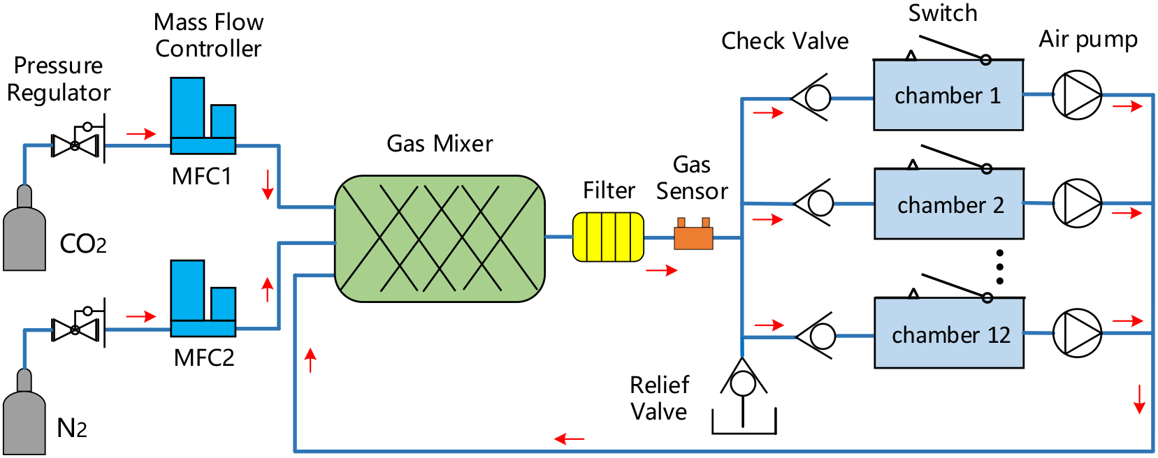
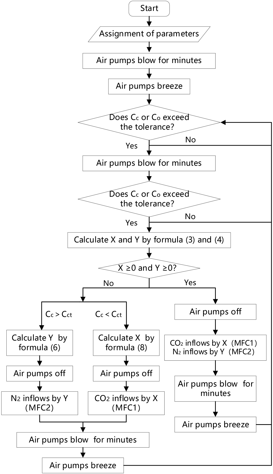
The standard operation process of the system starting from the initial gas condition consists of the following four stages:
(1) All the air pumps blow at a high flow rate for several minutes, promoting rapid gas flow and mixing through the gas mixer. This process also ensures the distribution of gas throughout the chamber. Mixing is performed to minimize the gas concentration gradient and achieve a consistent gas concentration throughout the system. The effect of gas mixing over time can be evaluated by measuring the concentrations.
(2) If the measured gas concentrations after mixing fall outside the acceptable range, the MFCs will control the flow of CO2 and N2 separately into the gas mixer at specific volumes. At the same time, the original gas in the mixer is slowly discharged through the relief valve until the MFCs are closed. It is important to note that a small quantity of new gas may also escape during this process. The inflow volume of CO2 and N2 can be calculated based on system parameters and measured gas concentrations. Additionally, it is crucial to keep the air pumps closed during this stage to ensure thorough replacement of the original gas with the new gas.
(3) Similar to stage 1, all the air pumps are activated to blow for several minutes, to facilitate the mixing of the new gas with any remaining original gas. The goal is to achieve a high level of uniformity in gas concentration throughout the entire system.
(4) All the air pumps are set to a low flow rate, known as breezing, to prevent air leakage into the chamber and potential impact on cell development. This breezing state continues as long as the lid remains closed, unless there is a change in gas concentration. When the lid is opened and closed again, a blowing operation is initiated instead of breezing, allowing the system to quickly return to the previous level within a short period, usually within three minutes.
In summary, the system raises two main concerns: determining the optimal mixing parameters and calculating the inflow volume of CO2 and N2.
2.2Calculation of inflow volume
The method for calculating the theoretical inflow volume of CO2 or N2 passing through the MFC can be derived using the following approach. For a single gas in the circulation part, the calculation involves adding the volume of the original gas to the volume of the newly introduced gas and then subtracting the volume of the gas discharged from the relief valve. This resulting volume should be equal to the product of the total volume of the circulation part and the target concentration. Therefore, the calculation for the inflow volume of CO2 or N2 passing through the MFC can be represented as:
(Volume of original gas
Consequently, the inflow volume of CO2 and N2 satisfies the following equations, respectively:
(1)
(2)
where V is the total volume of the circulation part, Cc and Co are the current concentrations of CO2 and O2, X and Y are the inflow volume of CO2 and N2, Cct and Cot are the target concentrations of CO2 and O2, respectively. The gas concentrations are expressed by volume fraction.
Thus, the X and Y can be calculated as follows:
(3)
(4)
When X and Y are both positive, the result indicates a feasible solution that the target concentrations of CO2 and O2 can be achieved by injecting the corresponding volume of CO2 and N2. Otherwise, there are no feasible solutions, which results from the reason Co
(1) For Cc
(5)
The new Y can be calculated as follows:
(6)
(2) For Cc
(7)
The new X can be calculated as follows:
(8)
The workflow of the gas mixing and distribution system, along with the operation process and calculation method of inflow volume, is illustrated in Fig. 2. This workflow serves as the basis for developing an automatic control program for a multi-chamber incubator.
Figure 2.
Flow chart of gas mixing and distribution system.
2.3System-based incubator and experiment
Figure 3.
A system-based multi-chamber time-lapse embryo incubator. (a) Layout of the relevant components of the gas system. (b) The control structure of the incubator. The gas mixing and distribution system is circled with a dashed line.
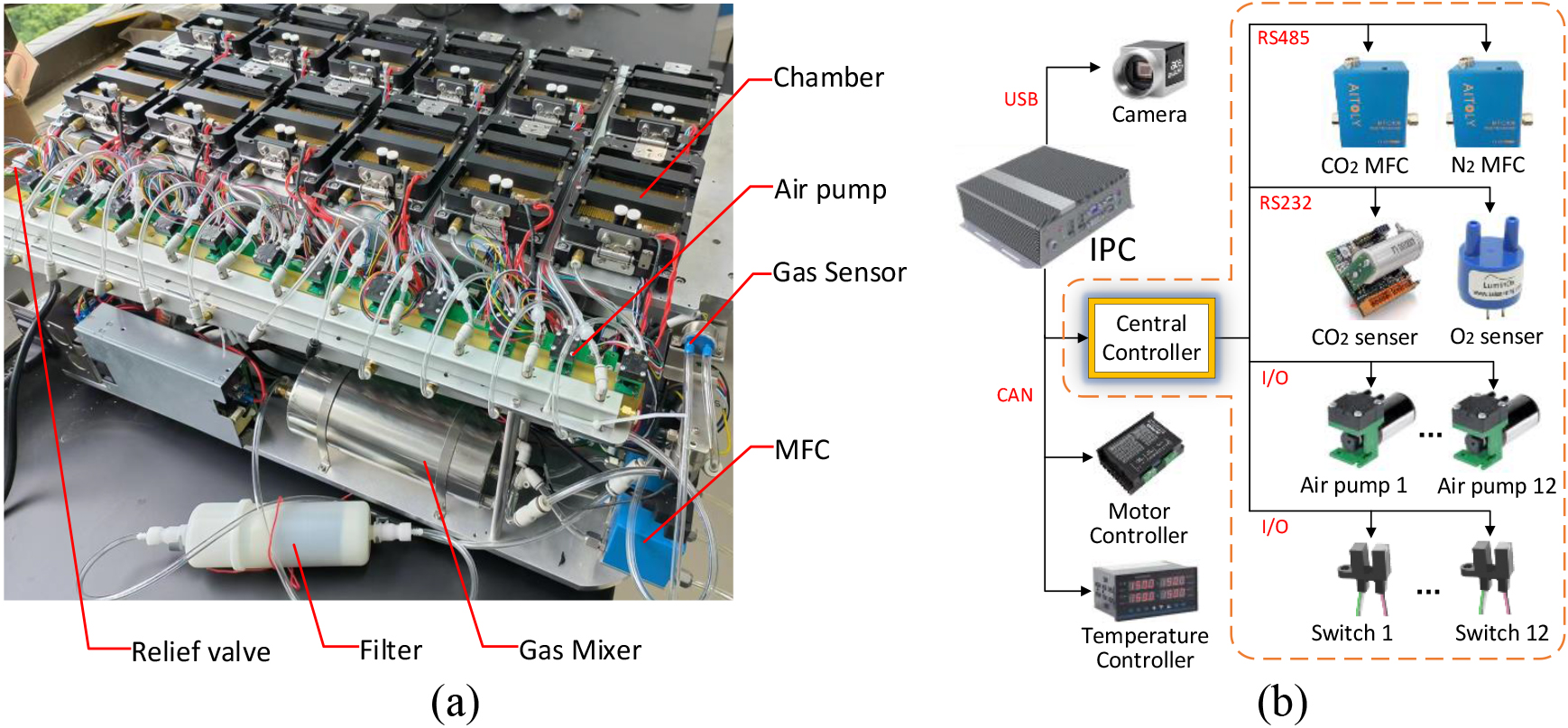
A system-based multi-chamber time-lapse embryo incubator was assembled based on the fabricated components, as shown in Fig. 3. The incubator was a compact device containing 12 chambers arranged in two rows (Fig. 3a). The gas system components were mainly installed at the rear of the incubator, including air pumps (Thomas Diaphragm pump, model 2002 VD BLDC, Monroe, USA), CO2 sensor (Novasis Innovazione Novagas2, model NG2-A-2, Italia), O2 sensor (SST Sensing LuminOx, model LOX-02-F, Coatbridge, UK), MFCs (AITOLY, model MFC300_RS485, Wuxi, China), gas mixer (Henan Xingchao Electromechanical Equipment Co., Ltd., China), relief valve (SMC, model AKH06, Japan), and filter (Hangzhou Cobetter Filtration Equipment Co., Ltd., China). The maximum flow rate of MFC for N2 and CO2 are 500 sccm and 50 sccm, respectively. The gas mixer was designed as an enclosed thin-walled cylinder, filled with three SV static mixing units and each positioned at a 90-degree angle to the adjacent units. The total volume of the gas circulation part was 2000 mL, with 950 mL for the gas mixer and 1050 mL for other components (including the chambers). The gas central controller plays a crucial role in the device, which also includes motor controllers, temperature controllers, and a camera (Fig. 3b).
The experiment of gas mixing efficiency was performed on the incubator. Firstly, the gas mixer was disconnected from the circulation part at the filter, making it open to the atmosphere. Secondly, CO2 and N2 were simultaneously introduced into the mixer at flow rates of 50 mL/min and 425 mL/min, respectively. This process lasted for more than 5 minutes to ensure that the gases were injected in a proportional ratio of 100 mL and 850 mL. It is important to note that the rest of the system was filled with air except for the mixer. Subsequently, the gas mixer was reconnected to the circulation part, and all the air pumps were activated to start operation. The concentrations of CO2 and O2 were then measured over time, expected to reach 5% and 11%, respectively, after stabilization.
In addition, to validate the performance of the proposed system and method, experiments were conducted under four initial conditions and routine operations. Instead of introducing external gas with a given concentration, an artificial offset method was used to simulate the conditions where CO2 or O2 concentration deviates from the target value.
2.4Mouse embryo assay
All animal procedures were approved by the Experimental Animal Welfare Ethics Committee of Suzhou Institute of Biomedical Engineering and Technology, Chinese Academy of Sciences. Six- to 8-week-old B6D2F1 female mice were administered 5 IU pregnant mare serum gonadotrophin (PMSG; Sigma), followed by 5 IU human chorionic gonadotrophin (hCG; Sigma) 48 h later. Females were then placed with adult B6D2F1 males of known fertility overnight and examined the following morning for vaginal plugs indicating that mating had occurred. Zygotes were collected at 21 h post-HCG in M2 (Nanjing Aibei) and denuded by a brief (less than 1 min) incubation with hyaluronidase (0.5 mg/ml, Sigma). Embryos were washed in M2 and once in the G1 (Vitrolife) culture medium, followed by random distribution of 14–16 zygotes into 50
Figure 4.
Gas concentration mesured under different flow rates. (a) Gas concentration changing over time after starting mixing. (b) Relative deviation of gas concentration to the steady state. The vertical coordinates are displayed in a logarithms scale.
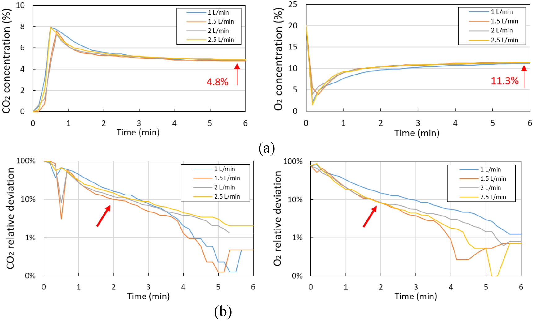
Figure 5.
Gas concentrations of CO2 and O2 and gas consumption of N2 and CO2 under the following four initial conditions: (a) CO2 is lower and O2 is higher (0% CO2 and 20% O2). (b) Both of CO2 and O2 are higher (8% CO2 and 7% O2). (c) Both of CO2 and O2 are lower (4% CO2 and 3% O2). (d) CO2 is higher and O2 is lower (8% CO2 and 3% O2). The sequence numbers of inflow at specific times are indicated by arrows and the manual interventions of chamber lids are indicated by text boxes.
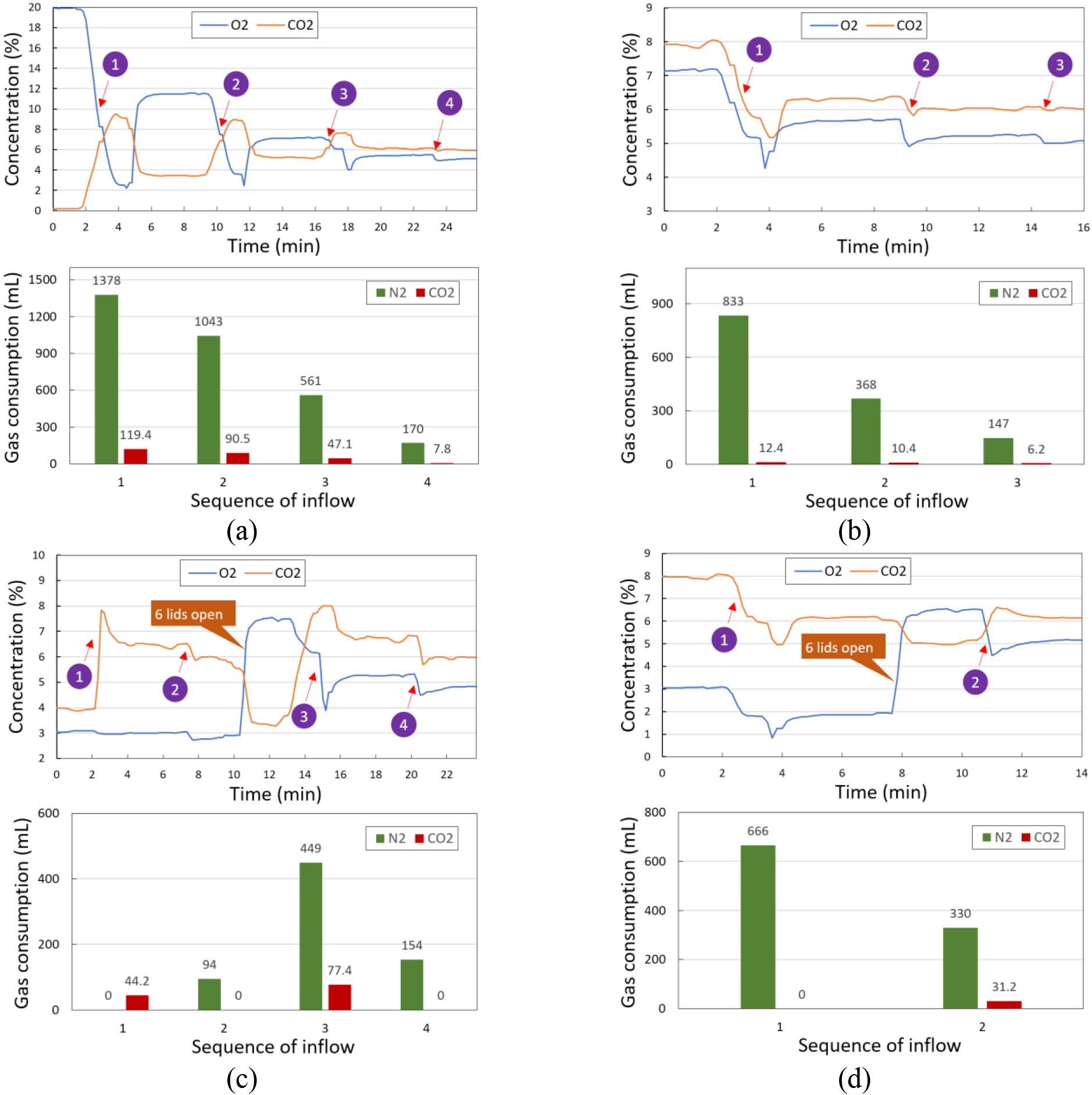
Figure 6.
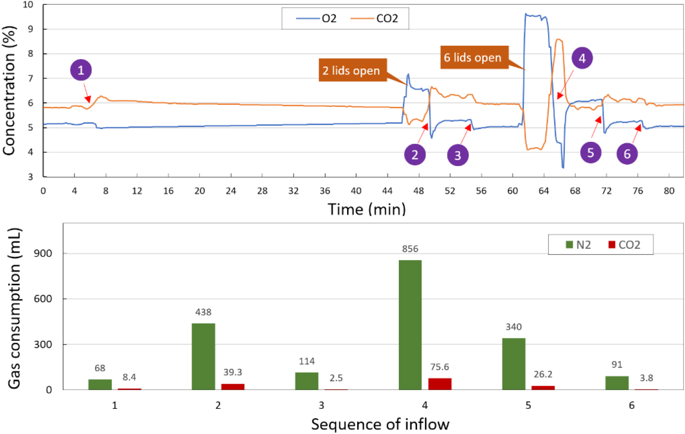
Gas concentrations of CO2 and O2 and gas consumption of N2 and CO2 under routine operations.
3.Results
3.1Gas mixing efficiency by circulation
The mixing efficiency by circulation is assessed based on the gas concentration over time. Concentration measurement is conducted under four different flow rates, ranging from 1 L/min to 2.5 L/min, with increments of 0.5 L/min. Before each test, the circulation part is filled with 100 mL of CO2 and 850 mL of N2, while the other part contains 1050 mL of air. The concentrations of CO2 and O2 are recorded simultaneously every 10 seconds from the onset to reaching stability. The test lasts for 6 minutes (Fig. 4a). The expected values for CO2 and O2 are 5% and 11%, respectively. The final concentrations reach 4.8% and 11.3%, satisfying the measurement error. The relative deviation of the two gases from the steady state values is present in Fig. 4b. The optimal mixing time and flow rate for the system are 2 minutes and 1.5 L/min as indicated by the arrows in Fig. 4b, respectively, with
3.2Gas concentration and consumption
The performance of the system was tested according to the workflow illustrated in Fig. 2, under four initial conditions that cover common application scenarios encountered in practice. Instead of introducing external gases with specific concentrations, artificial offsets were applied by the software to generate the initial deviations, except for air. The target gas concentrations were set to 6% for CO2 and 5% for O2, the best parameters for embryo development, based on which the artificial offsets were implemented at the beginning. The initial concentration combinations of the two gases are as follows: 0% CO2 and 20% O2, 8% CO2 and 7% O2, 4% CO2 and 3% O2, and 8% CO2 and 3% O2. These initial concentrations have been stabilized in preparation for subsequent testing. In addition, the acceptable absolute deviation from the target values is defined
Figure 5a and b show that under the two initial conditions (0% CO2 and 20% O2, 8% CO2 and 7% O2), the concentrations of CO2 and O2 both stabilize in an acceptable range of
When the gas concentration exceeds the acceptable range, the single adjustment time of the system is determined by the gas inflow volume, which equals the gas consumption (Fig. 5). Once all lids are closed and gas stabilization is achieved, the recovery time will not exceed 5 minutes after a new deviation occurs (Fig. 6).
In the scenario where the system is initially filled with air (0% CO2 and 20% O2), the gas consumption is significantly higher than the other three conditions, with a total volume of 3152 mL for N2 and 263.8 mL for CO2 (Fig. 5a). After stabilization, the gas system adjusts every 40 minutes with a typical consumption of 68 mL for N2 and 8.4 mL for CO2 (Fig. 6). Opening and closing two lids after stabilization, a consumption of 552 mL for N2 and 41.8 mL for CO2 is needed. Also, opening and closing six lids after stabilization, a consumption of 1287 mL for N2 and 105.6 mL for CO2 is needed. Consequently, in routine operations with five lids open per day, each time with six lids, the theoretical average gas consumption of N2 and CO2 per day can be calculated using the following formulas respectively: (24 h
3.3Mouse embryo development
Table 1
Mouse embryo development results after 96 hours of culture
| Chamber | 1 | 2 | 3 | 4 | 5 | 6 |
| No. of embryos | 15 | 16 | 15 | 15 | 16 | 14 |
| No. of blastocysts | 14 | 16 | 15 | 14 | 15 | 14 |
| Blastocyst rate | 93.3% | 100% | 100% | 93.3% | 93.7% | 100% |
| Chamber | 7 | 8 | 9 | 10 | 11 | 12 |
| No. of embryos | 15 | 16 | 14 | 15 | 14 | 15 |
| No. of blastocysts | 14 | 15 | 13 | 15 | 14 | 14 |
| Blastocyst rate | 93.3% | 93.7% | 92.8% | 100% | 100% | 93.3% |
Figure 7.
Morphology of mouse embryos cultured for 96 hours from zygotes in chamber 3 (a) and chamber 11 (b) of the incubator.
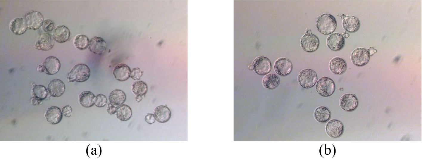
To evaluate the effect of the system-based incubator on embryo development, we performed a thorough mouse embryo assay that encompassed all chambers. The morphology of mouse embryos cultured from zygotes for 96 hours is illustrated in Fig. 7, and the corresponding statistical data is presented in Table 1. After 96 hours of culture, the percentage of mouse embryos reaching the blastocyst stage exceeded 90% in all chambers, with some reaching 100%. The results provide compelling evidence that the gas environment established in the incubator plays a crucial role in facilitating the successful development of embryos.
4.Discussion
Compared to the existing incubators, our system has 12 miniature air pumps for gas mixing and distribution, rather than a single air pump. This enables independent control of gas in each chamber, ensuring that others still normally receive the gas supply when some chamber lids are opened. Moreover, this design ensures that the mixing gas is evenly distributed to each chamber and is not affected by the flow resistance differences between channels. Thus, our system promotes the establishment of a highly uniform gas concentration throughout the entire zone.
For the determination of mixing parameters, shorter mixing times and lower flow rates are two key design criteria. A shorter mixing time allows for faster system recovery, which enables rapid correction of gas concentrations when deviations occur. Air pump with a lower gas flow rate helps to reduce vibration and noise and minimize disturbance to the cells. A lower flow rate guarantees less cold gas into the chambers per unit time, minimizing the effect on the temperature distribution inside the chambers. In our system, both CO2 and O2 concentrations take 6 minutes to stabilize under different flow rates (Fig. 4a), which may be a little long for practical applications. Considering a relative deviation of
To achieve stable gas concentration, multiple adjustments are required rather than just one, which can be attributed to two main reasons. First, in some cases, the inflow volume exceeds the interior volume of the mixer, causing a portion of the new gas to leak out through the relief valve as well. Second, the mixing time of two minutes determined to ensure a relative deviation of less than
Sealing is a critical factor in ensuring the proper functioning of the gas system. In this regard, the chambers have a greater impact than the pipes, as their quality control procedures are more difficult than the latter. The air pump will operate at a low flow rate when the gas concentration is within an acceptable range. Meanwhile, the air could be gradually introduced to the gas system due to the negative pressure in the chambers. Poor sealing leads to an amount of air entering the system, resulting in longer adjustment time and even failure to reach the target value. Therefore, better sealing helps to maintain longer stability. In addition, introducing an appropriate amount of air is beneficial so that fresh gases of CO2 and N2 can be supplied during adjustments when gas concentrations deviate.
The blastocyst rate is a crucial indicator for evaluating the culture environment in mouse embryo assays. A blastocyst rate higher than 80% is generally considered acceptable. The results reveal that the blastocyst rate in all chambers exceeds 90%, with some reaching 100% (Table 1). It suggests that the device’s condition is suitable for the development of mammalian embryos. However, it is important to note that the development of mouse embryos and human embryos may not be identical. Therefore, this data cannot directly reflect the culture effect on human embryos. Nonetheless, the result still provides valuable reference for studying human embryonic development and clinical applications. Further validation through clinical trials is necessary for our device.
5.Conclusion
In this study, we propose a novel system and method to address the shortcomings of the gas system in existing embryo incubators. By investigating the gas mixing and distribution process, theoretical calculation of the inflow volume of supply gases, and determination of mixing parameters, we realized an embryo incubator with the characteristics of high accuracy, fast recovery, and low gas consumption. Additionally, a mouse embryo assay was performed in the incubator to demonstrate the successful development of mouse embryos from zygote to blastocyst stage. Our method offers a superior alternative gas system for multi-chamber incubators, especially for low gas consumption. Future improvements will focus on enhancing the mixing efficiency and preheating the gas before entering the chamber. Given the universality of the method, we anticipate its potential expansion into other applications beyond life science, such as in the industrial and energy sectors.
Acknowledgments
This work was supported by the National Key R&D Program of China (Grant Nos. 2022YFA1104800, 2023YFC2415000), the Strategic Priority Research Program of the Chinese Academy of Sciences (Grant No. XDA16020704), and the Key Research and Development Program of Jiangsu Province (Grant No. BE2023721).
Conflict of interest
The authors declare no conflict of interest.
Ethical statement
All animal procedures were approved by the Experimental Animal Welfare Ethics Committee of Suzhou Institute of Biomedical Engineering and Technology, Chinese Academy of Sciences.
References
[1] | Swain JE. Optimal human embryo culture. Seminars in reproductive medicine. (2015) ; 103-117. |
[2] | Tse HM, Gardner G, Dominguez-Bendala J, et al. The Importance of Proper Oxygenation in 3D Culture. Frontiers in Bioengineering and Biotechnology. (2021) ; 9. doi: 10.3389/fbioe.2021.634403. |
[3] | Buyalos R, Li M, Miller F, et al. The effect of media type, gas environment, and incubator model on IVF success rates. Fertility and Sterility. (2008) ; 89: : S17-S18. doi: 10.1016/j.fertnstert.2008.02.054. |
[4] | Li RZ, Luo YZ, Xu JT, et al. Effects of oxygen concentrations on developmental competence and transcriptomic profile of yak oocytes. Zygote. (2020) ; 28: (6): 459-469. doi: 10.1017/s0967199420000337. |
[5] | He HH, Zhang HZ, Li Q, et al. Low oxygen concentrations improve yak oocyte maturation and enhance the developmental competence of preimplantation embryos. Theriogenology. (2020) ; 156: : 46-58. doi: 10.1016/j.theriogenology.2020.06.022. |
[6] | Cohen J, Rieger D, Mastenbroek S, et al. ‘There is only one thing that is truly important in an IVF laboratory: Everything’ Cairo Consensus Guidelines on IVF Culture Conditions. Reproductive Biomedicine Online. (2020) ; 40: (1): 33-60. doi: 10.1016/j.rbmo.2019.10.003. |
[7] | Lee M, Grazi R, Seifer D. Incorporation of the Cook K-Minc incubator and media system into the IVF lab: The future of IVF. The Journal of Clinical Embryology. (2010) . |
[8] | Swain JE. Decisions for the IVF laboratory: Comparative analysis of embryo culture incubators. Reproductive Biomedicine Online. (2014) ; 28: (5): 535-547. doi: 10.1016/j.rbmo.2014.01.004. |
[9] | Smith GD, Monteiro Da Rocha A. Advances in embryo culture systems. Semin Reprod Med. (2012) ; 30: (3): 214-21. doi: 10.1055/s-0032-1311523. |
[10] | Aparicio-Ruiz B, Romany L, Meseguer M. Selection of preimplantation embryos using time-lapse microscopy in in vitro fertilization: State of the technology and future directions. Birth Defects Research. (2018) ; 110: (8): 648-653. doi: 10.1002/bdr2.1226. |
[11] | Bosch EP, Bori L, Beltran A, et al. Artificial intelligence system for the automation of the blastocyst morphology evaluation in GERI Time-lapse Incubator. Human Reproduction. (2021) ; 36: : 200-200. |
[12] | Meyers S, Burruel V, Kato M, et al. Equine non-invasive time-lapse imaging and blastocyst development. Reproduction Fertility and Development. (2019) ; 31: (12): 1874-1884. doi: 10.1071/rd19260. |
[13] | Bose S, Biswas S, Saha S, et al. Control system for a four-component gas mixing unit. Nuclear Instruments and Methods in Physics Research Section A Accelerators Spectrometers Detectors and Associated Equipment. (2009) ; 602: (3): 839-841. |
[14] | Tilman, Sauerwald, Nikolai, et al. Gas mixing apparatus for automated gas sensor characterization. Measurement Science & Technology. (2014) . doi: 10.4236/aces.2019.91002. |
[15] | Thakur RK, Vial C, Nigam KDP, et al. Static mixers in the process industries – A review. Chemical Engineering Research & Design. (2003) ; 81: (A7): 787-826. doi: 10.1205/026387603322302968. |
[16] | Zhuang Z, Yan J, Sun C, et al. The numerical simulation of a new double swirl static mixer for gas reactants mixing. Chinese Journal of Chemical Engineering. (2020) ; 28: (09): 2438-2446. |
[17] | Haddadi MM, Hosseini SH, Rashtchian D, et al. Comparative analysis of different static mixers performance by CFD technique: An innovative mixer. Chinese Journal of Chemical Engineering. (2020) ; 28: (3): 672-684. doi: 10.1016/j.cjche.2019.09.004. |
[18] | Hirschberg S, Koubek R, Moser F, et al. An improvement of the Sulzer SMX (TM) static mixer significantly reducing the pressure drop. Chemical Engineering Research & Design. (2009) ; 87: (4A): 524-532. doi: 10.1016/j.cherd.2008.12.021. |
[19] | Wang HX, Wang RY, Liu JR. Decreased in vitro fertilization and cleavage rates after an equipment error during CO2 calibration. Fertility and Sterility. (2000) ; 73: (6): 1247-1249. doi: 10.1016/S0015-0282(00)00537-9. |


