
Quantitative assessment of the level of instability of a single-plane balance platform
Abstract
BACKGROUND:
Balance training on unstable surfaces is widely used in medicine and sports. The main disadvantage of balance platforms is weakly definable assessment of the level of instability (IL) they create.
OBJECTIVE:
To evaluate the mechanical characteristics of a suspended single-plane instability balance platform which determines quantitative instability characteristics.
METHODS:
Three criteria influencing the IL were evaluated: 1. The displacement of the platform board by changing the position of the object on the board; 2. Amount of force required for board displacement; 3. The vibration damping of the platform.
RESULTS:
1. 1IL the displacement of the object on the board affected 0.66 cm. the displacement of the board relative to the platform frame; 2IL – 0.79 cm; 3IL – 0.91 cm.; 2. A force of 2.64 is required for a board displacement of 1IL compared to 2IL and 5.76 times that of 3IL. 3. Damping factor 1IL – 0.015, 2IL – 0.006, 3IL – 0.003.
CONCLUSIONS:
1. The longer the suspension, the change in the position of the object on the board affects the greater movement of the board relative to the platform. 2. Different IL can be compared with each other depending on how different the force required to cause the board to move. 3. The platform dampens vibrations weakly, but the damping between 1 and 3 IL differs about 5 times.
1.Introduction
1.1Principles of maintaining postural control
Human postural control is a feature of the body dedicated to maintaining the center of mass (COM) lines of gravity within the base of support (BOS) with minimal sway. Postural control can be classified in different ways. It is usually divided into static and dynamic. Static stability is when the balance is not disturbed by external forces, e.g. quiet, standing. Dynamic stability is defined as maintaining or restoring balance in response to internal or external disturbances [1]. Assessing postural stability from a neuromechanical perspective, equilibrium is an ongoing process in which the COM of the body is actively returned to the boundaries of the support area [2]. The human body is largely unstable due to gravity and additional destabilizing forces resulting from body movement and the body’s interactions with an environment [3]. The maintenance of postural control is based on two fundamental processes: 1) feedback, 2) primary control. Postural response of the feedback is used when postural stability is unexpectedly disturbed. An example of this could be slipping on ice. Sensory feedback acting through the nervous system plays an important role in this process.
The process of feedforward postural control is used to restore a predetermined loss of postural stability. This postural response is performed even before potentially destabilizing voluntary movement, and aims to maintain stability during the movement.
Balance in the anterior-posterior (A-P) direction is largely based on the ankle joint strategy, while in the medio-lateral (M-L) direction, movements are controlled by abductive and adductive movements of the hips [4, 5]. The ankle strategy is used to eliminate minor disturbances, usually on a hard surface. To implement this strategy, the muscles of the distal areas of the legs are activated. Fluctuation occurs through the ankle, while the hips and knees are relatively tense. For example, during forward sway, paravertebral, hamstring and gastrocnemius muscles are activated to keep the COM within the support area. Abductor, quadricep, and tibial muscles are deactivated at the same time [6]. The hip strategy can be described as a movement pattern designed to correct an imbalance by creating torsion through the hip joints. When the balance is disturbed by pushing or pulling, the flexion/extension muscles of the thigh are activated together with the flexion/extension muscles of the torso to maintain balance, only in different patterns. This depends on the way in which the balance has been disturbed. Activation of both hip and torso muscles are related to hip strategy and are important for maintaining balance on the frontal axis [6]. If the movement of the COM relative to the body support area exceeds the ability to restore the ratio of COM to Base of Support (BOS) required to maintain postural stability, then a stepping response is activated to ensure postural stability. In order to restore disturbed stability, a mechanism of postural synergy is used, which is continuously active through continuous sensory feedback, thus constantly regulating (adjusting and correcting) postural stability [7].
To date, there is not a sufficiently well-known balance disruption method that can best summarize the mechanism of imbalance most commonly found in everyday life [3]. Standing on an unstable platform constantly disturbs the balance of the body due to the changing position of the support base. Incorrect and irregular COM movement makes it necessary to ensure COM support within the BOS, which requires constant neural integration. The body’s efforts to control platform movement can reduce the effects of anticipated imbalances, thus limiting platform movements. To maintain balance control, the central nervous system is involved more when standing on an unstable platform than when standing still. Sensory information from the visual and vestibular systems is important when standing on an unstable platform. Continuous head movements and mismatches of sensory information entering the brain (from different sensory sources or sensory organs) can make standing even more difficult. Therefore, the role of proprioceptive feedback when standing on an unstable platform is very important.
From a biomechanical perspective, it has not yet been analysed in detail which mechanisms of postural stability are dominant when standing on an unstable platform. Critically assessing, the level of imbalance created by these platforms should be high due to the dynamically changing body mass center and support area [8].
1.2Forms of postural instability
Unstable platforms are most often used for balance training workouts. These workouts are a widely used tool in various medical fields e.g. in rehabilitation or geriatrics. Balance workouts include exercises performed on unstable or moving surfaces. According to the balancing mechanisms, these exercises can be divided into conventional training systems (CTS) and reactive balance training (RBT) (Fig. 1).
Figure 1.
A – conventional training system; B – reactive balance training.
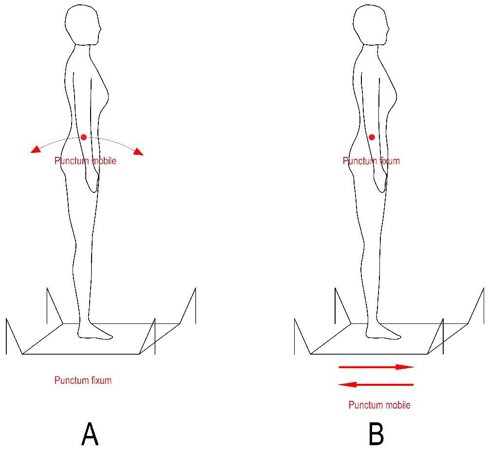
They differ in that those different approaches are used to disrupt stability, as well as activating different strategies to balance. In the case of RBT, the balance is disturbed both by changing gravity vectors (resulting from the movement of the center of mass of the body) and by the displacement of the body support relative to the center of mass of the body. In the case of CTS, it can be described using an inverted pendulum model. During it, the body’s center of mass moves at a stable BOS position. In order to maintain the vertical position of the body, the gravity vector of the latter is controlled using torques caused by the ankle joint. According to current data, RBT training is suitable for training in anticipatory balance control [9].
1.3Types of unstable platforms
According to the mechanical constructions, 2 most common commercially available categories of unstable platforms can be distinguished: 1. Suspended single-plane instability balance platform (SIPIBP); 2. Supporting instability balance platform. In this work, we will focus on SIPIBP. Posturomed, Abilli, Shuttle Balance Senior platforms can be included in this category. The general principle of operation of these platforms is based on the creation of an unstable base by hanging it freely. The principles of hanging are different.
Posturomed© platform is 60 cm
Shuttle Balance Senior© platform. The platform board is hung to the frame using non-depreciating chains. By adjusting the length of the chains, the height of the platform board and the tilt angle are changed. The stability of the platform is adjusted by selecting the chain anchorages on the board: the closer the chain anchorages are to the center of the board, the higher the level of instability (LI). The device also uses elastic dampeners to adjust lateral resistance, and control cords to adjust range of motion.
Table 1
Definition of IL by chain lengths and clamp heights
| Level of instability | Holder length (m) | Perpendicular distance between the board and the attachment to the support column (m) |
|---|---|---|
| 3 | 0.445 | 0.435 |
| 2 | 0.255 | 0.240 |
| 1 | 0.125 | 0.115 |
The advantage of the support platforms used is that they have defined LI measurements for the support area tilt angles used, such as Biodex Balance© or NeuroCom EquiTest System©. However, these platforms are mainly adapted for conventional training and balance assessment, where the ability to maintain a center of gravity at the axial center of equilibrium is provided by the platform, which coincides with the support area. This means that this method of balancing relies mainly on ankle joint movements, while other balancing strategies are not sufficiently activated. With the popularity of reactive balance training, SIPIBP is becoming increasingly relevant. The main disadvantage of these platforms, which are still in use, is that they do not have a developed LI assessment. For example, stabilization time is used for the quantitative dynamic stability assessment of Posturomed©, but measured time in the presence of differently tightened elastic elements can vary drastically, even for the same subject. Unable to quantify the LI, the following problems are encountered:
1. In the absence of a measured LI value, it is difficult to assess the postural stabilities of different groups of people.
2. In the absence of a unified LI measurement, it is difficult to assess the effectiveness of the applied training and the rehabilitation process.
3. According to the known LI quantitative definitions and measured values of human postural stability, the most appropriate and safest training programs could be selected.
The aim of this work is to evaluate the mechanical characteristics of SIPIBP that are important for quantitative instability characteristics.
2.Method
2.1Platform construction
An Abili Balance© (Kaunas, Lithuania) device was used for the study. It consists of a frame, columns attached to it, and a board (size 0.6
Figure 2.
Suspended single-plane instability balance platform construction.
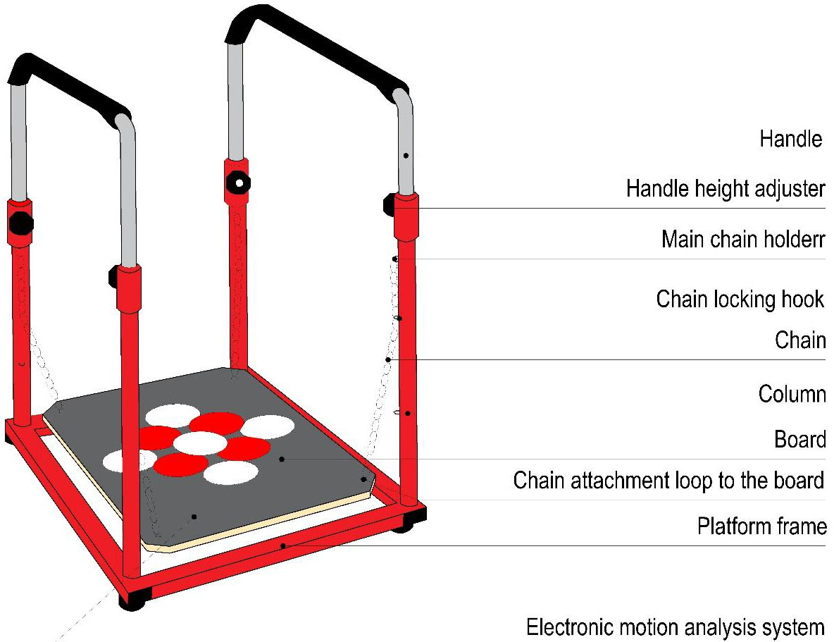
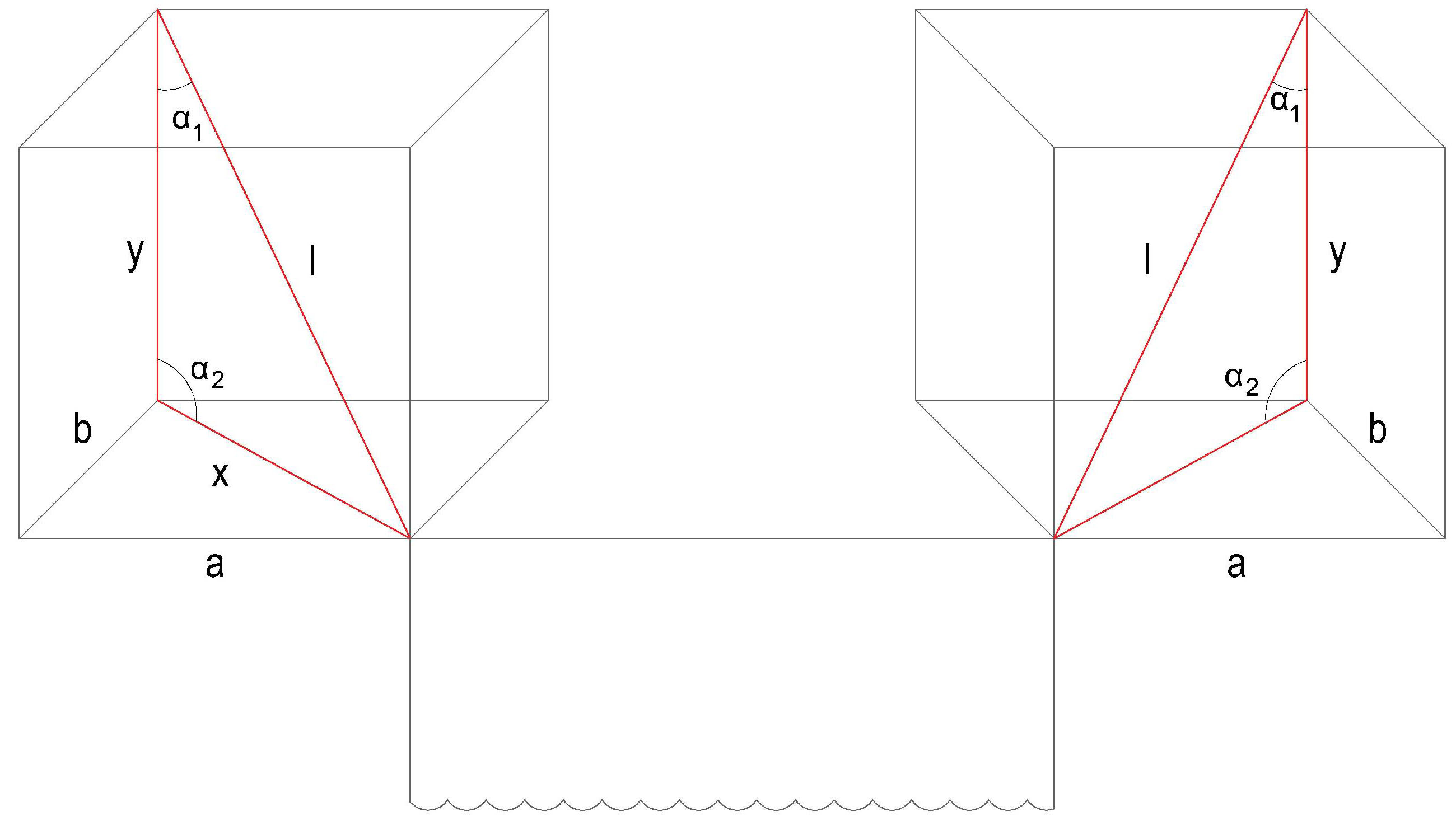
Figure 3.
Spatial schematic representation of the board hanging.
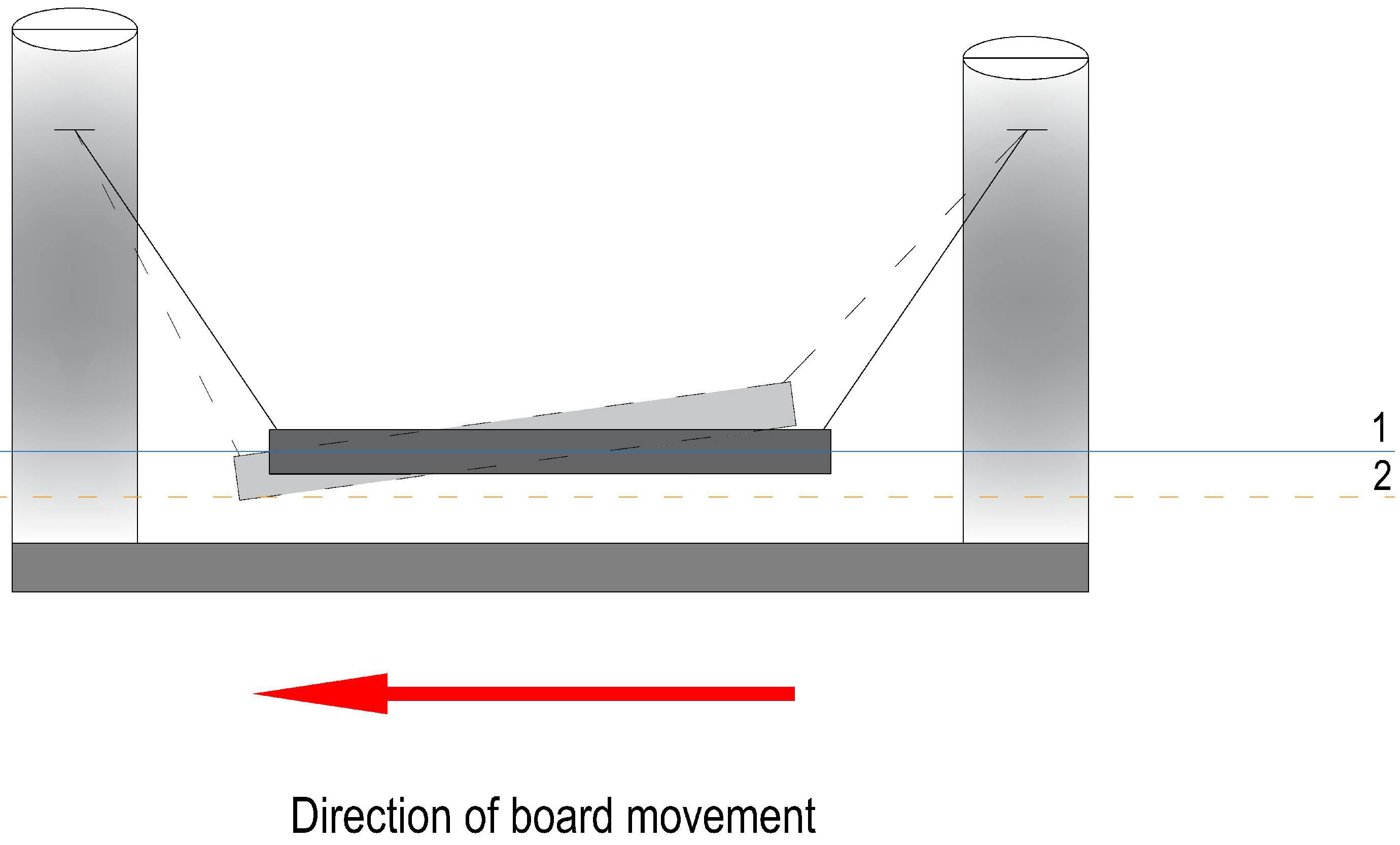
2.2Platform movement mechanics
The board held by the platform frame can move in 3 main directions: anterior-posterior, medio-lateral, and oblique (Fig. 4). As the board moves, the size of the angles between the column and the chains changes. The change in these angles depend on the direction in which the board is moving. If the board approaches the platform frame, then the angle of the column-chain on that side decreases. Therefore, the approaching edge of the board descends below the height of the neutral board position. The opposite situation occurs with the edge of the board moving away from the frame: the angle of the platform frame column-chain from which the board moves increases, so the edge moving away from the frame rises above the height of the neutral board position (Fig. 5). Similarly, the movement takes place as the board moves sideways.
Figure 4.
The main directions of movement of the balance platform board.
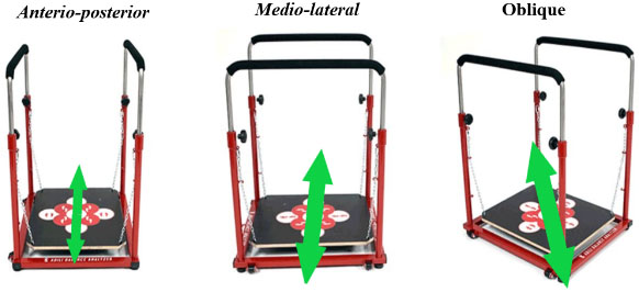
Figure 5.
The solid line shows the position of the platform at equilibrium. The dotted line shows the movement of the platform in the A-P directions and the formation of the slope of the plane. Solid line no. 1 shows the height of the board in the neutral position. Dotted line no. 2 shows the height of the board end approaching the frame (below the former neutral position).
2.3Principles of platform board movement
Different SIPIBPs create imbalances in different ways. When standing on the balance platform, the initial neutral position is when the vector of the center of mass of the body is projected into the position of the center of the board (A) and the platform frame (B) (Fig. 6). The displacement of the platform board results from two different principles:
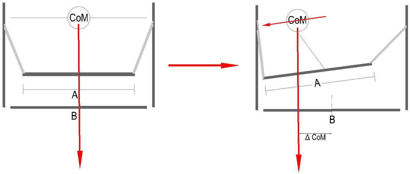
1. Due to the changing position of the center of body mass. When the position of the center of mass changes in respect to the centers of the platform frame and the board, the force of gravity is redistributed between the supports (suspensions). A higher load falls on this suspension, to which the center of mass is closer. As the holders are flexible, a displacement of the board occurs, coinciding with the direction of movement of the center of mass of the body (Fig. 7).
Figure 6.
Neutral position when standing on a balance platform when COM coincides with BOS.
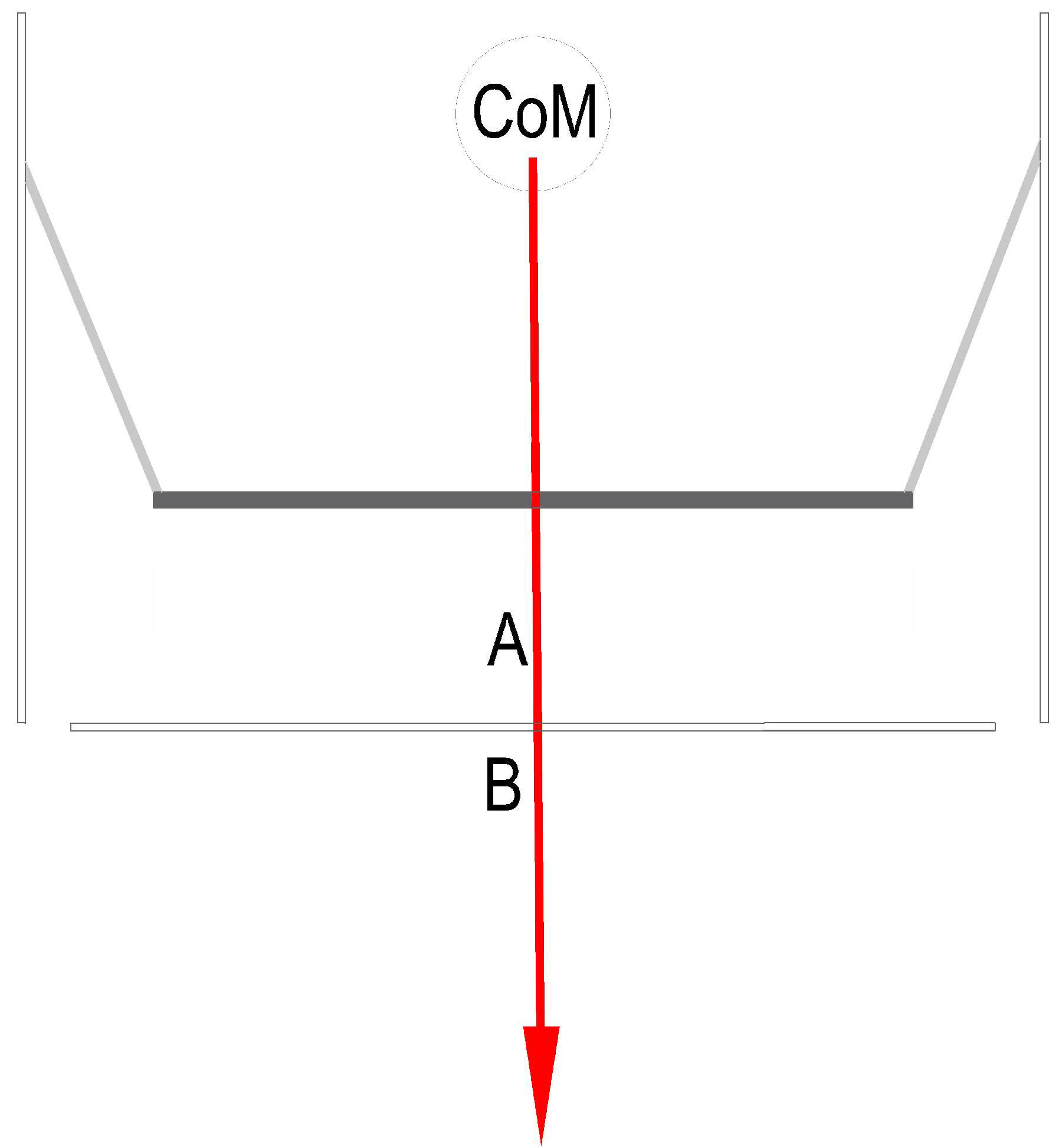
Figure 7.
Changes in the center of mass of the body are caused by the movement of the board, when the change in the position of the center of mass affects the displacement of the board and the mismatch between COM and BOS.
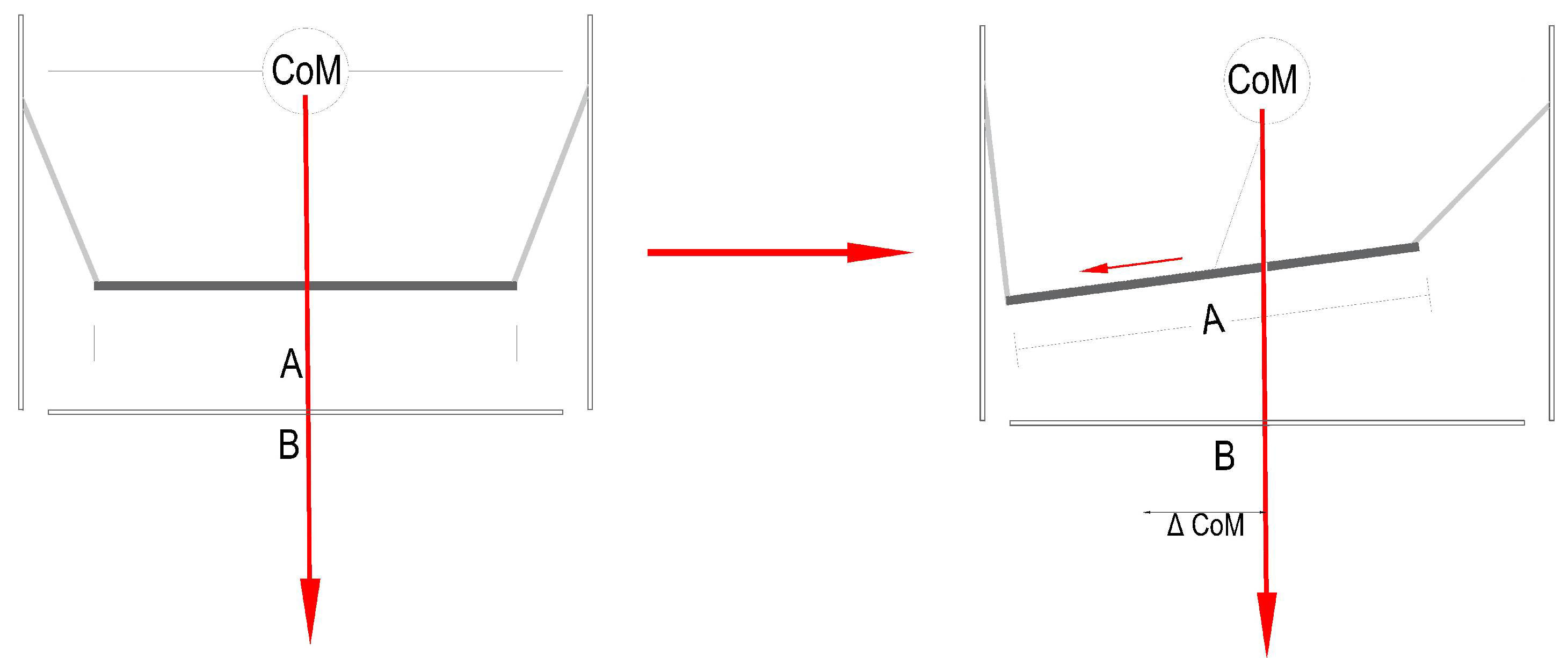
2. With a stable position of the center of mass of the body. In this case, the position of the center of gravity with respect to the center of the platform frame is fixed. From a biomechanical perspective, this movement of the board is most dependent on the movements caused by the lower part of the body (Fig. 8).
Figure 8.
The movement of the board in a stable position of the center of mass of the body is caused by the movements of the lower extremities.
Such a dual-influenced movement of the board – in one case with a stable center of gravity, and in another case due to the movement of the center of gravity itself – creates a mixed mechanism of equilibrium perturbation. In hypothetical circumstances, when a person is standing on a platform, the balance is disturbed in both of these ways, and a dynamic alignment of the center of mass and the support area is required to restore and maintain balance. It is likely that LI quantification requires an integrated approach to platform design, and quantification of each of the equilibrium perturbation mechanisms.
2.4Platform movement assessment
3 types of tests were performed to quantify the LI of the hanging reactive balance platform:
1. Evaluation of the relationship between the changing position of the center of gravity center and the motion of the balance platform board. Measurement of board displacement caused by change in the position of the center of mass of the body. In order to assess how the body’s center of mass movements influence the displacement of the board, a simplified pattern of the center of mass of the body’s movement was created. During it, two sliding rails were attached to the balance platform board. A weight was placed on the rails in the center of the board. On the rails, this weight was pushed every 1 cm interval from the center to the edge of the board. After each weight displacement, the displacement of the center of the board relative to the platform frame was also measured. Measurements were performed for each LI separately. Measurements in the front-rear (A-P) direction were performed. The positions of the balance platform board and frame were set to a neutral horizontal position before the measurements. The board is loaded using the weights of 20 kg (dimensions 0.24
Figure 9.
Test scheme 1. A – the initial weight position is marked; B – weight position, after its displacement on the rails; x – the distance by which the weight was moved (with respect to the center of the board); y is the offset of the center of the board (O1) in relation to the platform frame (O2) after the move of the weight A to the position B at a distance x.
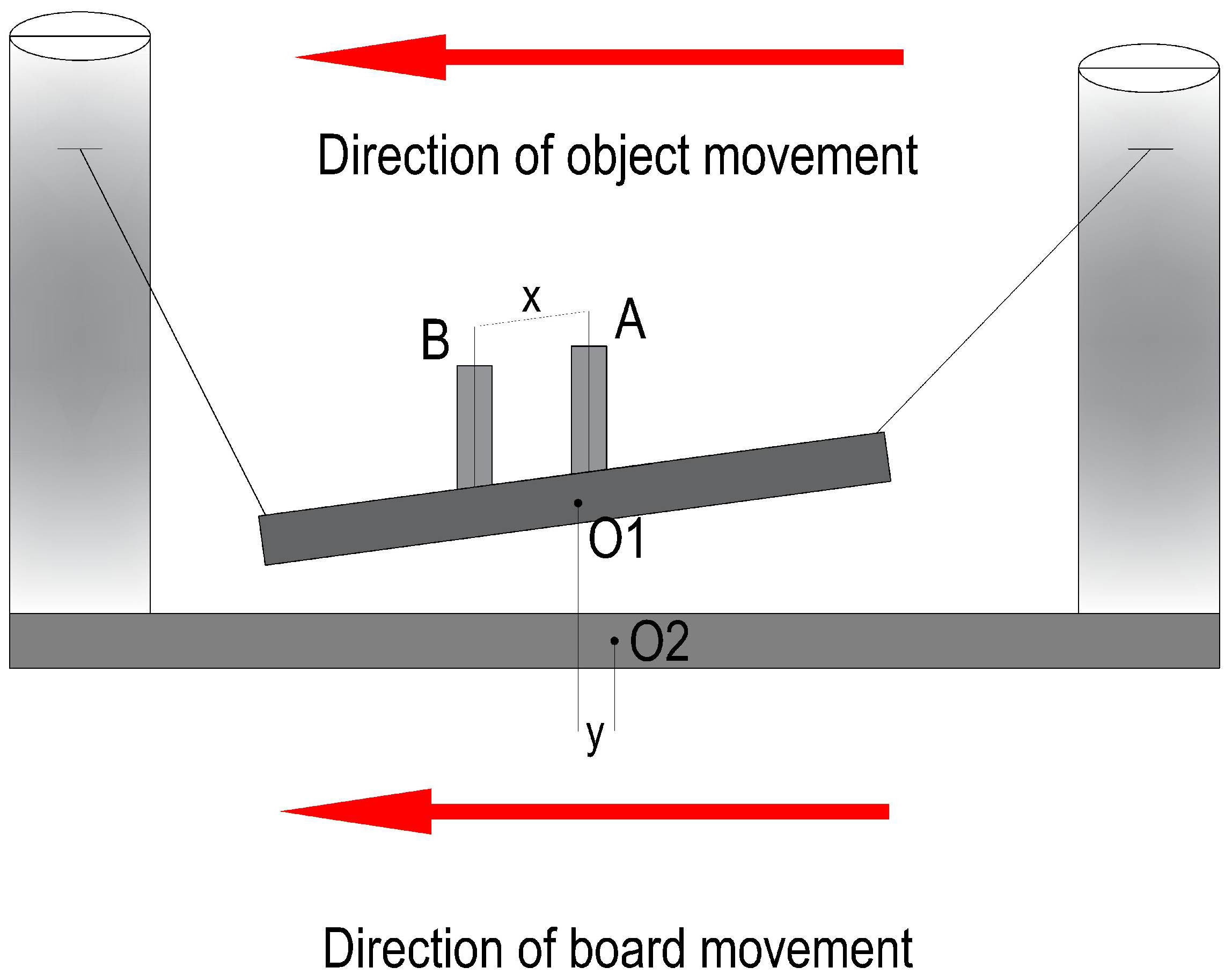
Figure 10.
Test scheme 2. 1 – additional frame, 2 – power meter, 3 – inelastic cable.
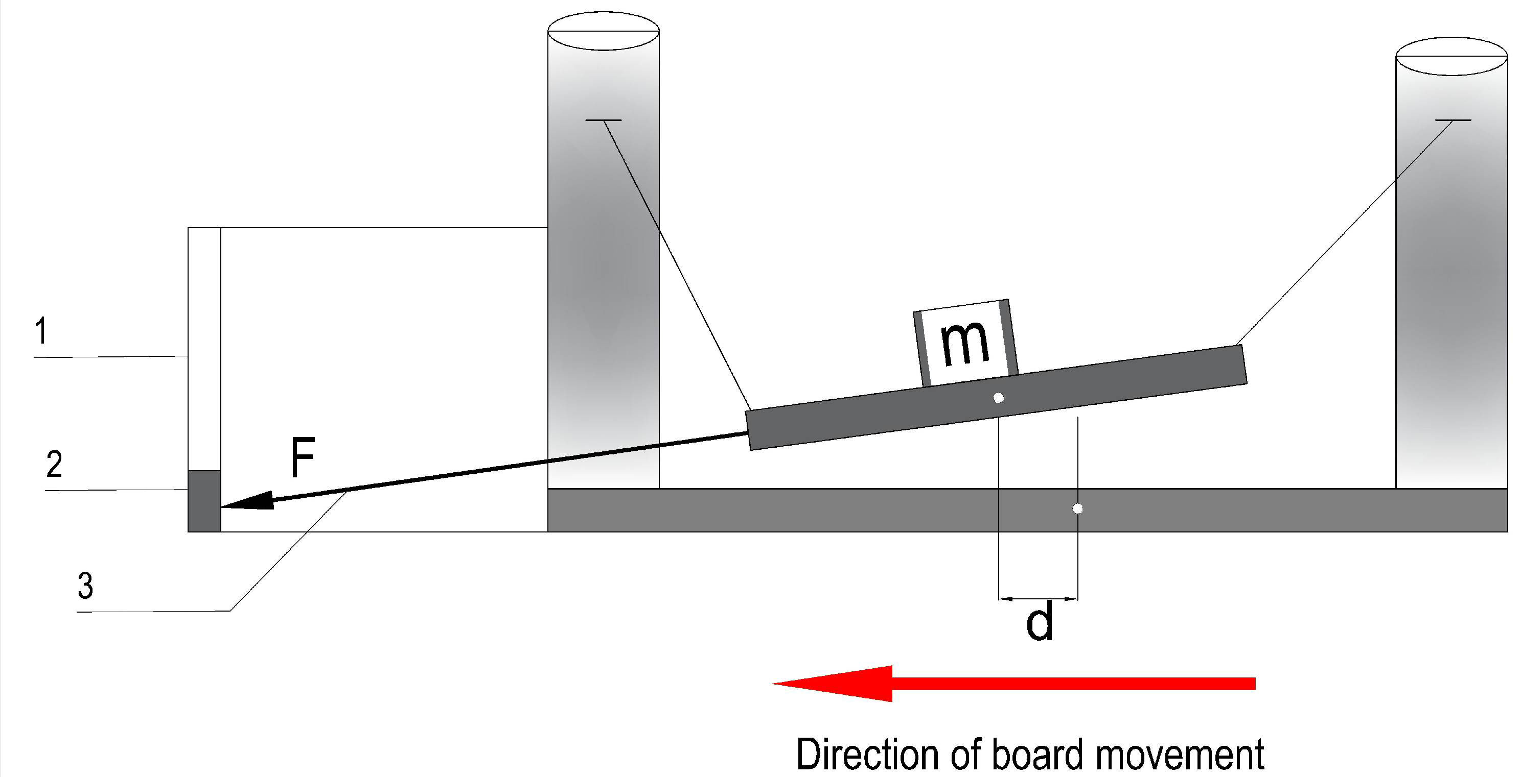
2. Evaluation of the movement of the balance platform board at a stable position of the center of gravity. The load on the board of the same weight and dimensions as in test 1 was used during the test. The weights are placed in the center of the board. An extra frame was constructed in addition to the platform. A sliding rail with a digital force transducer (RS232, Mecmesin, measuring range 10 N – 2500 N, accuracy range
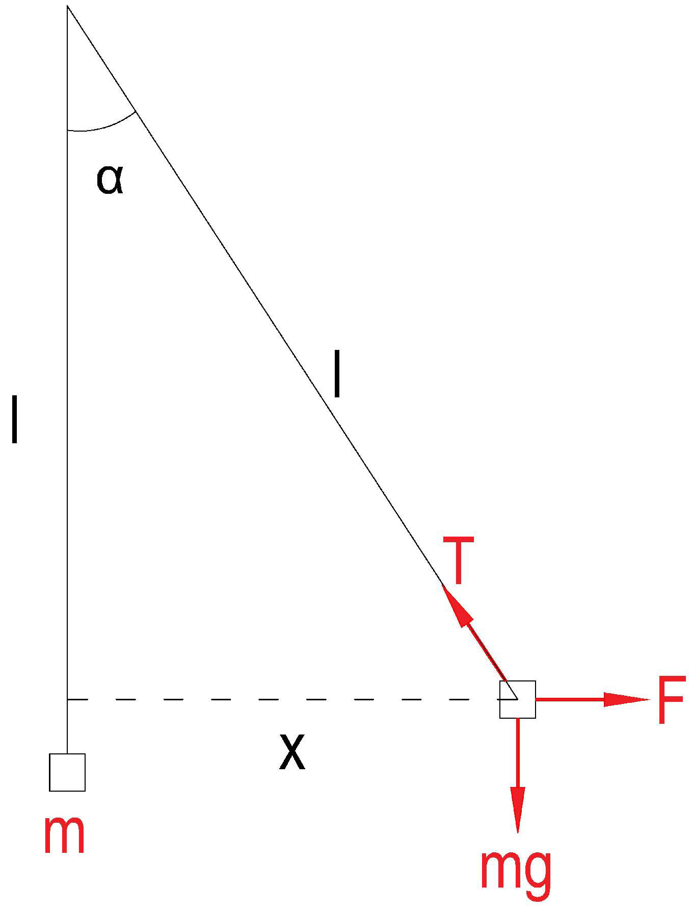
(1)
Figure 11.
Parameters affecting LI.
3. In order to evaluate how the platform dampens vibrations, the damping factor was measured. In each of the LI, the board was pulled back from the neutral position and released for oscillation. The conditions for each LI test are given in Table 2. In the case of LI 3 and 2, the distance at which the edge of the board approaches the contour of the platform frame is retracted. In the 1
(2)
Table 2
Experimental conditions, in each of the IL
IL Holder length (m) Offset of the board center relative to the center of the platform frame (distance at which the board was retracted) (cm) The force required to keep the board in a stable retracted position before the fluctuations began (N) Duration of measurement (s) 3 0.445 4.8 132 60 2 0.255 4.8 196 60 1 0.125 1.6 310 60 Therefrom, the system motion Eq. (3) is written:
(3)
The period of the system pendulum can be calculated according to the following Eq. (4):
(4)
In practice, the period is calculated from the obtained vibrograms. The actual system frequency is calculated (
(5)
The critical damping constant (
(6)
The damping factor (
(7)
Damping coefficient (
(8)
3.Results
Results of the evaluation of the positions of the changing body mass center and balance platform board motion correlation.
In the event of a displacement of the center of mass in relation to the center of the board, there is also a displacement of the board relative to the platform frame. At different LIs, the latter shift is different. The higher the LI, i.e. the longer the support chains, the greater the displacement of the center of the board relative to the frame (Fig. 12). After moving the center of gravity to the final position of the board, the maximum displacements of the board, influenced by the movement of the center of gravity in different LIs, were measured (Fig. 13). Through assessing the value of the load displacement with respect to the board, and the displacement of the board center within the normal human mass range, no significant change is observed (Table 3).
Table 3
Relationship between board center displacement and board load (center of mass position 15 cm. from center, 3 IL)
| Board load (kg) | Board center displacement (cm) |
|---|---|
| 20 | 0.5981 |
| 30 | 0.5981 |
| 40 | 0.5980 |
| 50 | 0.5982 |
| 60 | 0.5981 |
| 70 | 0.5980 |
Figure 12.
The change in the position of the center of mass is influenced by the displacement of the board at different ILs with 40 kg load.
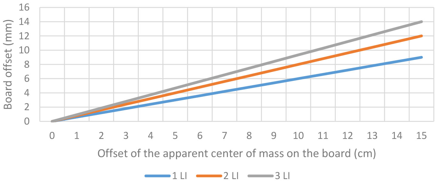
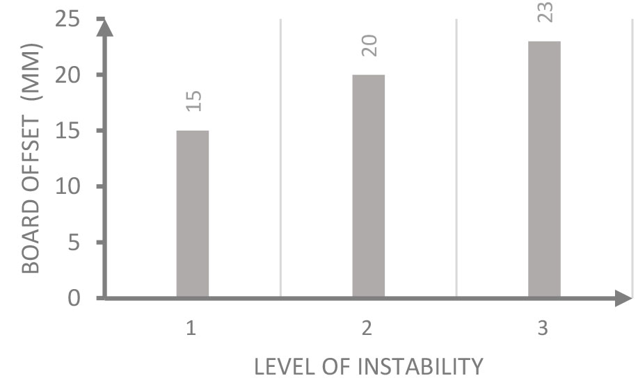
Figure 13.
Maximum displacement of the board, in each of the IL, with the center of mass of the body displaced to the rear position of the board (25 cm from the center, 40 kg load).
Results of the evaluation of the movement of the balance platform board at a stable position of the body mass center.
Figure 14.
Dependence between the force requirement to maintain the static position of the board and the distance from the neutral position of the board (20 kg weight, 3 IL).
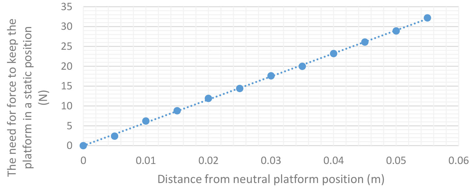
Figure 15.
Dependence between the force requirement to maintain the static position of the platform and the distance from the neutral position of the platform under different platform loads (2 IL).
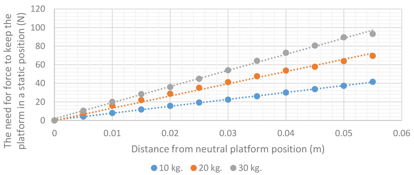
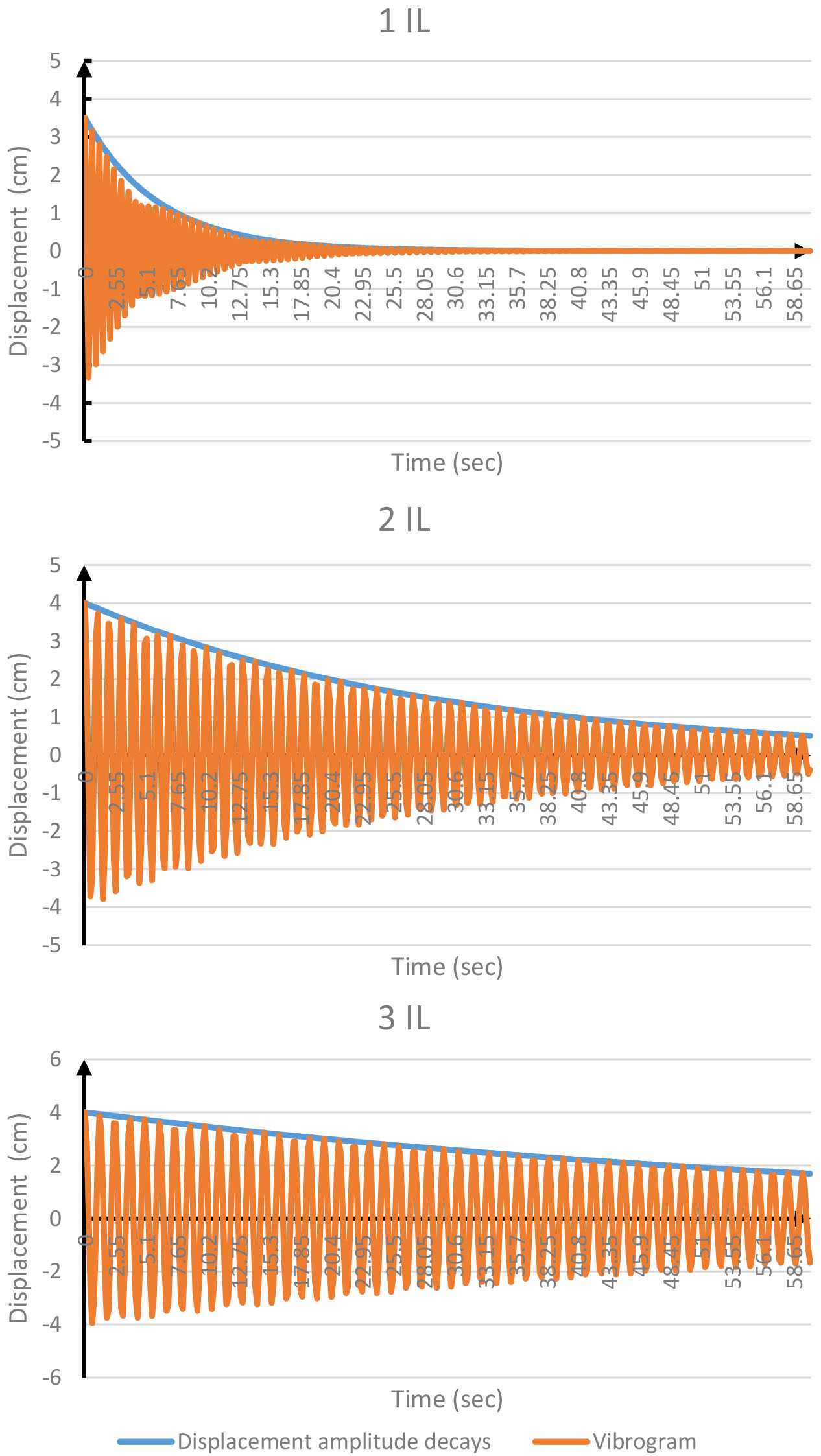
Figure 16.
Graphs of different IL vibrograms and amplitude decrease.
It is observed that there is a linear relationship between the force required to keep the board in a static position, and the distance at which the board is pulled (Fig. 14). The need for force is determined by the weight of the object placed on the board. This is illustrated in Fig. 16. It shows the relationship between the force required to maintain the static position of the board at different weights, and the different distance from the neutral position of the board. The greater the weight and distance from the neutral position, the greater the force requirement; but the force requirement changes disproportionately in all positions of the board. For this purpose, it is important to evaluate the direction factor of the Eq. (8). Ideally, the direction factor corresponds to the Eq. (9).
(9)
(10)
According to Fig. 14, it is observed that the higher the weight of the board, the higher the direction factor
Table 4
Direction factors of the calculated IL and board load functions
| IL | Board load weight (kg) | Function direction factor ( |
| 3 | 10 | 352.8 |
| 20 | 579.7 | |
| 30 | 846.2 | |
| 40 | 1066.4 | |
| 2 | 10 | 753.6 |
| 20 | 1316.1 | |
| 30 | 1797.4 | |
| 40 | 2397.2 | |
| 1 | 10 | 1971.7 |
| 20 | 3382.3 | |
| 30 | 4803.3 | |
| 40 | 6277.6 |
Table 5
Weighted values from one IL to another. They show how the required need for force to cause the board to move between different ILs differs
| IL exchange (from/to) | 3 | 2 | 1 |
|---|---|---|---|
| 3 | – | 0.46 | 0.17 |
| 2 | 2.18 | – | 0.38 |
| 1 | 5.76 | 2.64 | – |
Platform vibration damping evaluation results. In order to evaluate how the platform dampens vibrations, the damping factor was measured. Evaluate all 3 LI vibrograms and damping factors. Table 6 shows the oscillation and damping characteristics. Graph 16 shows that the damping of all 3 LI oscillations is exponential. Table 6 shows that for all 3 LI the damping factor is between 0
Table 6
The oscillation and damping characteristics of all IL
| Characteristic | 1 IL | 2 IL | 3 IL |
| Chain length (m) | 0.125 | 0.255 | 0.445 |
| Offset of the center of the board relative to the center of the platform frame (cm) | 3.500 | 4.000 | 4.000 |
| The force required to keep the board in a stable retracted position before the fluctuations began (N) | 310 | 196 | 132 |
| Period (s) | 0.502 | 1.007 | 1.238 |
| Number of cycles ( | 20 | 20 | 20 |
| Remaining amplitude from baseline after | 0.143 | 0.500 | 0.700 |
| Actual frequency ( | 10.649 | 6.243 | 5.077 |
| Logarithmic decrement over n number of cycles | 1.946 | 0.693 | 0.357 |
| Logarithmic decrement during cycle 1 | 0.097 | 0.035 | 0.018 |
| Damping factor ( | 0.015 | 0.006 | 0.003 |
| Damping constant ( | 1064.95 | 624.26 | 507.73 |
| Damping coefficient ( | 16.49 | 3.44 | 1.44 |
| Angular frequency omega ( | 10.65 | 6.24 | 5.08 |
The displacement of the platform board that results from the movement of the center of mass depends on the lengths of the supporting chains. The longer the length of the supporting structures, the greater the possible displacement of the board due to the displacement of the center of mass. This maximum board displacement size is defined for each of the LIs. At instability level 1 (IL), the displacement of the object on the board affected 0.66 cm. the displacement of the board relative to the platform frame; 2 IL – 0.79 cm; 3 IL – 0.91 cm; when assessing the influence of mass on the displacement of the board within the normal human mass range, no significant change is observed.
The amount of force required to move the platform board depends on the length of the supporting chains and the amount of body weight the board is loaded with. The longer the support chains and the lower the mass the board the lower the force required for the board to move. A force of 2.64 is required for a board displacement of 1 IL, compared to 2 IL and 5.76 times that of 3 IL. 3. This value can be quantified using a direction factor. It can be used to compare the instability created by different individuals and different LIs.
When evaluating vibrograms and damping factor values, very low values are observed: 1 IL – 0.015, 2 IL – 0.006, 3 IL – 0.003. The vibrations of the platform are damped, but the damping force affects only about 1 percent of vibration damping. The main parameters determining vibration damping are mass and chain length. Noticeably, there is a significant difference between 1 and 3 LI, which differs even 5 times. Although with low platform oscillation damping at all levels, it is significantly different between different LIs.
4.Discussion
In practice, single-plane equilibrium assessment platforms are not given enough attention to quantify the LI created by the platform, and the mechanical characteristics of the platform that are important for the qualitative instability characteristics. This study sought to, at least, partially complement the available knowledge on LI quantitative assessments. In our opinion, a weighting factor that allows for comparing different LIs can be a convenient tool in practical work. For example, comparing 1 LI (shortest chain) to 3 LI (longest chain), the weighting factor between them is 5.76. This means that a person of the same mass will need 5.76 times more force to pull the board out of the neutral position by the prescribed distance of 1 LI, than to do the same with 3 LI. From a practical point of view, this is important because the dosing of muscle strength at different LIs causes different effects: the higher the LI, the more precisely the muscle strength has to be distributed in order to maintain a proper ratio of body weight to support area, i.e. insufficient or excessive force can cause undesired displacement of the board, thus disrupting the ratio of the center of gravity to the area of the support required for proper balance. This quantitative assessment of instability can be useful in monitoring the rehabilitation effect of the same individual. For example, a person’s ability to maintain proper balance after a training cycle is no longer 1 LI, but 2 LI is likely to have improved 2.64-times, as 2 LIs require 2 times less force to bring the board out of neutral, so the integrated neurosensory and musculoskeletal system must be much more accurate. Further studies are needed to test this hypothesis.
It is important to emphasize that the mass of an object also affects the movement of the board: the higher the mass of the object, the more force is required to cause the board to displace. The available direction coefficients of the selected LI, and the corresponding body weight, create preconditions for comparing the balance of people of different body weights. It should be noted that when analysing living objects with increasing body weight, muscle mass and other anatomical structures usually increase in proportion [12]. With a higher body weight, a higher muscle mass is also likely, which in proportion to body weight could generate a proportionally greater muscle force required to cause the board to move. On the other hand, due to the increasing mass and the proportionally increasing muscle mass, a compensatory mechanism is possible. Therefore, the evaluation of mass may lose its value. For obese people, whose weight gain is due to excess fat tissue, this compensation mechanism is unlikely. It should be noted that this question was not the purpose of this article, so additional studies are needed to find expressions and a reasonable answer.
The movement of the center of mass of the body relative to the platform frame is a factor that also causes the displacement of the board. Accordingly: the greater the LI, the greater the displacement of the center of mass of the body, causing greater movement of the board. According to the data of previous publications, the postural fluctuation of young adults in the A-P direction is 0.2–0.5 cm, and in the M-L direction 0.35–0.45 cm [13]. Due to such fluctuations, the displacement of the board would not be large and, depending on the LI, the movement would be from 0.5 mm to 1 mm. In the group of individuals at high risk of collapse, the A-P variation was up to 15.4 cm
5.Conclusions
According to our research, it can be stated that the unstable balance platform LI creates for complex reasons, distinguishing as separate characteristics: 1) changes in the height of the board center that occur during board movement; 2) the formation of different angles of the inclined plane; 3) the occurrence of board movement as the movement of the center of gravity of the body changes 4) the occurrence of different force requirements for the occurrence of the required board movement in different LI.
It is likely that each of these characteristics act on different balancing mechanisms. It should be considered that each evaluated characteristic interacts with each other and determines a complex LI e.g. the fluctuation of the center of gravity results in an unacceptable ratio of the center of gravity to the area of support, so that the force generated by the corrective and compensatory movements of the limbs restores the ratio of the area of support to the center of mass appropriate for balance. The study does not allow for the estimation of the equilibrium level using the measured values, but it allows the numerical expressions to estimate the LI used for the equilibrium assessment, as well as to evaluate the mechanical properties of the platform through which instability is created. LI numerical expressions can be a useful tool in practical work in selecting the right LI for a training. Further studies are needed to allow the results of these measurements to be compared with the real balancing conditions.
Conflict of interest
None to report.
References
[1] | Ringhof S, Stein T. Biomechanical assessment of dynamic balance: Specificity of different balance tests. Hum Mov Sci. (2018) Apr; 58: : 140-7. |
[2] | Woollacott M, Shumway-Cook A. Attention and the control of posture and gait: a review of an emerging area of research. Gait Posture. (2002) Aug; 16: (1): 1-14. |
[3] | Maki BE, McIlroy WE. The Role of Limb Movements in Maintain ing UprightStance: The “Change-in-Support” Strategy. Phys Ther. (1997) May 1; 77: (5): 488-507. |
[4] | Gatev P, Thomas S, Kepple T, Hallett M. Feedforward ankle strategy of balance during quiet stance in adults. J Physiol. (1999) Feb; 514: (3): 915-28. |
[5] | Lubahn AJ, Kernozek TW, Tyson TL, Merkitch KW, Reutemann P, Chestnut JM. Hip muscle activation and knee frontal plane motion during weight bearing therapeutic exercises. Int J Sports Phys Ther. (2011) Jun; 6: (2): 92-103. |
[6] | Blackburn JT, Riemann BL, Myers JB, Lephart SM. Kinematic analysis of the hip and trunk during bilateral stance on firm, foam, and multiaxial support surfaces. Clin Biomech. (2003) Aug; 18: (7): 655-61. |
[7] | Amori V, Petrarca M, Patané F, Castelli E, Cappa P. Upper body balance control strategy during continuous 3D postural perturbation in young adults. Gait Posture. (2015) Jan; 41: (1): 19-25. |
[8] | Oliaei S, Ashtiani MN, Azma K, Saidi S, Azghani M-R. Effects of postural and cognitive difficulty levels on the standing of healthy young males on an unstable platform. Acta Neurobiol Exp. (2018) ; 78: (1): 60-8. |
[9] | Freyler K, Gollhofer A, Colin R, Brüderlin U, Ritzmann R. Reactive Balance Control in Response to Perturbation in Unilateral Stance: Interaction Effects of Direction, Displacement and Velocity on Compensatory Neuromuscular and Kinematic Responses. PLoS One. (2015) Dec 17; 10: (12): e0144529. |
[10] | Mierau A, Hülsdünker T, Strüder HK. Cortical evoked potentials associated with balance control after sudden perturbations. Med Sci Sports Exerc. (2015) May; 47: : 554-5. |
[11] | Mohazzabi P, Shankar SP. Damping of a simple pendulum due to drag on its string. J Appl Math Phys. (2017) ; 5: (1): 122-30. |
[12] | Daly RM, Saxon L, Turner CH, Robling AG, Bass SL. The relationship between muscle size and bone geometry during growth and in response to exercise. Bone. (2004) Feb; 34: (2): 281-7. |
[13] | Polastri PF, Barela JA. Adaptive visual re-weighting in children’s postural control. PLoS One. (2013) Dec 4; 8: (12): e82215. |
[14] | Wang F, Skubic M, Abbott C, Keller JM. Body sway measurement for fall risk assessment using inexpensive webcams. Annu Int Conf IEEE Eng Med Biol Soc. (2010) ; 2010: : 2225-9. |
[15] | Young DR. Mechanisms of sensory integration during postural adaptation [Internet]. 2020 [cited 2020 Nov 20]. Available from: https//uh-ir.tdl.org/handle/10657/6592. |

