
Smart textile device for shooter’s fingers movement monitoring
Abstract
BACKGROUND:
The manner in which shooters pull the trigger may significantly affect the shooter’s results. Shooting coaches are often not able to detect incorrect pull because of gun movement during the shot and recoil.
OBJECTIVE:
Development of the smart-textile based trigger pull monitoring system and demonstration of its ability to distinguish correct and wrong triggering techniques.
METHODS:
Two separated knitted resistive pressure sensors were integrated over III and II phalanges in the index finger fingerstall; single sensor was integrated over both III and II phalanges of the middle finger fingerstall. Resistance of the sensors was measured in a course of shots, performed by expert shooter, which simulated typical novice’s trigger pull errors.
RESULTS:
Sensors’ resistance recordings were made for following erroneous trigger pull motions: pulling of the trigger with index finger’s II phalanx instead of III; fast and jerky trigger pull (trigger tear-off); too fast release of the trigger after shot; and excessive grip force, applied by middle finger. For each type of erroneous movement, recordings waveforms included distinguishable features that characterised a particular type of error.
CONCLUSIONS:
The developed trigger pull monitoring system provides signals that could be used for recognition of the incorrect trigger pull motions during gun shots.
1.Introduction
In shooting, the manner in which the trigger of the firearm is pulled may significantly affect the shooter’s results, even if all other elements of the shooting techniques – aiming, breathing and position – are flawless [1, 2]. Often athletes do not notice how they pull the trigger, whether they excessively tighten forearm and palm muscles or feeds the shoulder forward – all this could lead to the firearm’s tilt just before the shot [3, 4]. The difficulty in detecting incorrect shooter’s actions when pressing the trigger is related to the firearm movement during the shot and recoil, which hides most of trigger pulling errors. Even an experienced coach may miss a slight movement of the firearm barrel, caused by incorrect fingers movement Although such tiny movements noticeably affect shooting result: deviation of the pistol barrel by 0.5 mm at 25-meter range cause bullet deflection by 8 cm, but at 50-meter range – already by 16 cm [5]. Generally, bullets scattering helps to diagnose shooting errors [6], but this method is only effective for multiple shots and cannot be used for single shot analysis. In addition, hit point position is not just the result of finger movement, but is a combination of several factors.
Numerous systems for assessment and training of the shooter’s index finger movements are described in literature and available at the market. The simplest training systems are forefinger spring type exercise devices, without any ability to monitor finger pressure [7]. Such trainers are usually a mock model of a firearm handle, and the training is targeted to the development of muscle memory and dexterity without making real shots.
More advanced systems enable monitoring of the shot. For instance, the Dvorak Instruments Inc. manufacture device that could be attached to real pistol (Beretta 92 or Glock) to measure displacement of the trigger [8]. Another example is finger pressure force measurement device, included in the SCATT shooting training kit [9, 10]. Researchers often relied on the sensors, mounted on the trigger [4, 11] while assessing trigger pull movement.
The abovementioned systems have number of drawbacks: they are only available for a limited number of gun models; they should be attached to the particular gun; they mostly are designed for evaluation of the index finger pressure force. The latter limit usability of such systems in evaluation of the proper firearm handle grip – it is important to assess, whether there is accidental pressure of the middle finger on the handle. Excessive middle finger pressure and grip with excessive muscular tension often causes the barrel of the weapon to move, thus affecting shooting results [1, 3]. In fact, the index finger must be the only finger that moves during shot [12].
The alternative approach, proposed in this paper, shifts the positioning of the finger movement monitoring device from weapon to the shooter’s hand. Use of wearables – smart gloves, equipped with pressure force sensors – allows estimate both index finger trigger pressure and grip pressure of other fingers. Smart glove could be designed using different sensors, for instance, elastomer-embedded silicon sensors [13] or graphite tensile-pressure sensors based on polydimethylsiloxane [14]. However, sensors available on the market are not flexible and thin enough, therefore they affect the sensitivity of the shooters’ fingers and hence compromise shooters performance. The entirely textile pressure force sensors offer high flexibility and will bend together with the finger without interference. For the shooters, that regularly use gloves (such as biathletes, policemen or military shooters) such sensors will be imperceptible.
Examples of the fingers pressure forces monitoring smart gloves are grip monitoring glove with embedded woven piezoresistive sensors, developed at Soongsil University [15], or basketball player glove with embedded knitted piezoresistive pressure sensors, developed at Riga Technical University [16].
The present paper describes the authors’ originally developed prototype of the shooter’s finger movement monitoring glove. For the simplicity purpose, the “glove” was reduced to the just two fingerstalls for the index and middle finger. The objective of the research was to prove the concept of the device: to demonstrate prototype’s ability to distinguish correct and wrong triggering techniques. Such demonstration is the first step in the further development of the fingerstalls as a tool for monitoring of the shooter’s finger movements.
2.Materials and methods
2.1Design of the shooter’s fingerstall
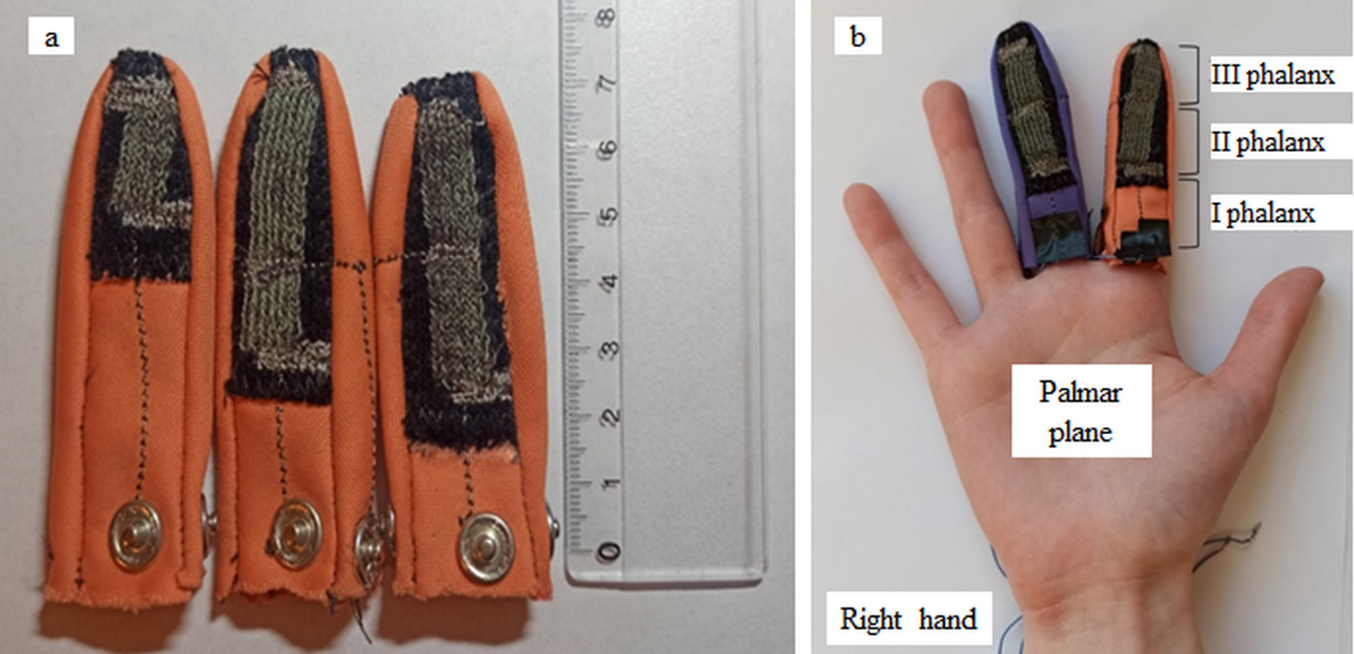
The originally developed pressure – sensitive fingerstalls were designed entirely from textile materials. Although knitting technology allows integrate both sensors and conductive lines into single item, the first prototype was assembled from separate sensing and conducting elements. Sensing elements were knitted from electrically conductive resistive threads [17] to form a piezoresistive material, whose electrical resistance decreases with increase in applied pressure [16]. Sensors were sewn to the fingerstall with cotton (nonconductive) yarn. Conductive paths were embroidered with electrically conductive silver-coated yarn [17]. Conductive paths ended with metal snaps, used to connect fingerstalls to data acquisition unit. The resistance of the unloaded sensors embedded in the fingerstalls ranged from 25 to 170 kOhms. Such a broad scattering is caused by different initial deformation of the sensor fabric during manual sewing.
Two type of fingerstalls were made: first had one sensing element on the distal (III) phalanx; second had two sensors – on the distal (III) and middle (II) phalanges. Following typical shooting technique [1], the trigger should be pressed by the index finger’s III phalanx, therefore index finger’s sensor should be located on the III phalanx. Attachment of the sensor to the II phalanx is important for the middle finger movement monitoring. Nevertheless, first experimental tests with real shooters demonstrated, that some of them could use II phalanx of the index finger to pull the trigger. Such athletes usually had fingers longer that other shooters. Therefore, fingerstalls with two sensors were used both for index and middle finger.
Figure 1.
Fingerstalls with one (left) and two (middle and right) textile pressure sensors (a); fingerstalls positioning over shooter’s hand (b).
The originally designed data acquisition unit (Fig. 2) enables simultaneous connection of 8 resistive sensors with resistances up to 1024 kOhms. Resistance measurement is based on registration of the voltage drop over sensor, fed by calibrated current. The unit uses 10-bit ADC, the measurement range could be adjusted from 2 kOhms up to 1024 kOhms, and the sampling rate is 160 s
Figure 2.
Data acquisition module (a) and measurement scheme (b).
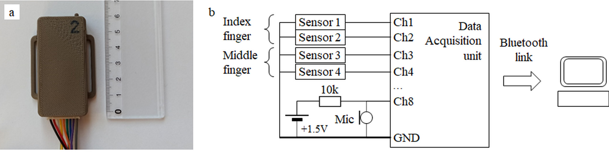
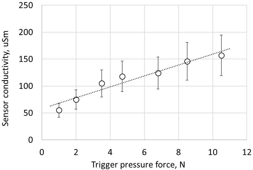
Figure 3.
Calibration of the III phalanx sensor.
2.2Calibration and normalisation of the textile sensors
Before measurements of the finger pressure during real shooters training, textile sensors were calibrated individually to assess repeatability of pressure measurements. Calibration was made by application of weights of the known mass in the range from 0.100 kg up to 1.07 kg. The weights were applied via loading pad, having a contact area equal to one of the gun trigger and hereby simulating loading pattern during real shot. The range of forces, applied to the sensors in such a manner, fully cover typical range of the trigger pulling forces for sport weapons (50–150 N, [18]), although is not enough for military firearms, where trigger pulling force may exceed 400 N [19]. As the present paper concentrates on sport shooters, calibration force range is adequate. Figure 3 show an example of calibration curve, obtained for III phalanx sensor, demonstrating close to linear relationship between sensor’s conductivity and loading force.
During calibration, sensors were loaded both while keeping finger straight and for bent finger. Between measurements, the fingerstalls were removed and then put back. The repeatability-related uncertainty, evaluated using data for both straight and bent finger measurements, comprises 15% for the III phalanx sensor, which is generally compatible with typical inaccuracy of elastomer-based sensors. The uncertainty for II phalanx sensor was 24%. Note, that when uncertainty is evaluated, using only straight finger measurements, uncertainty for II phalanx sensor was only 7%, but for II phalanx sensor – 15%. This indicates that finger bending increases measurement inaccuracy.
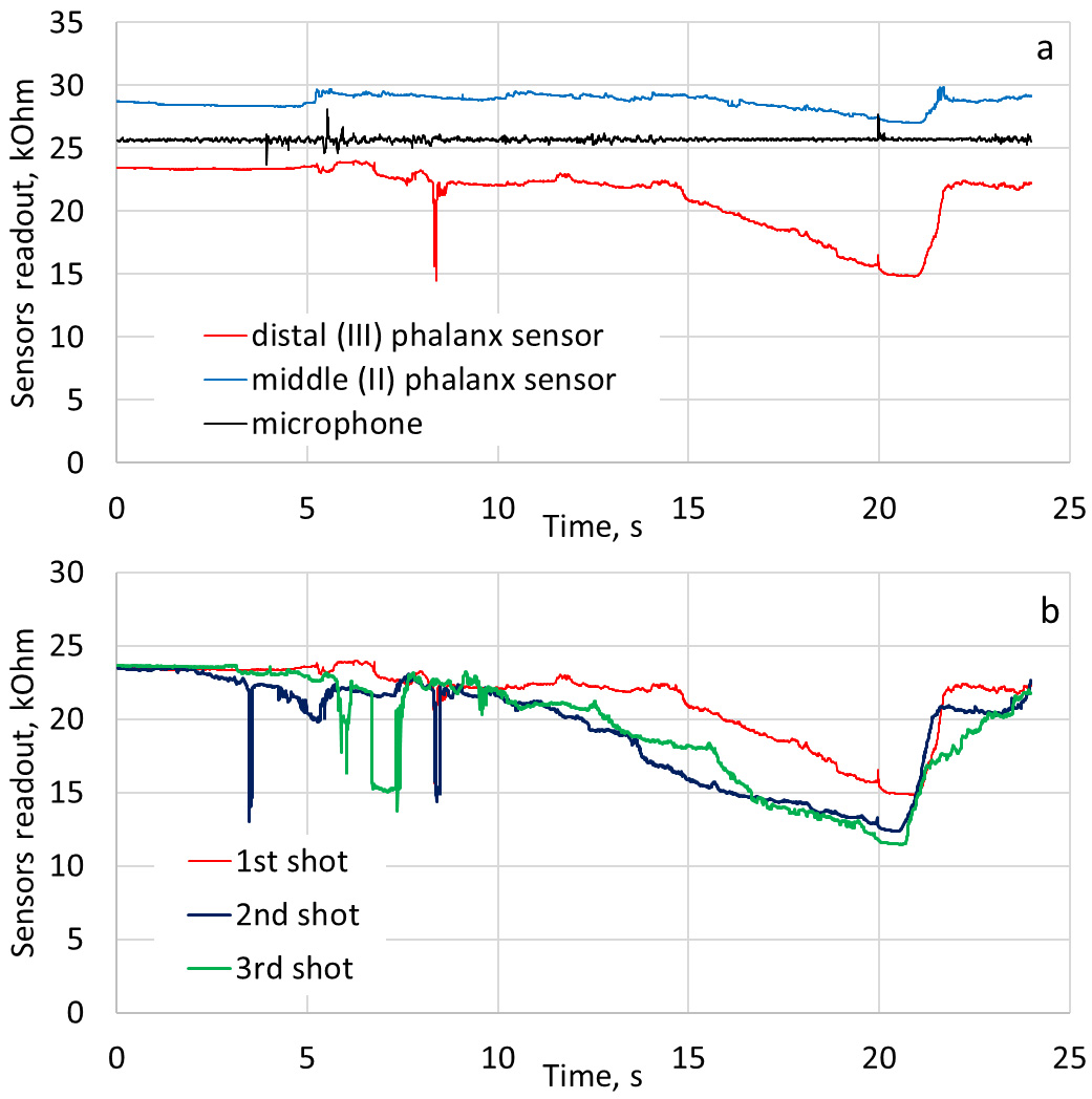
Despite of high uncertainty in separate measurements, textile sensors demonstrates good repeatability in a single measurement series, providing the fingerstalls are not removed between shots (Fig. 4b). Different sensors initially have different baseline resistance value at “no load” conditions (Fig. 4a), and even the same sensor would change the baseline being removed and put back. To be able to compare data from different sensors and from same sensor in different measurement series, sensors’ data was normalised to the baseline value, calculated as an average of the sensor readout at first 100 data points (
Figure 4.
Typical single shot readout from distal phalanx sensor, middle phalanx sensor and microphone (a) and III phalanx sensors record from 3 sequential shots (b). Microphone output voltage is recalculated to kOhms by data acquisition unit internal calculation algorithm. Note the spike at 20
2.3Evaluation of shooting performance
The present research was limited to demonstration of the usability of the designed fingerstall for evaluation of sport shooters trigger pull movements. Two volunteer shooters were involved: a national champion level shooter that used a pneumatic pistol Steyr LP 10 with single-stage trigger, and a shooting coach that used the same model pistol with two-stage trigger. The main selection criterion for the shooters was experience and ability to perform correct shot and to simulate typical novices’ errors. For both pistols, trigger pull effort was 4.90 N.
Each shooter performed series of “dry fire” (with no bullet) and ordinary shoots, trying perform on their best. After the series of perfect shoots, shooters simulated typical trigger pooling mistakes: pulling the trigger with II phalanx of index finger; tearing off the trigger at the beginning of the shot; tearing off trigger at the end of free run; trigger tear off at the end of the pull; early (
Figure 5.
Normalised recording of three sequential shots with single-stage trigger (a) and two-stage trigger (b). In both cases shot instance corresponds to 20th second. First shot differs from following ones due to shooters adaptation to the fingerstalls.
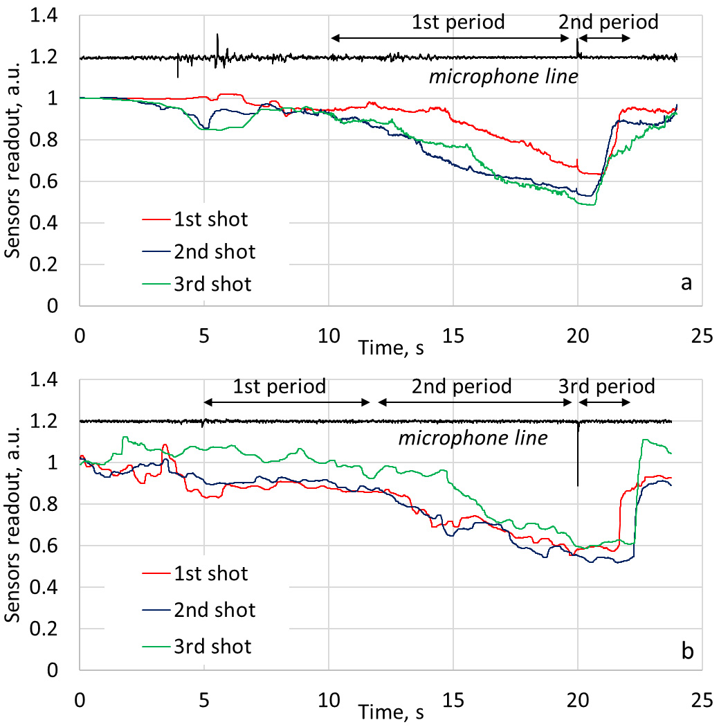
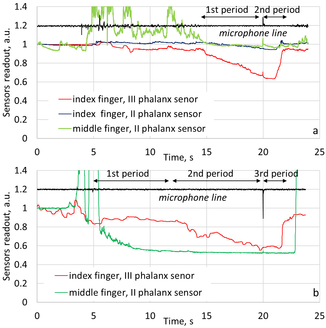
Figure 6.
Normalised recording of index and middle finger sensors for shots with single-stage trigger (a) and two-stage trigger (b). Notice nearly invariable signal from middle finger before the shot, typical for experience shooters.
3.Results and discussion
3.1Correct shots recordings
Figures 5 and 6 summarizes typical normalised measurement results correct shots. Figure 5 demonstrates typical features of the correct shot, made by experienced shooters using single stage trigger pistol (Fig. 5a) and two-stage trigger pistol (Fig. 5b). Two phases of movement could be distinguished at the single-stage trigger pull recording (Fig. 5a). The first phase before the shot take about 85% of the whole shot cycle. This phase is attributed by nearly steady decrease in index finger sensor’s resistance, which, in turn, corresponds to the steady increase in trigger pull force. In a series of shots, the lowest value of resistance differs slightly from shot to shot, that could be explained by alteration of the finger position over the trigger. This alteration especially expressed at the first shot in a series, while the following shots are much closer to each other. This indicates adaptation of the shooter: during the second and third shots, the shooter adjusted position of index finger and place trigger in the middle of distal phalanx. The second phase is short and comprises about 15% of the shot cycle. This phase is attributed by nearly constant sensor’s resistance immediately after the shot, which reflex experienced shooter ability to keep after-shot pressure over the trigger. Further sharp increase in resistance indicates that trigger is released, and the pressure over the sensor dropped sharply.
For the two – stage trigger, finger movement could be divided into three phases (Fig. 5b). The first phase of relatively low steady force corresponds to the idle trigger running. In the second phase, as the trigger spring begins to resist, the trigger pulling force increases. This stage is attributed by steady decrease in sensor pressure, similar to one observed in the phase I in single – stage trigger shot. The duration of the first and second stages are nearly the same, and together they take up to 85 % of the shot cycle. Such a division of the pre-shot trigger pulling is arbitrary: the more correct is trigger pulling movement, the less noticeable is the transition between two stages. In the third, after-shot phase, as in the case of single – stage trigger, the hold of trigger pressure for about 1 second after shot is important. This hold is clearly seen on the record from experienced shooter. As in the previous case, after-shot phase ends with fast release of the trigger.
Figure 6 compares signals, recorded during correct shot from index and middle fingers. Signal of the II phalanx sensor (Fig. 6a) alters much less in comparison with III phalanx signal: for the presented data relative change of the III phalanx sensor signal level is 42%, but for II phalanx sensor – only 7%. Such a small signal could be caused by deformation of the sensor’s fabric as the shooter’s finger folds, not by the direct force applied to the sensor. Small signal from the II phalanx indicates not only correctness if the trigger pull movement, but also that the location of the fingerstalls sensors exactly matches the length of the shooter’s phalanges. For some cases, when fingerstall was too short and II phalanx sensor partially overlaps III phalanx, II phalanx sensor’s signal during the shot may have the same alteration as III phalanx sensor’s signal, and even exceed it. From the above one can conclude that for the accurate results it is necessary to adjust the dimensions of the fingerstalls for each shooter individually, so that the location of the sensors more precisely corresponds to the anatomical characteristics of the shooter.
Although at the initial stages of the shot middle finger sensor signal demonstrated noticeable disturbances (Fig. 6a and b), possibly caused by weapon reload or just loss of contact in the sensor’s circuit, at the most important phases of the shot the middle finger signal of experienced shooter was nearly constant. Alongside such stabilisation of the middle finger, pressure starts about 2 seconds after index finger started movement (Fig. 6a). This peculiarity is observed for both shooters, participated in the measurements, and for all correct shots, therefore it should be taken into account when assessing the correctness of the middle finger movement. Recordings at Fig. 6 also shows that the release of the middle finger occurs later than one of the finger.
Summarizing various correct shot signal recordings, one could conclude that shot – to – shot variations in the recorded signals often hide transition between idle trigger running and work stroke. Therefore, for the purpose of further analysis, in the case of two-stage trigger, is not reasonable to divide pre-shot phase into two separate stages. For the analysis of incorrect shots, only two phases – pre-shot and after-shot – will be analysed.
3.2Incorrect shots recordings
First shooter’s error, simulated by experienced shooter was pulling of the trigger with II phalanx. Normally, the trigger should be pressed with III phalanx, but novice shooters may often pull the trigger with a joint between III and II phalanges, or may start movement with a proper finger position, but further finger slides and II phalanx comes in contact with trigger. Index finger recordings at Fig. 7 demonstrates typical manifestation of such error. Low level of the II phalanx sensor signal indicates significant load, i.e. shooter pull trigger mainly by II phalanx. Note that just before the moment of the shot, the resistance of the III phalanx sensor increases slightly, indicating a decrease in the force, applied to the sensor (red arrow at Fig. 7). This means that III phalanx load is, in fact, released. Load of the II phalanx sensor, in turn, increases (resistance decreases, indicated by blue arrow at Fig. 7). Such a “shift” of the load from III to II phalanx corresponds well to the above “sliding” of the finger over the trigger.
Figure 7.
Manifestation of incorrect shot when trigger is pulled by II phalanx of index finger. Arrows indicates typical inversion in phalanges load: while force, applied by II phalanx increases (sensor’s readout decreases), force of III phalanx decreases (sensor’s readout increases).
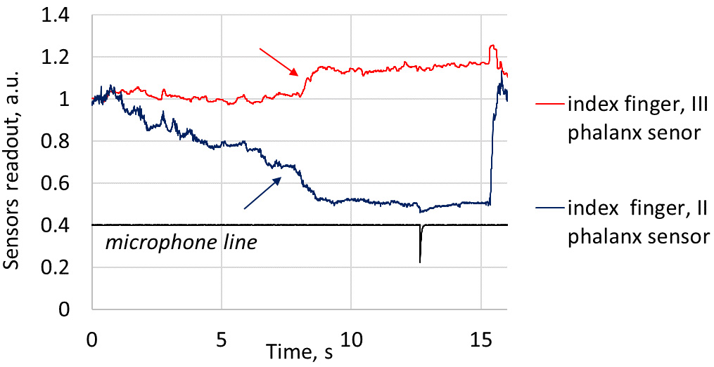
Figure 8.
Manifestation of incorrect shot – trigger tear off at the beginning, in the middle and at the end of trigger pull motion. Note shortened duration of the pre-shot phase when trigger is teared at the beginning and in the middle of the motion. Arrows indicates sharp increase of the pulling force, that is typical such type of trigger pull error. Note, that there is no such increase when the movement is correct.
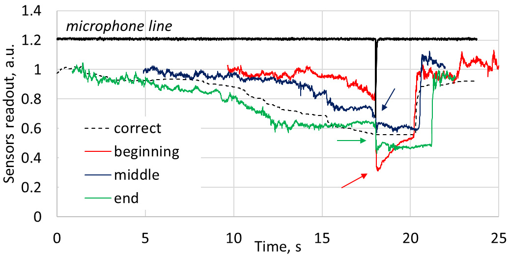
Second error, or rather group of errors, is characterised by too fast and jerky trigger pull – trigger tear-off. The tear off may occur at the beginning, in the middle and at the end of the trigger pull motion; manifestation of all these options in index finger recordings are presented at Fig. 8. When the trigger tear-off occurs at the beginning of the pull movement (Fig. 8, red line), the total pull time is reduced, as the shooter rapidly progress through load-free run and trigger work stroke stages. At the moment of the shot, the result of such a rapid pressing or tearing is visible as a sharp drop in sensor’s resistance (Fig. 8, red arrow), that corresponds to a rapid increase in force, applied to the III phalanx sensor.
The tear-off in the middle of the pull movement (Fig. 8, blue line) takes place when the shooter progress through load-free run in a correct way, but pull too quickly at trigger working stroke. The duration of the total pull time is reduced as well, although in a less extent, than in the previous case. And, like in the previous case, stepwise drop in sensor resistance, i.e. increase in trigger pull force is clearly visible (Fig. 8, blue arrow).
The tear-off at the end of the pull movement (Fig. 8, green line) is not characterised by reduction in the total movement time, because the shooter pull correctly during load-free run and working stroke phases, but tear the trigger just before the shot moment. In this case, too, sharp decrease in sensor’s resistance (Fig. 8, green arrow) is a good indicator of error.
Third error is a fast release of the trigger immediately after shot. Until the very moment of the shot, the shooter pulls the trigger correctly, but immediately after the shot, release the finger without holding it about 1 second with a constant force. This type of error could be easily seen on the III phalanx sensor recording as a rapid increase in sensor’s resistance as the pressure on the III phalanx sensor is dropped rapidly (Fig. 9).
Figure 9.
Manifestation of incorrect shot – too fast release of the trigger after shot. Note typical shortening of the interval between instant of shot (black spike at microphone line and release of the trigger pull (red and blue arrows).
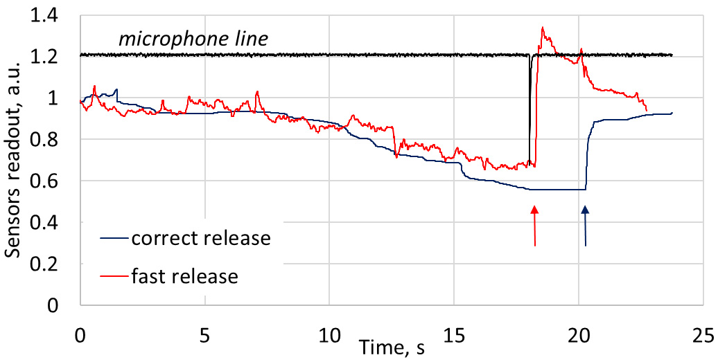
Table 1
Peculiarities of correct and erroneous trigger pull motion in pistol shooting
| Type of motion | Characteristics |
|---|---|
| Correct motion | Smooth increase in pull force measured by index finger III phalanx sensor. Force, measured by index finger II phalanx sensor is lower than one measured by III phalanx sensor. Duration of the pull phase is around 11–18 seconds (typically 14–15 second). There are no changes in a pull force in the moment of shot. Force is applied to the trigger about 1 second after moment of shot. Force, measured with middle finger sensor has no oscillations in a course of shot. |
| Trigger pull with index finger’s | Force, measured by index finger III phalanx sensor is lower than one measured by II |
| II phalanx | phalanx sensor. III phalanx force decreases while II phalanx force increase in a course of the shot. |
| Trigger tear off in the beginning | Duration of the pull phase is shortened, sharp increase in pull force in the moment of |
| and middle phase of pull | shot is observed. |
| Trigger tear off in the end of pull | Sharp increase in pull force in the moment of shot is observed. |
| Fast trigger release after shot | Pull force drops during period less than one second after shot. |
| Excessive grip by middle finger | Force, measured with middle finger sensor demonstrates oscillations, amplitude of the middle finger sensor signal is increased. |
Figure 10.
Manifestation of incorrect shot – excessive and unstable middle finger pressure. In the case of incorrect shot, middle finger readout is noticeably lower, that corresponds to higher middle finger pressure. Excessive tension of the middle finger often causes instabilities in finger pressure (red arrows). Note, that index finger recording (red dotted line) shows typical signs of trigger tear-off: shortened duration of the pull phase, and overshoot (dotted arrow), similar to those at the Fig. 8.
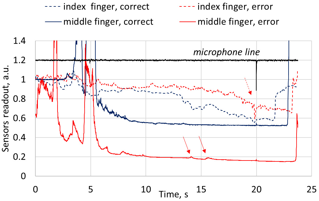
Fourth error is related to the wrong operation of the shooter’s middle finger. Novice shooters often tend to apply excessive grip force with middle finger. Over-tension of the middle finger may “block” correct operation of the index finger, causing non-smooth index finger movement and resulting in trigger tear-off. Alongside, failing to maintain constant middle finger force, shooter may unintentionally turn firearm from target direction, as a result shot miss the target. Figure 10 demonstrates typical manifestation of such error in finger sensors’ recordings. For incorrect shot, middle finger signal is noticeably lower, then one for the correct shot, that corresponds to the higher middle finger pressure. Slight oscillations in the recording (red arrows) indicates variation in pressure. Although incorrect shot was simulated by experienced shooter, index finger recording (red dotted line) exhibits typical features of the trigger tear-off: shortened pull phase and pressure overshot at the moment of shot (dotted arrow). This confirms statement, that even experienced shooter could not perform proper shot if his middle finger is overstrained.
3.3Discussion
The obtained pilot results demonstrated that developed shooter’s trigger pull motion monitoring system prototype can distinguish correct triggering technique from incorrect techniques, simulated by experienced shooters. The recorded incorrect triggering waveforms exhibited number of peculiarities: decrease of the force, applied by index finger III phalanx sensor, and increase of the force of the II phalanx sensor; shortening of the duration of the pull phase; sharp increase in pull force in the moment of shot; pull force drops during period less than one second after shot; oscillation of the force, applied with middle finger. These peculiarities are summarised in the Table 1.
Authors meet certain difficulties to compare obtained results with data from other sources. Analysis of the papers, published so far, revealed, that main parameters, related to the triggering, was average trigger pull force [11], parameters, derived from normalised trigger force slope [4], cleanness of triggering and timing of triggering [20, 21], location of the triggering instant within athlete’s cardiac cycle [22]. The comprehensive review of shooting performance affecting parameters could be found in [23]. Reviewed papers did not provide detailed evaluation of the fingers’ movement waveforms during triggering, there are no data concerning involvement of separate index finger phalanxes and middle finger in the triggering movement. From this point of view, presented paper is innovative. From other point, authors should in future put efforts in establishing correlations between data, provided by smart fingerstalls and parameters, commonly used in shooter performance analysis. Still, developed prototype adequately estimates, e.g., total shot time. Time, derived from Figs 4–6 for correct shot (ranging 7–10 seconds) in in a good agreement with shot time reported in [20] for pistol shooters and equal to 7.69
The developed entirely textile fingerstall provided sufficient level of the user comfort: expert shooters admitted that fingerstalls are soft enough, does not reduce sensitivity of the fingers and does not distort shooting process.
The present research was limited to the simulation of the incorrect shots by experienced shooter, which used a pneumatic pistol. Another limitation is small number of shots, performed by each shooter for each shot type. Even such limited results demonstrated, that in the single series of shots, the first shot differs from the following ones, as shooter becomes accustomed to the firearm and fingerstalls itself. Thus, to obtain reliable results, series of shots should be performed. Still, the question of waveforms repeatability between series, obtained after shooter removed the fingerstalls and put them back, or series, obtained at different days with the same shooters, was not explored within the scope of this paper. Further development of the system and methodology requires collection of data from multiple series of shoots, performed by both experienced and novice shooters, as well as extension of gun types to short and long-barrelled pneumatic and fire guns. Such sensor recording database would allow to elaborate “good shot standard”, i.e. find signal waveform that corresponds to the correct trigger pull motion. Important question, related to such standard – would it be universal, i.e., fits for all shooters, or should it be developed individually for each person.
Another essential stage of development is automated classification and recognition of correct and erroneous trigger pull patterns that could be achieved, for instance, by extraction of specific numerical characteristics of the signals with following cluster analysis or by means of neural network.
In general, this pilot study for the first time proved the concept of the entirely textile sensor-based shooter’s finger movements monitoring system and demonstrated it potential for the detection of the incorrect trigger pull motion, that justify further development of the system.
4.Conclusion
The present paper proved the concept of the shooter’s trigger pull motion monitoring system, that enable recording and visualisation of the forces, applied to the trigger during shot separately by index finger phalanges and to the handle by middle finger.
Recorded waveforms differ for correct trigger pull motion and for motions, where some type of trigger pull error was expressed. Pulling of the trigger with index finger’s II phalanx instead of III is characterised by inversion in II and III phalanxes recordings: force, applied by III phalanx decreases, while force, applied by II phalanx increases in a course of trigger – pull motion. Trigger tear-off is characterised by shortened duration of the pull phase before shot and rapid increase of applied force in the moment of shot. Too fast trigger release after shot is characterised by shortened time period between moment of shot and drop in finger applied force. Excessive grip force, applied by middle finger is attributed by increased amplitude of the middle finger sensor signal, as well as with oscillations of force in a course of shot.
The reliability of the obtained results is limited by the pilot nature of the study that involved only two expert level shooters and was based on simulation of the novices’ mistakes, not by involvement of the novices itself. Nevertheless, the study demonstrated potential of the developed system and becomes the base for the further development. On could expect that the revealed features of the correct and incorrect shots are general, i.e., would persist in the future studies when a broader cohort of shooters will be involved, and could become the basis for the elaboration of shooters training tools.
Acknowledgments
This work has been partially financed in the framework of Riga Technical University research grant 01000-1.4-e/25 “Smart textile system for monitoring the pressure of the shooter’s finger on the gun trigger”.
Conflict of interest
None to report.
References
[1] | Saiva L. Basics of bullet shooting. Riga: Latvian Sport Pedagogy Academy; (2005) (in Latvian). |
[2] | Laaksonen MS, Finkenzeller T, Holmberg H-C, Sattlecker G. The influence of physiobiomechanical parameters, technical aspects of shooting, and psychophysiological factors on biathlon performance: A review. Journal of Sport and Health Science. (2018) ; 7: (4): 394-404. doi: 10.1016/j.jshs.2018.09.003. |
[3] | Yur’yev AA. Competitive Shooting: Techniques and Training for Rifle, Pistol, and Running Game Target Shooting, Washington, DC: National Rifle Association of America; (1985) . |
[4] | Sattlecker G, Buchecker M, Gressenbauer C, Müller E, Lindinger S. Factors discriminating high from low score performance in biathlon shooting. Int J Sports Physiol Perform. (2017) ; 12: (3): 377-384. doi: 10.1123/ijspp.2016-0195. |
[5] | Todorović Z. ISSF Coach Course, Pistol Shooting, ISSF; (2020) [cited 2021 Jul 15]. Available from: https://www.issf-sports.org. |
[6] | Cleckner RM. Long Range Shooting Handbook: The Complete Beginner’s Guide to Precision Rifle Shooting. Nashville TN: North Shadow Press; (2016) . |
[7] | Trigger Trainer [homepage on Internet]. Full-Scale Tactics Inc.; (2021) [cited 2021 Jul 15]. Available from http://www.thetriggertrainer.net/. |
[8] | Trigger Pull Trainer for Full Size Glocks [homepage on Internet]. Dvorak Instruments Inc.; (2021) [cited 2021 Jul 15]. Available from https://www.dvorakinstruments.com/. |
[9] | Trigger sensor [homepage on Internet]. Moscow region: SCATT Electronics LLC; (2021) [cited 2021 Jul 15]. Available from https://www.scatt.com/scatt-trigger-sensor. |
[10] | Zanevskyy I, Korostylova Y, Mykhaylov V. Aiming point trajectory as an assessment parameter of shooting performance. Human Movement. (2012) ; 13: (3): 211-217. doi: 10.2478/v10038-012-0024-3. |
[11] | Sattlecker G, Müller E, Lindinger S. Biomechanical factors of biathlon shooting in elite and youth athletes. In: Müller E, Lindinger S, Stöggl T, eds. Science and skiing. Aachen: Meyer & Meyer Verlag; (2009) . pp. 641-6. |
[12] | Findley B. 7 trigger control errors and how to fix them [homepage on Internet]. Multibriefs: B. Findley; (2015) [cited 2021 Jul 15]. Available from https://exclusive.multibriefs.com/content/7-trigger-control-errors-and-how-to-fix-them/law-enforcement-defense-security. |
[13] | Ying M, et al. Silicon nanomembranes for fingertip electronics. Nanotechnology. (2012) ; 23: : 344004. doi: 10.1088/0957-4484/23/34/344004. |
[14] | Wu Y, et al. High resolution flexible strain sensors for biological signal measurements, 2017 19th International Conference on Solid-State Sensors, Actuators and Microsystems (TRANSDUCERS), (2017) . pp. 1144-1147. doi: 10.1109/TRANSDUCERS.2017.7994255. |
[15] | Kim G, Vu C, Kim J. Single-layer pressure textile sensors with woven conductive yarn circuit. Applied Sciences. (2020) ; 10: : 2877. doi: 10.3390/app10082877. |
[16] | Oks AJ, Oks A, Katashev A, Eizentals P. Smart glove usage possibility for basketball training: proof of concept. Proc. of International Scientific Conference Society Integration Education, Rezekne. (2019) ; 4: : 235. doi: 10.17770/sie2019vol4.3991. |
[17] | Oks A, Katashev A, Litvak J. Knitted Resistive Fabric: Properties and Applications. Materials Science: Textile and Clothing Technology, RTU, (2015) : 9. doi: 10.7250/mstct.2014.005. |
[18] | International Shooting Sport Federation [homepage on Internet]. Federation; (2021) [cited 2021 Jul 15]. Available from https://www.issf-sports.org/. |
[19] | Kreider J. Trigger pull testing M16A2 Rifle & M4 Carbine – Final Report. US Army Small Arms Branch. Technical Report Number: SMCAR-ES-93-1, (1993) . |
[20] | Olsson E, Laaksonen MS. Key technical components for air pistol shooting performance. Int. J. Perform. Analysis in Sport. (2021) ; 21: (3): 348-360. doi: 10.1080/24748668.2021.1891820. |
[21] | Ihalainen S, Kuitunen S, Mononen K, Linnamo V. Determinants of elite-level air rifle shooting performance. Scand J Med Sci Sports. (2016) ; 26: : 266-74. doi: 10.1111/sms.12440 PMID:25850700. |
[22] | Mets T, Konttinen N, Lyytinen H. Shot placement within cardiac cycle in junior elite rifle shooters. Psychology of Sport and Exercise. (2007) ; 8: : 169-77. doi: 10.1016/j.psychsport.2006.02.0022. |
[23] | Spancken S, Steingrebe H, Stein T. Factors that influence performance in Olympic air-rifle and small-bore shooting: A systematic review. PLOS ONE. (2021) ; 16: : e0247353. doi: 10.1371/journal.pone.0247353. |

