
Ultrawide-angle optical system design for light-emitting diode-based ophthalmology and dermatology applications
Abstract
BACKGROUND:
Compared to laser, light-emitting diodes – non-coherent and divergent light sources requires that the developed optical system support steering and focusing of light on the desired target when acquiring information regarding human tissues.
OBJECTIVE:
A new optical system with an ultrawide angle was designed to cover large areas of the eye, including facial areas near the eye, in order to overcome the limited field of view of optical systems used for ophthalmology and dermatology applications.
METHODS:
To achieve a compact and handheld optical system for ophthalmology and dermatology applications, a contrast auto-focus (AF) method must be used, and the weight reduction of the AF group is considered during the design process to satisfy the effective focal length (EFL), back focal length (BFL), and front focal length (FFL) in the proposed optical system using Gaussian-bracket method.
RESULTS:
The designed optical system can focus from infinity to a magnification of
CONCLUSIONS:
We have designed an ultrawide-angle optical system for compact optical systems that are suitable for high-performance ophthalmology and dermatology applications.
1.Introduction
Compared with medical imaging modalities such as X-rays, computed tomography (CT), positron emission tomography (PET) and magnetic resonance imaging (MRI), the optical imaging modality is specialized in diagnosis in the field of ophthalmology owing to its limited penetration depth and scattering effects [1, 2, 3, 4]. In optical imaging, light sources are used to obtain information regarding the ocular tissues of the human eyes, including damage to the optic nerve fiber and optic disc in the eye [2, 3, 5]. Being a coherent and non-divergent light source, laser technology is the gold standard in ophthalmology [5, 6, 7]. Compared with lasers, light-emitting diodes (LEDs) are non-coherent and divergent; thus, specialized optical systems are needed when LED sources are used for steering the light and focusing it on the target [8, 9, 10].
If the disease region is spread across a large area extending beyond the eye and the facial region, physicians must maneuver the imaging probes at different positions within and outside the eyes, and the acquired images must be processed to show the entire region because typical optical systems used for ophthalmology applications, such as optical coherent tomography and slit-lamp bio-microscopy systems, have a limited field of view (FOV) [11]. Compared with lasers, LEDs are relatively compact light sources, allowing designed optical system to be handled by users with more ease in diagnosis. Therefore, we developed ultrawide-angle optical systems for ophthalmology and dermatology applications, as illustrated in Fig. 1.
Figure 1.
Conceptual block diagram of the designed ultrawide-angle optical system for ophthalmology and dermatology applications: (a) focused in the eye, (b) unfocused to cover a wide area, and (c) focused outside the eye.
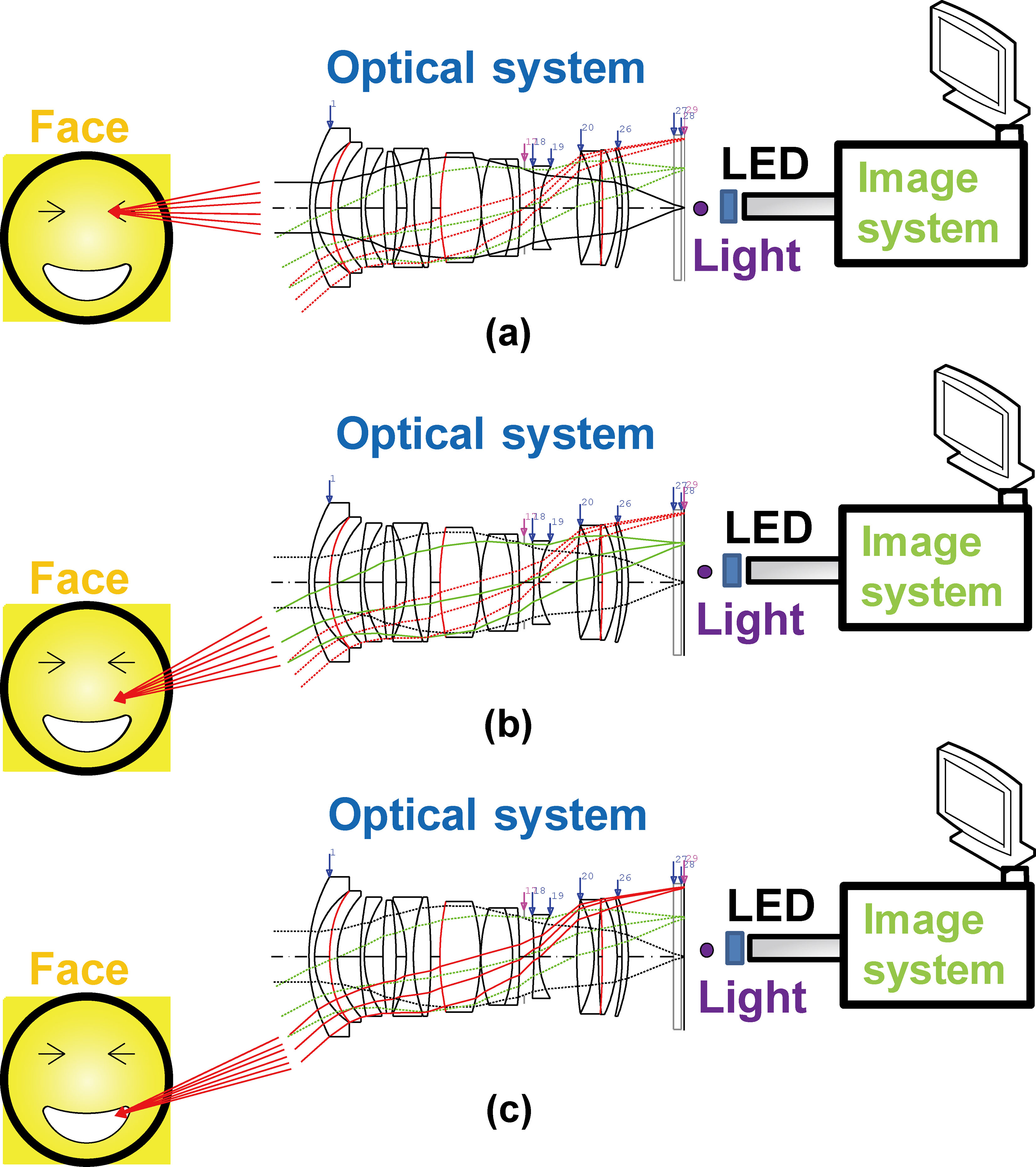
In Fig. 1a, the designed optical system supports focusing of LED within the eye. Therefore, a similar configuration can be employed for both optical coherent tomography and slit-lamp bio-microscopy systems. Figure 1b shows that the designed optical system is able to increase the FOV to facial areas beyond the eye. As illustrated in Fig. 1c, the designed optical system can allow focusing of LED light to beyond the eyes by moving the LED light source mechanically or electronically. This can be helpful if the facial areas outside the eye need to be diagnosed by a physician. Therefore, our designed optical system supports imaging across a wide FOV, as depicted in Fig. 1.
The near-infrared and visible light for ophthalmology and dermatology applications are typically in the wavelength range of 400 to 700 nm, as light of these wavelengths is readily absorbed by eye and skin tissues [12, 13]. The wavelength range used is typically determined according to the type of tissue, such as melanin, oxyhemoglobin, or de-oxyhemoglobin to reveal fundamental information regarding diseases related to the eye and facial skin [14, 15]. Similar to lasers, LEDs must effectively generate light signals with adequate amplitudes, but there are energy and power limitations for avoiding damage to human tissues for each wavelength, as defined by ANSI standards [16]. Additionally, the high optical aberrations and low spatial resolutions caused by LED light sources during the use of optical systems may deteriorate the signal quality of the information received from human tissues [17, 18, 19, 20]. Therefore, any ultrawide-angle optical system with LED light sources must be properly designed for ophthalmology and dermatology applications in order to generate proper illumination with adequate power. The detailed architectures and design methods of the optical system are described in Section 2. The performance data for the developed optical system are presented in Section 3. Section 4 concludes the paper.
2.Paraxial design
To design an optical system that satisfies the given specifications, each group in the system should be assumed as a thin lens, to determine its focal length. Subsequently, it should be converted into a thick-lens system. This is a paraxial design method that requires considerable time and many iterations of trial and error to satisfy the given specifications [20]. In this respect, several fundamental optical systems have been published recently, which can be applied to jump start the fundamental paraxial design. Figure 2 shows the lens layout for Example 1 of patent JP2016-012034 with infinite objectives [21]. In this optical system, two lens groups are moved while focusing [22].
Figure 2.
Optical layout for JP2016-012034, Example 1.
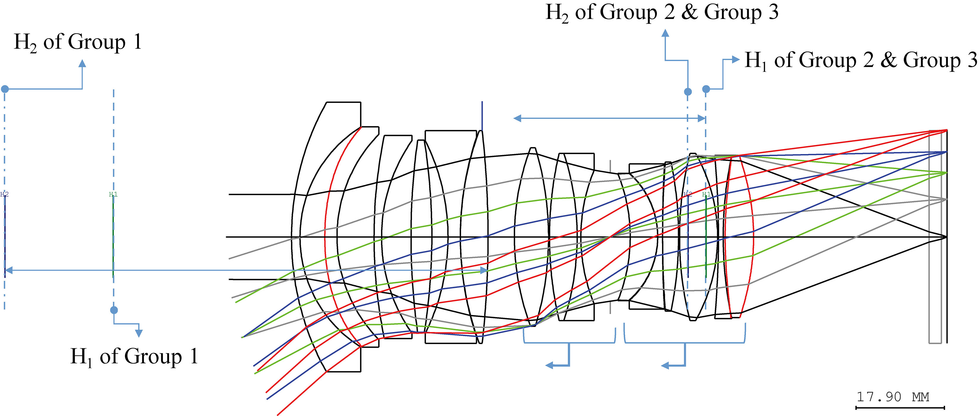
Figure 3.
Optical layout for KR2014-0124286, Example 2.
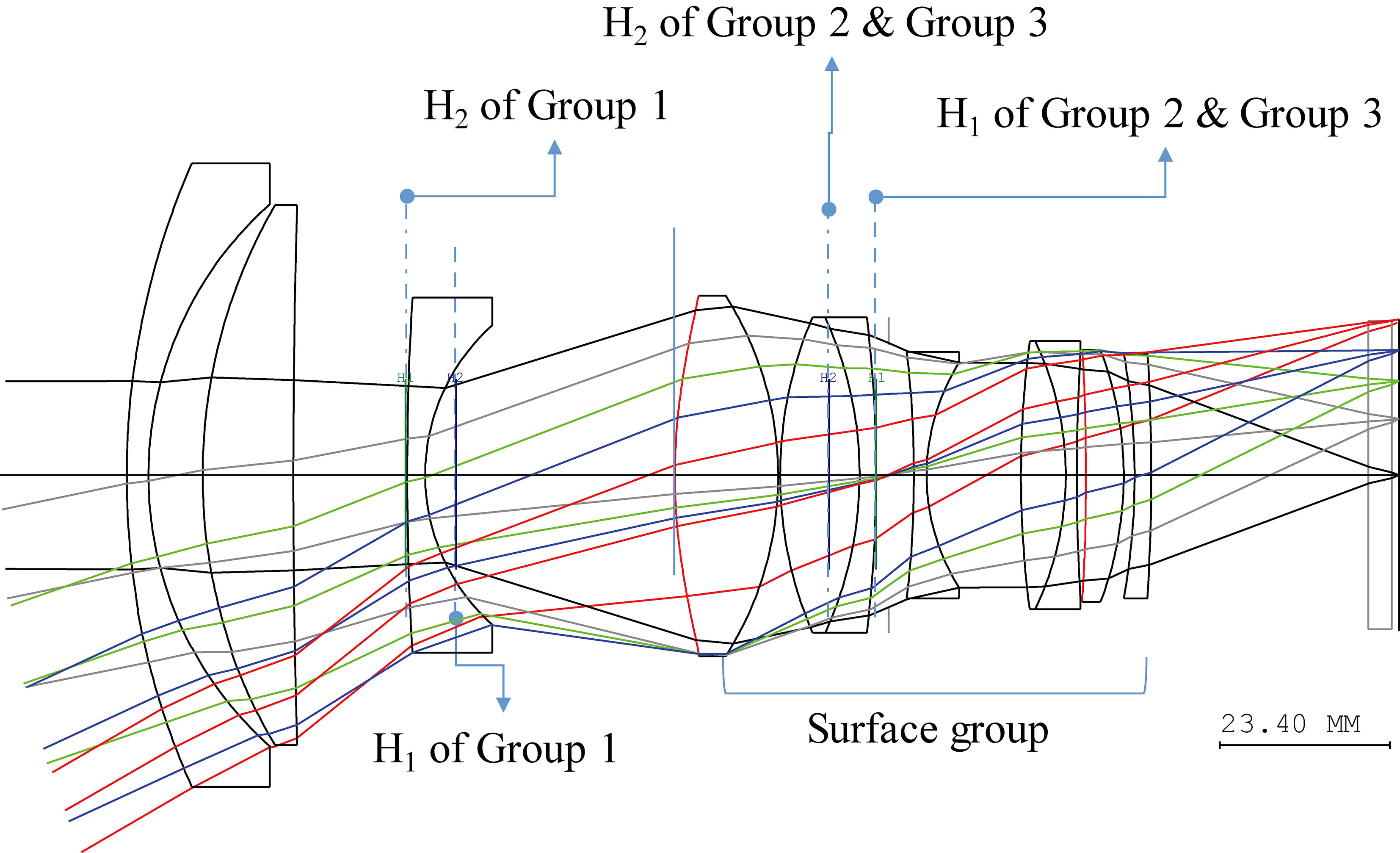
Figure 4.
Lens layout of the composited optical system: FFL, BFL, and EFL (a) before correction and (b) after correction.
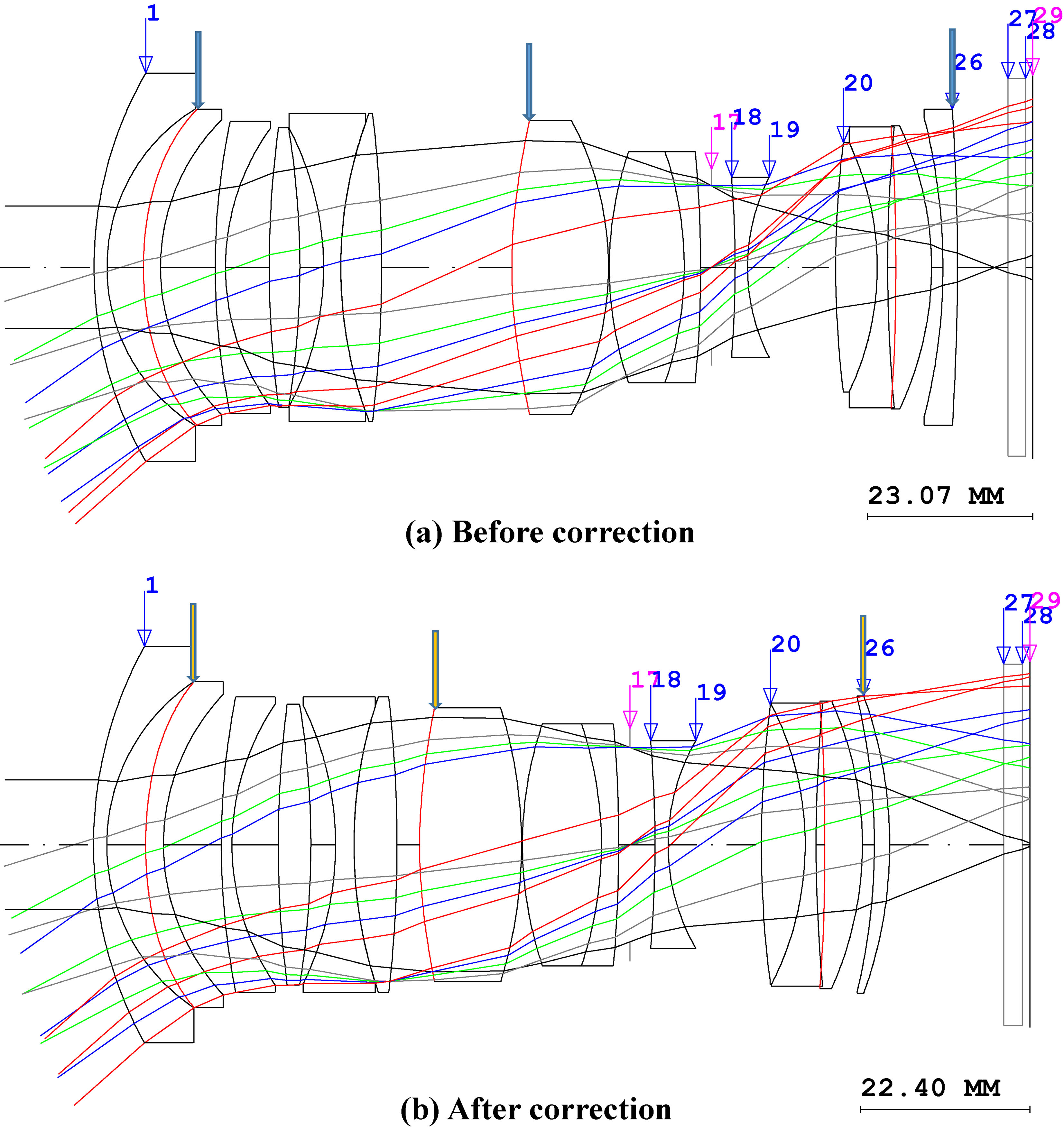
Figure 3 shows the lens layout for Example 1 of patent KR2014-124286 with infinite objectives [23]. For this optical system, only one lens within the optical system is moved, and the system length is not changed during focusing [24]. As shown in Fig. 2, Group 1 is fixed during focusing, but Groups 2 and 3 are moved towards the object. Although the optical system in Fig. 2 has the same FOV and f-number (F/#) as the optical system that we are attempting to design in this study, it cannot be used for a compact system for ophthalmology and dermatology applications, as described in the Introduction section.
Figure 3, on the other hand, shows an optical system whose overall size is scaled up to match the size of the image sensor of the system in Fig. 2. While the optical system in Fig. 3 is a compact system using one piece of lens, similar to the system that we aim to design, it has a different FOV than the system that we aim to design. Comparing the two systems in Figs 2 and 3 reveals that the effective focal length (EFL) of Groups 2 and 3 in Fig. 2 is almost the same as that of the lens group composed of surface group in Fig. 3. This suggests that the lens group of surface in Fig. 3 can be used in place of Groups 2 and 3 in Fig. 2. Obviously, the focal length of the lens group with the surface in Fig. 3 should be scaled down to 43.503 mm because the overall focal length of the optical system must remain unchanged. Furthermore, the distance between the 2
The advantages of our proposed design are as follow. In conventional optical systems like patent JP2016-012034, two or more lens groups move at the time of focusing. However, only one lens is moved in our optical system. Furthermore, it is also possible to implement a wider FOV than the optical system of patent KR2014-0124286.
Here, even if the optical system shown in Fig. 4a is a compact system for ophthalmology and dermatology applications, its back focal length (BFL) is too short, and there is a large distance between the 11
(1)
(2)
(3)
Here,
To obtain the desirable EFL, BFL, and FFL using Eqs (1)–(3), three variables should be adjusted. For example, the curvatures of three surfaces and distances or thicknesses of three surfaces, curvatures of two surfaces and distance or thickness of one surface, and curvature of one surface and distances or thicknesses of two surfaces can be changed to obtain a desirable EFL, BFL, and FFL, respectively. We changed the curvature of surfaces No. 3, 12, and 26 to obtain an EFL of 24.6 mm and an FFL of 20.2 mm, which increased the distance between surface No. 26 and the image surface to 8 mm. The lens layout of the resulting optical system is shown in Fig. 1b. The curvature, thickness, and material of the system shown in Fig. 1a and b are presented in Fig. 2.
The system in Fig. 4a is a composite optical system of Group 1 (from surface No. 1 to surface No. 11) in Fig. 2 and Groups 2 and 3 in Fig. 3. Figure 4b shows an optical system with the same EFL and FFL and a BFL 8 mm greater than that for Fig. 4a, obtained using Eqs (1)–(3).
Figure 5.
Optical data for the composite optical system obtained (a) before and (b) after correcting the FFL, BFL, and EFL.
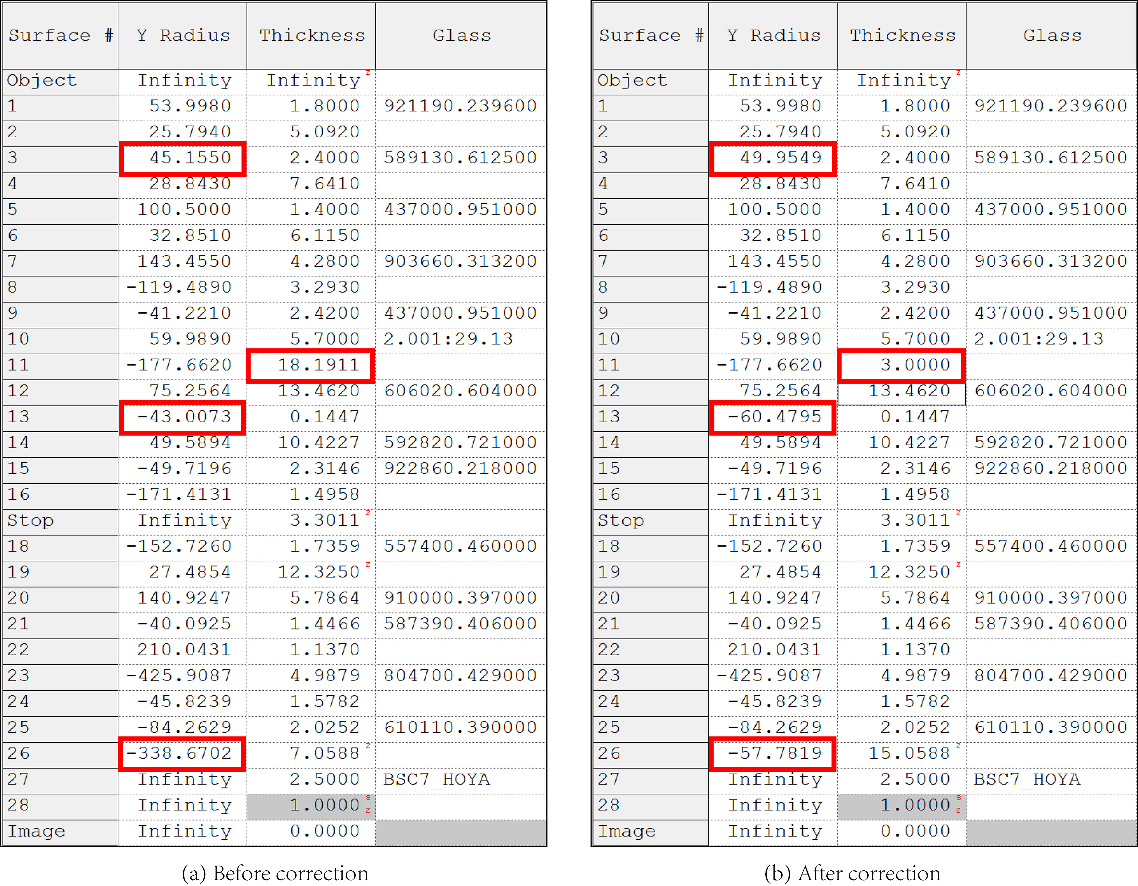
Figure 6.
Spot diagram of the composited optical system: (a) FFL, BFL, and EFL (a) before and (b) after correction.
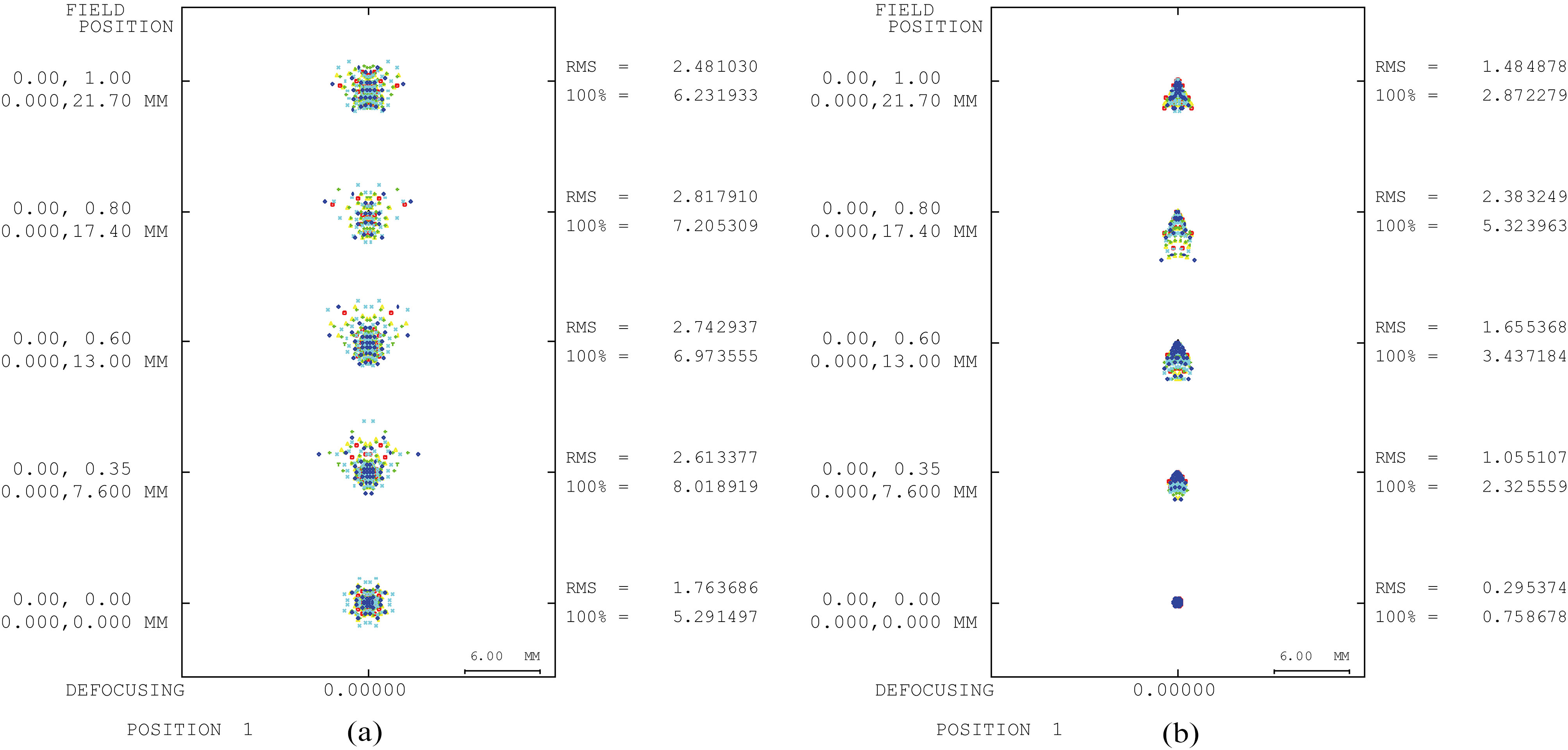
Figure 5 shows the obtained optical data of the composite optical system obtained before and after correcting the FFL, BFL, and EFL specifications. A total of three aspheric lenses were used in the design: 1 piece of lens for No. 10 and 1 piece for each No. 2 and No. 14. A total of 14 lens pieces, including two pieces of extra-low dispersion were employed. The aspheric lenses were used to correct the spherical aberration during the basic design process and were used at the object and image plane, where the maximum height of the chief ray was achieved within the optical system to correct the residual aberration, such as coma aberration and lateral color.
Figure 7.
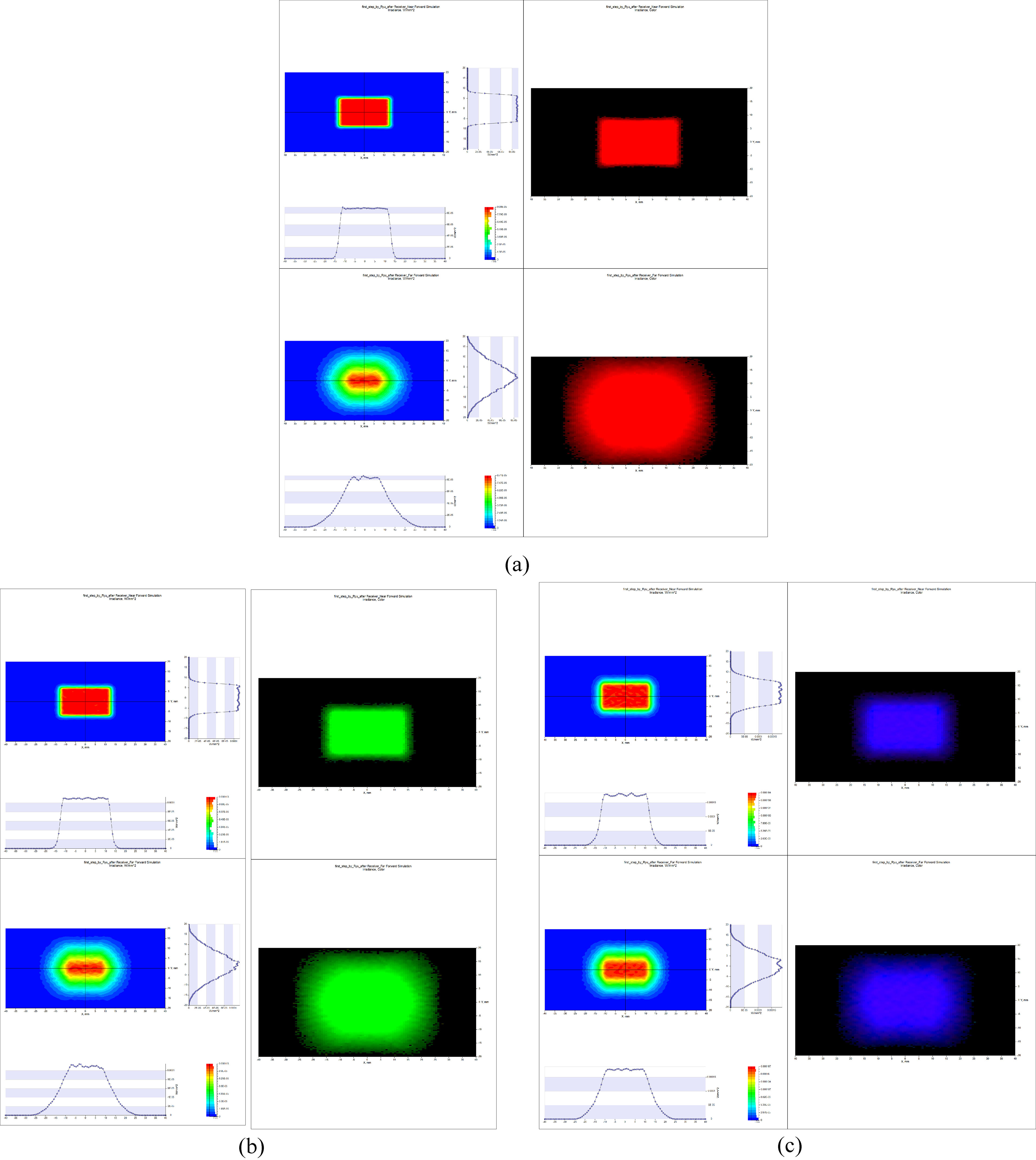
Light-intensity (left) and distribution (right) profiles for (a) red, (b) green, and (c) blue LEDs.
3.Results and discussion
Figure 6 presents graphs showing spot diagrams for two composite optical systems before and after correction of the FFL, BFL, and EFL specifications. The spot sizes are apparently smaller after the correction of the FFL, BFL, and EFL. Although a small amount of coma aberration remains, there are no significant problems, because the purpose of using the optical system is to provide the desired illumination to the sample.
This designed optical system can focus from infinity to a magnification of
The peak wavelengths of the red, green, and blue LEDs (CBT120, Luminus Devices, Sunnyvale, CA, USA) of our designed optical system are 625 nm, 530 nm, and 459 nm, respectively. The full width at half maximum (FWHM) values of the red, green, and blue LEDs were obtained as 16 mm, 35 mm, and 22 mm, respectively. The acquired powers of the red, green, and blue LEDs were 0.29 W, 0.36 W, and 0.60 W, respectively as the efficiency of LEDs depends on the emitted wavelength. The summarized results are provided in Table 1.
Table 1
Summarized results of the designed optical system
| LED | Red | Green | Blue |
|---|---|---|---|
| FWHM (mm) | 16 | 35 | 22 |
| Power (W) | 0.29 | 0.36 | 0.60 |
4.Conclusion
We designed a new ultrawide-angle optical system for ophthalmology and dermatology applications to cover areas of the eye and facial areas near the eye, as conventional optical systems such as optical coherent tomography and slit-lamp bio-microscopy systems have a limited FOV. To achieve a compact and convenient optical system for physicians in related fields, LED lights are used as transmit sources. However, LEDs are non-coherent and divergent transmit sources, and optical systems must be able to steer and focus the light on the desired target positions. Therefore, our designed ultrawide-angle optical systems using LED light sources must cover near-infrared and visible wavelengths between 400 and 700 nm while satisfying the several requirements of the EFL, BFL, and FFL.
To achieve a compact and convenient optical system for such applications, a contrast AF method was used, and weight reduction of the AF group must be considered during the design process to realize a high AF speed. For this reason, we designed a new optical system. Two optical systems that partially satisfy the design specification were composited for an initial design. Then, the Gaussian-bracket method was used to adjust curvatures and the distance between lenses so that the EFL, BFL, and FFL satisfied the desired design goal. The final design of the optical system yielded satisfactory performances.
It was confirmed that the width of the intensity distribution can be easily adjusted according to the movement of the AF lens in our designed optical system. The designed optical system can focus from infinity to a magnification of
The FWHM values of the red, green, and blue LEDs were 16 mm, 35 mm, and 22 mm, respectively. The acquired peak powers of the red, green, and blue LEDs were 0.29 W, 0.36 W, and 0.6 W, respectively when 625 nm, 530 nm, and 459 nm peak wavelengths of the LEDs were used. This design of high illumination intensity is expected to satisfy the demand for interchangeable lens products in compact optical systems that are suitable for use in high-performance ophthalmology and dermatology instruments.
In this study, although we have designed a compact and convenient ultrawide-angle optical system with reduced weight for ophthalmology and dermatology applications, and we expect that a similar method can be applied to various wide-angle optical systems.
Acknowledgments
This research was supported by the Basic Science Research Program through the National Research Foundation of Korea (NRF) funded by the Ministry of Science, ICT and Future Planning (No. NRF-2017R1C1B1003606), the Ministry of Education (No. NRF-2017R1D1A3B03029119), and the Korea Health Technology R&D Project through the Korea Health Industry Development Institute (KHIDI), funded by the Ministry of Health and Welfare, Republic of Korea (HI17C0654).
Conflict of interest
None to report.
References
[1] | Pedrotti FL, Pedrotti LS. Introduction to optics. 2nd ed. Englewood Cliffs, N.J.: Prentice Hall; (1993) . |
[2] | Born M, Wolf E. Principles of optics: electromagnetic theory of propagation, interference and diffraction of light. 7th expanded ed. Cambridge; New York: Cambridge University Press; (1999) . |
[3] | Wang LV, Wu H-I. Biomedical optics: principles and imaging. Hoboken, N.J.: Wiley-Interscience; (2007) . |
[4] | Shung KK, Smith MB, Tsui BMW. Principles of medical imaging. San Diego: Academic Press; (2012) . |
[5] | Liu X, Liu T, Wen R, Li Y, Puliafito CA, Zhang HF, et al. Optical coherence photoacoustic microscopy for in vivo multimodal retinal imaging. Optics Letters. (2015) Apr 1; 40: (7): 1370-3. |
[6] | Sharma KK. Optics: principles and applications. Amsterdam; Boston: Academic Press; (2006) . |
[7] | Smith WJ. Modern optical engineering: the design of optical systems. 4th ed. New York: McGraw Hill; (2008) . |
[8] | Hecht E, Zajac A. Optics. 2nd ed. Reading, Mass.: Addison-Wesley Pub. Co.; (1987) . |
[9] | Whelan HT, Smits RL, Jr., Buchman EV, Whelan NT, Turner SG, Margolis DA, et al. Effect of NASA light-emitting diode irradiation on wound healing. Journal of Clinical Laser Medicine & Surgery. (2001) Dec; 19: (6): 305-14. |
[10] | Schubert EF, Gessmann T, Kim JK. Light emitting diodes. Wiley Online Library, Hoboken; (2005) . |
[11] | Drexler W, Fujimoto JG. Optical coherence tomography: technology and applications. Berlin: Springer; (2008) . |
[12] | Fodor L, Ullmann Y, Elman M. Aesthetic applications of intense pulsed light. London: Springer; (2011) . |
[13] | Sardar DK, Yust BG, Barrera FJ, Mimun LC, Tsin AT. Optical absorption and scattering of bovine cornea, lens and retina in the visible region. Lasers in Medical Science. (2009) Nov; 24: (6): 839-47. |
[14] | Beard P. Biomedical photoacoustic imaging. Interface Focus. (2011) Aug 6; 1: (4): 602-31. |
[15] | Jacques SL. Optical properties of biological tissues: a review. Physics in Medicine and Biology. (2013) Jun 7; 58: (11): R37-61. |
[16] | Wang LV. Photoacoustic imaging and spectroscopy. Boca Raton: CRC; (2009) . |
[17] | Welford WT. Aberrations of optical systems. Bristol; Boston: A. Hilger; (1986) . |
[18] | Walker BH. Optical design for visual systems. Bellingham, Wash.: SPIE Press; (2000) . |
[19] | Kidger MJ. Intermediate optical design. Bellingham, Wash.: SPIE Optical Engineering Press; (2004) . |
[20] | Malacara-Hernández D, Malacara-Hernández Z. Handbook of optical design. 3rd ed. Boca Raton, FL: CRC Press, Taylor & Francis; (2013) . |
[21] | Ryo S. Optical System, Japan; Patent 2014-133470A, (2014) . |
[22] | Laikin M. Lens design. 4th ed. Boca Raton, FL: CRC Press; (2007) . |
[23] | Yoneyama S. Wide angle lens system and photographing apparatus having the same, South Korea, Patent KR10-2014-0124286A, (2014) . |
[24] | Park SC, Lee WS. Paraxial design method based on an analytic calculation and its application to a three-group inner-focus zoom system. Journal of the Korean Physical Society. (2014) Jun; 64: (11): 1671-1676. |
[25] | Herzberger M. Modern geometrical optics. New York,: Interscience Publishers; (1958) . |
[26] | Jung JH, Jung H, Lee SS. Paraxial lens design by using gaussian bracket and method of adjustment for the focal, back focal and front focal length, New Physics (Sae Mulli). (1987) , 27: : 576-582. |


