
Force control of wire driving lower limb rehabilitation robot
Abstract
BACKGROUND:
To solve the technical problems associated with the research on lower limb rehabilitation robot in terms of configuration design, human-machine compatibility, lightweight, and multimodel rehabilitation.
OBJECTIVE:
This study introduced a parallel wire driving lower limb rehabilitation robot. The robot featured modular design, reconfiguration, multimodel, and good human-machine compatibility.
METHODS:
The dynamics model of the wire driving module (WDM) was built based on which a multiple feedback loop controller (including a forward controller and a surplus force compensator) was designed.
RESULTS:
The experimental results showed that the WDM could load force accurately and reliably during the loading procedure.
CONCLUSIONS:
The machinery and control system of the WDM met the design request.
1.Introduction
In terms of the configuration of the robot, the lower limb rehabilitation robots can be divided into the exoskeleton-type and the footpad-type rehabilitation robots [1]. The exoskeleton-type rehabilitation robot drives the coordinated swinging of the legs of the patients, thereby assisting the patients to complete the rehabilitation exercise using the exoskeleton. Different gait training patterns can be realized by changing the movement patterns or the control strategies of the exoskeleton. The most typical exoskeleton-type product is Lokomat [2]. When patients can do some moderate active exercises, the exoskeleton becomes an assistance system, such as the Hybrid Assistive Limb of Tsukuba University and the ReWalk of Argo Medical Technologies [3, 4]. The footpad-type rehabilitation robot, using pedals to drive the patient’s feet, can simulate the natural walking motion of the feet. These kinds of robots can achieve different forms of gait training through controlling the pedals’ attitude and motion. Stefan Hesse, who has been working on the footpad-type rehabilitation robot, has developed the production prototype G-EO System after the prototypes Gait Trainer and Haptic Walker [5]. Through optimization and improving the ordinary elliptical trainer, the research groups from the University of Nebraska-Lincoln and Madonna Rehabilitation Hospital developed an Intelligently Controlled Assistive Rehabilitation Elliptical trainer [6].
Presently, the research on the lower limb rehabilitation robots is associated with the following problems: (1) The existing exoskeleton-type rehabilitation robots have some disadvantages such as low stiffness, low precision, large inertia, and poor real-time capability. (2) It is difficult to implement single-joint training by using the footpad-type rehabilitation robot. (3) The DOF of the existing lower limb rehabilitation robot is limited, leading to movement deviation between the human body and the robot. The design of the robot needs to address problems pertaining to human-machine compatibility. (4) The drive system of the robot is required to work against the gravity of the mechanical body and the patient, resulting in high energy consumption and complex structure. It is necessary to carry out the lightweight design to improve the working efficiency. (5) The lower limbs are required to perform complex force/pose training in different rehabilitation phases. Most of the existing robots can realize pose control, but few robots can realize the complex force control.
In the wire driving mechanism, the wire replaces the rigid element as the transmission component. The wire driving mechanism has high load/weight ratio, high velocity/accuracy ratio, large working space, and adjustable stiffness. The wire driving robot has unique comprehensive advantages compared with traditional serial robots and parallel robots [7]. The application of wire driving mechanism in rehabilitation represents bright prospects because of the good flexibility. Some typical robots are available, such as MariBot, CAREX, C-ALEX, ROPES, PACER, and String Man [8, 9, 10, 11, 12, 13, 14, 15].
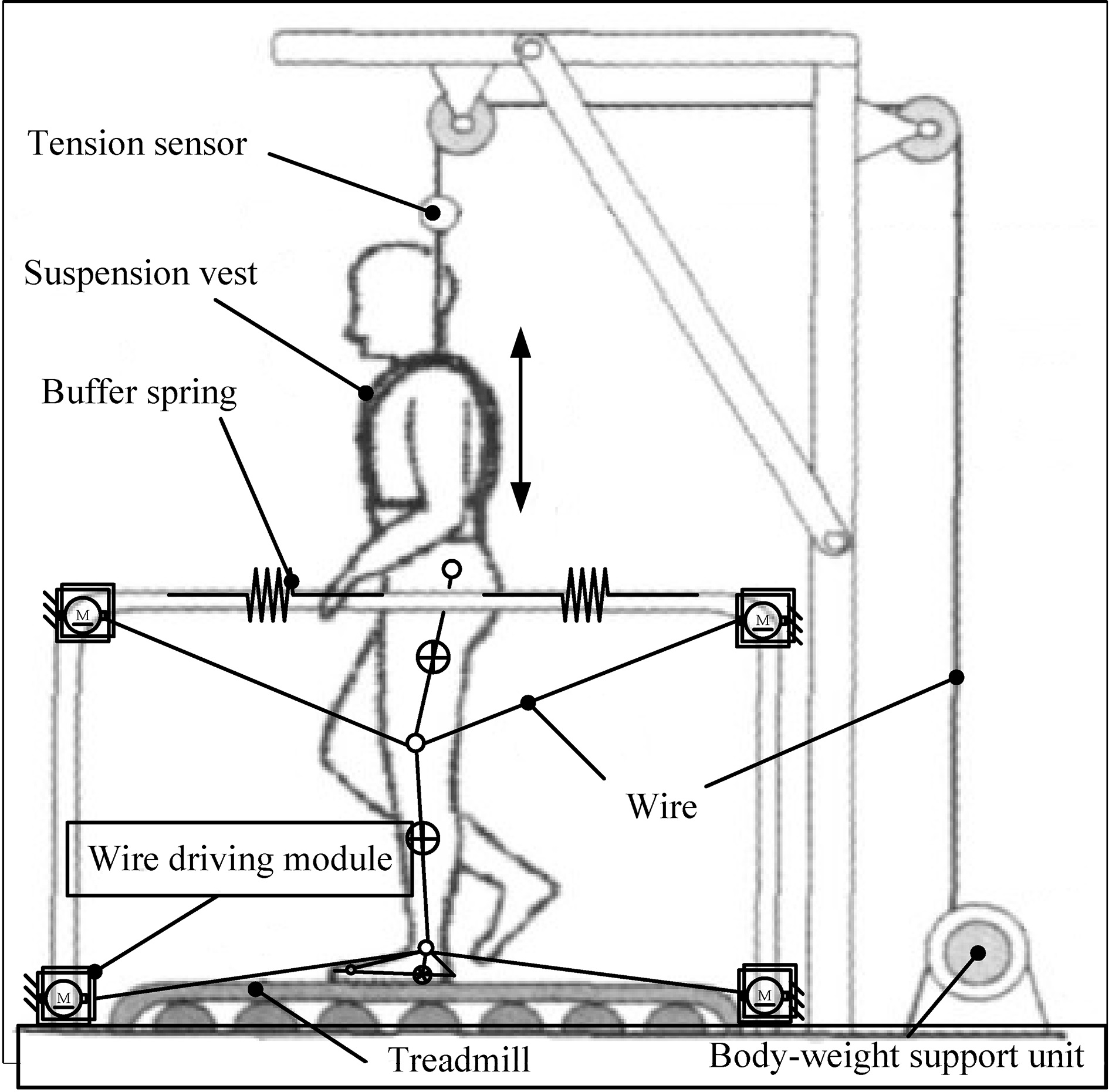
In this study, a parallel wire driving robot (PWDR) was used to realize the rehabilitation of lower limbs, featuring modular design, reconfiguration, multimodel, and good human-machine compatibility. Figure 1 illustrates the structural scheme of the wire driving lower limb rehabilitation robot. The whole rehabilitation system was built on a treadmill. Four wire driving module (WDM) made up a planar PWDR. The robot could realize comprehensive rehabilitations, including passive rehabilitation, assistive rehabilitation, and initiative rehabilitation, by controlling the pose and force of the shank. The body-weight support unit was used to control the force that is applied on the lower limbs. The buffer springs were adopted to limit the motion of the pelvis of the subject. The pelvis of the subject could move freely within limits.
Figure 1.
Structural scheme of the wire driving lower limb rehabilitation robot.
In the passive training process, the WDM took the initiative to drive the shank in accordance with the natural motion. The WDM was a position servo system. The gravity of the lower limb and the joint resistances were the external disturbances that had some effect on the position servo system. The WDM could achieve high position accuracy easily. In the active training process, the WDMs passively followed the active movement of lower limbs and exerted a desired resultant force on the shank. For each WDM, it was a force servo system, or rather a typical passive force servo system [16]. The motion of the lower limbs had great influence on the control accuracy of the passive force servo system. The major problem in researching the passive loading system lay in designing the forward force controller and the surplus force compensator.
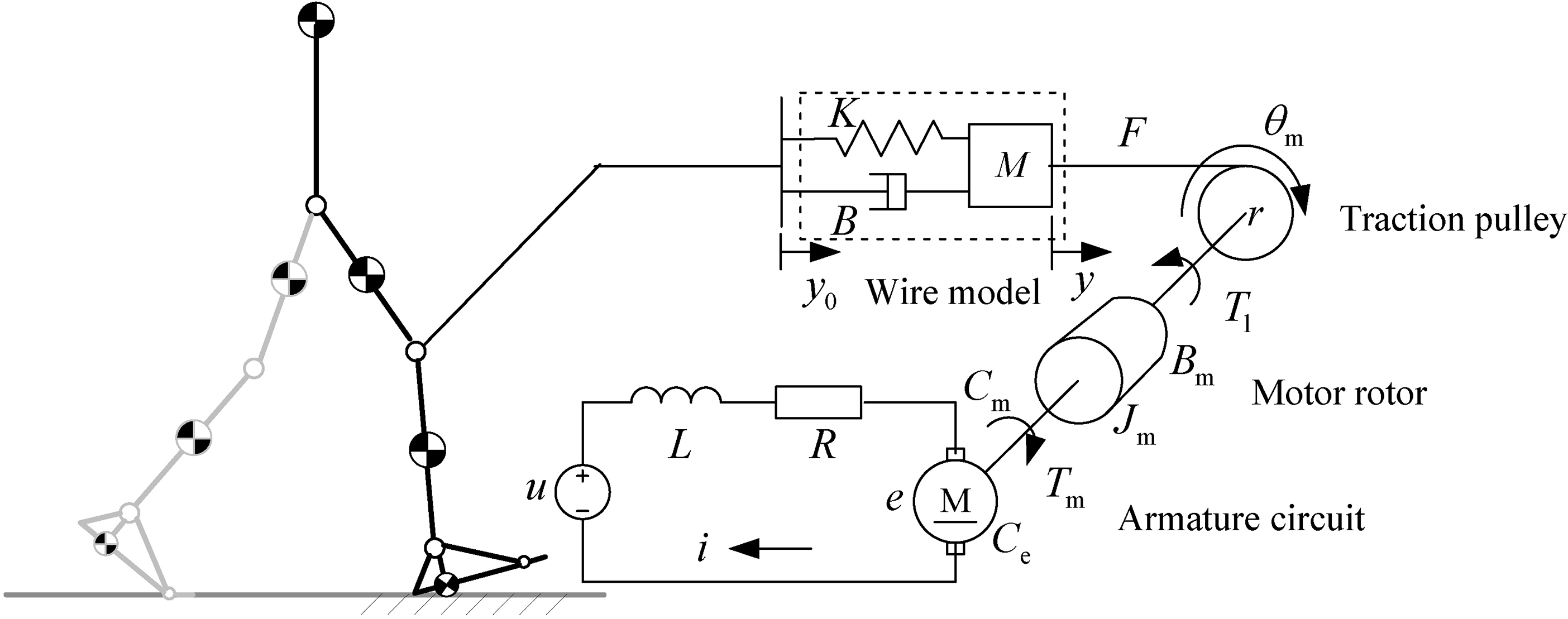
2.Mechanical construction and dynamics modeling
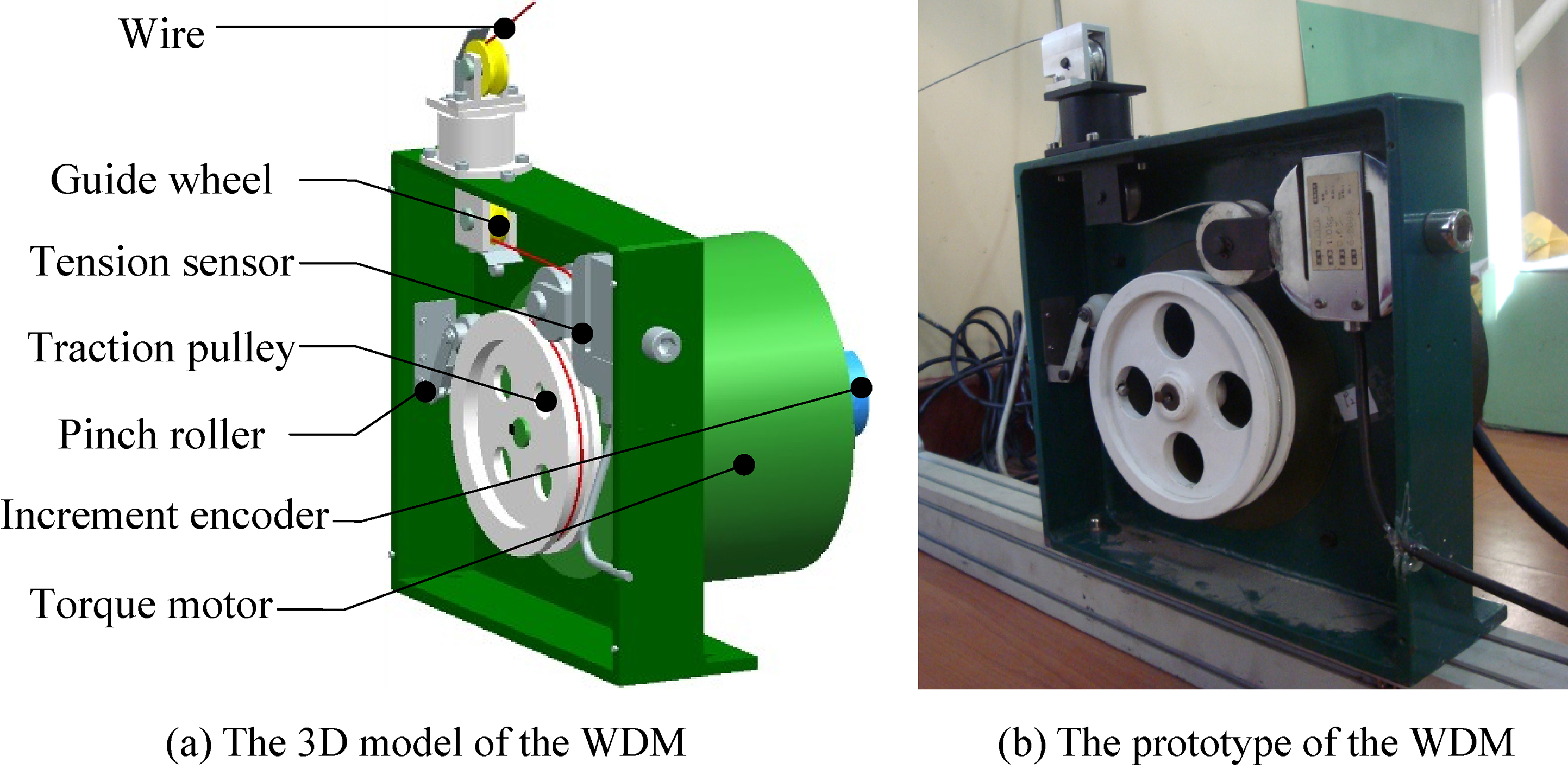
2.1Mechanical construction of the WDM
Figure 2 illustrates the composition of the WDM. The WDM consisted of a torque motor that drove a traction pulley directly. An increment encoder was located on the motor, and the encoder’s readings were used to determine the wire elongation. The pose state and localization of the lower limbs could be further determined. A pinch roller, fixed on the side frame, served to confine the wire to the traction pulley groove. A tension sensor was fixed on the other side of the frame, and a guide wheel was located on the opposite part of the tension sensor. After passing through the guide wheel, the wire’s motion direction changed by 180
Figure 2.
Composition of the WDM.
2.2Wire driving dynamics model
On the basis of the mechanical construction, the mechanism model of the WDM is shown in Fig. 3. The WDM loaded the tension on the lower limbs through the wire. The wire was simplified into a mass-spring-damping model for its low vibration frequency in the training process to clarify the effect of the wire more clearly.
Figure 3.
Mechanism model of the WDM.
The block diagram of the WDM is shown in Fig. 4. The output
Figure 4.
Block diagram of the WDM.

Based on Fig. 4, the wire driving dynamics model of the WDM was as follows:
(1)
where
(2)
(3)
In Eqs (2) and (3),
The nominal value of each parameter in the WDM dynamics model is shown in Table 1.
Table 1
Parameters of the wire driving dynamics model
| Parameter | Value | Parameter | Value |
|---|---|---|---|
|
| 5 | 0.027 | |
| 0.008 | 0.060 | ||
| 3.82 | 0.036 | ||
| 3.15 | 1 | ||
| 0.0106 | 30 |
2.3Characteristic analysis
The frequency characteristic of
Figure 5.
Bode diagram of M
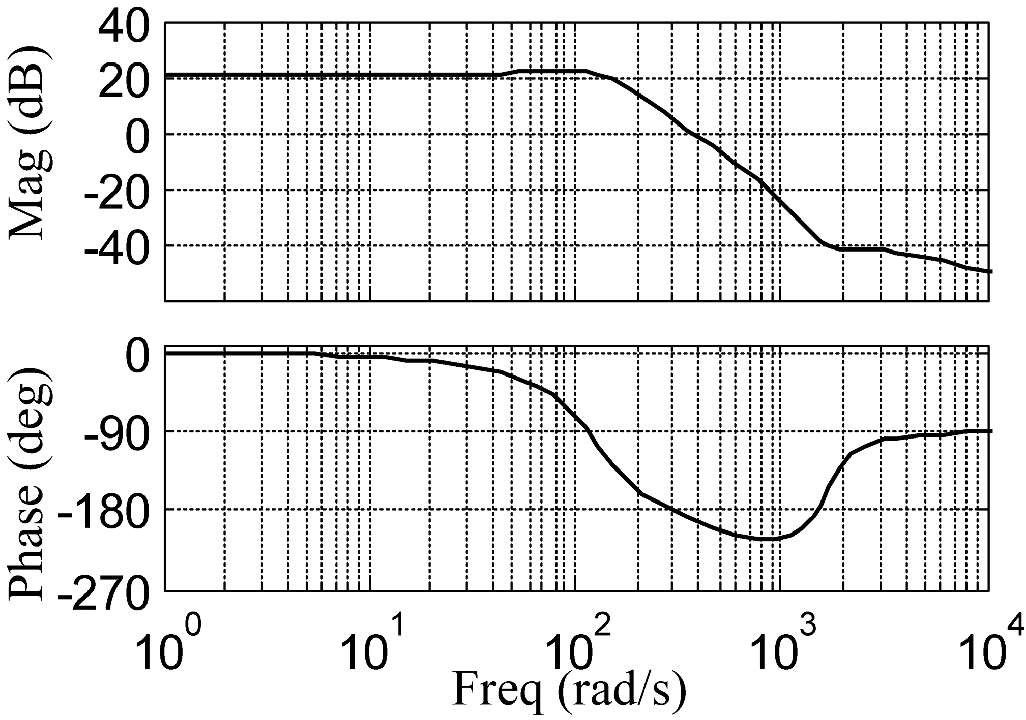
Figure 6.
Bode diagram of M
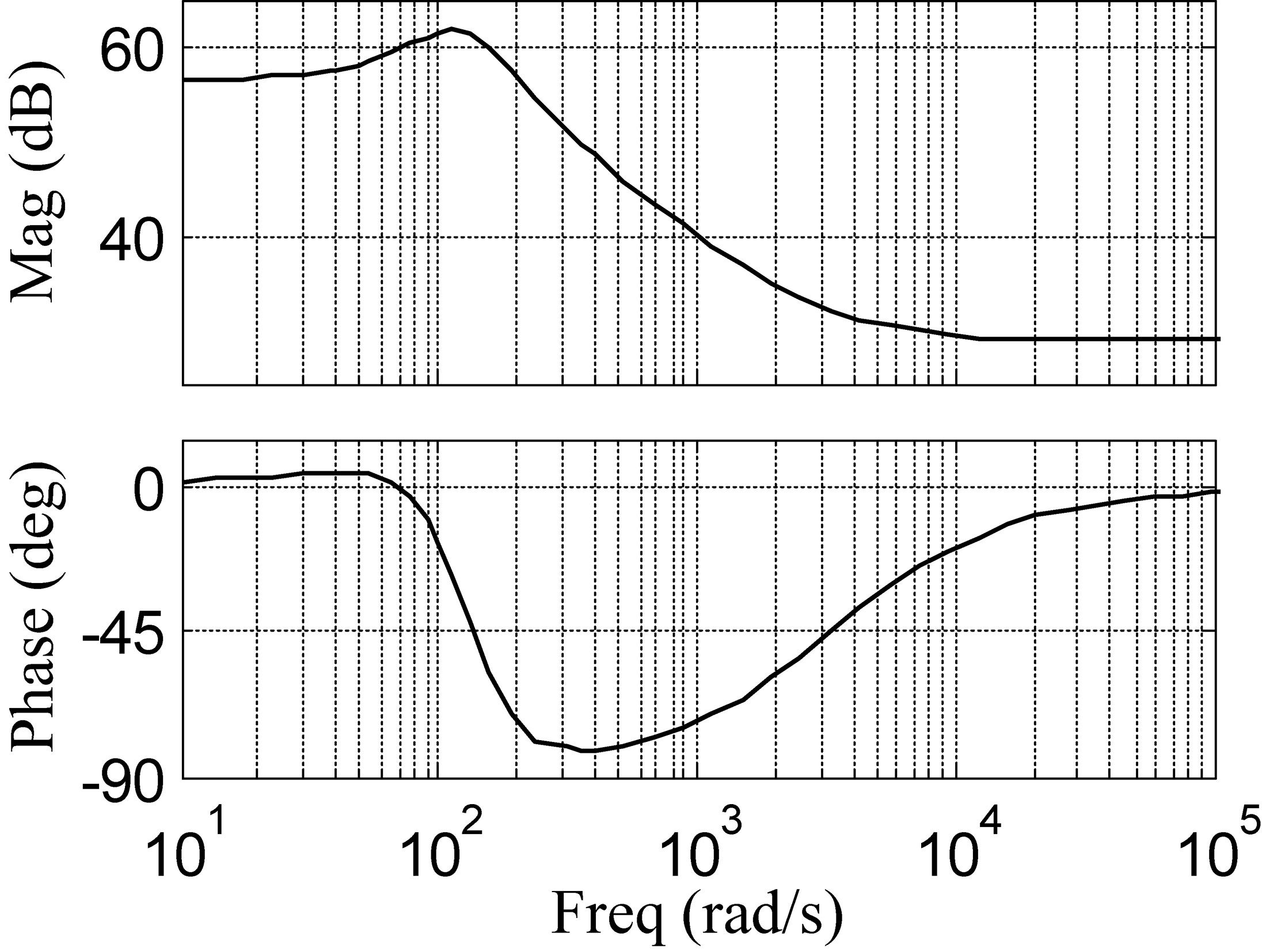
The Bode diagram of
The surplus force could not be completely eliminated due to the following reasons: (1) The surplus force caused by the motion of the lower limb affected the output directly. However, the compensation, generated by the controller, always lagged behind the output. (2) The change in the work environment resulted in the variation in the dynamics model of WDM for the nonlinearity and time variation of the system, which made it difficult to design the surplus force compensator.
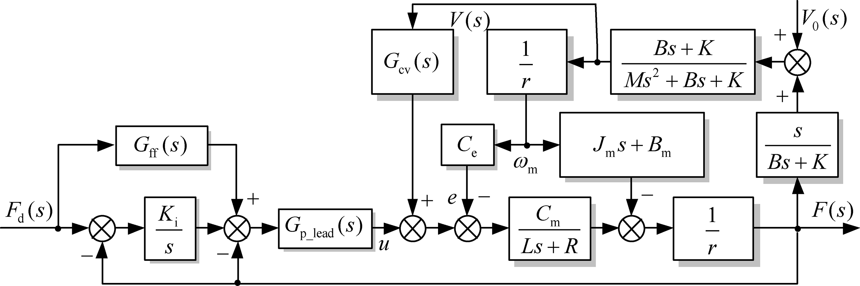
Figure 7.
Multiple feedback loop force control strategy for the wire driving system.
It is demanded that the surplus force reduction rate
(4)
In Eq. (4),
3.Control strategy
The multiple feedback loop force control strategy for the wire driving passive force servo system is shown in Fig. 7.
The control strategy design for the passive force servo system should consider two aspects: (a) A forward controller should be designed based on the forward channel transfer function
An integral element was adopted as the primary control element for
In this case, a local negative feedback element
(5)
Under the premise of ensuring stability, the feed-forward element
With reference to the block diagram of the WDM in Fig. 4 and Eq. (1), the surplus force was generated by the input velocity disturbance
(6)
Actually, the velocity of the traction point
(7)
Figure 8.
Experimental platform of the multiple feedback loop control for passive loading.
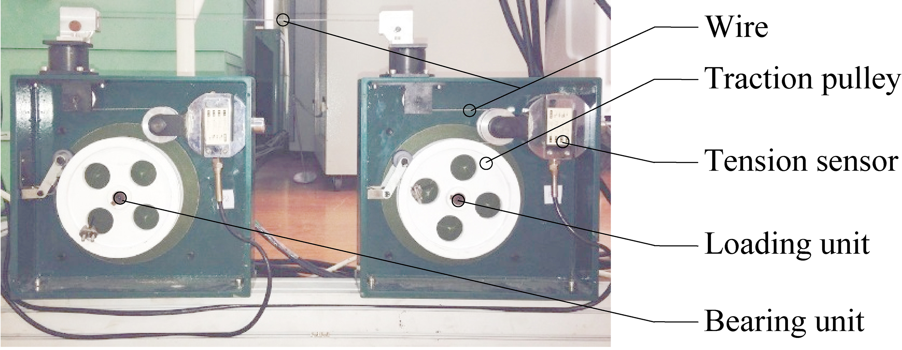
Figure 9.
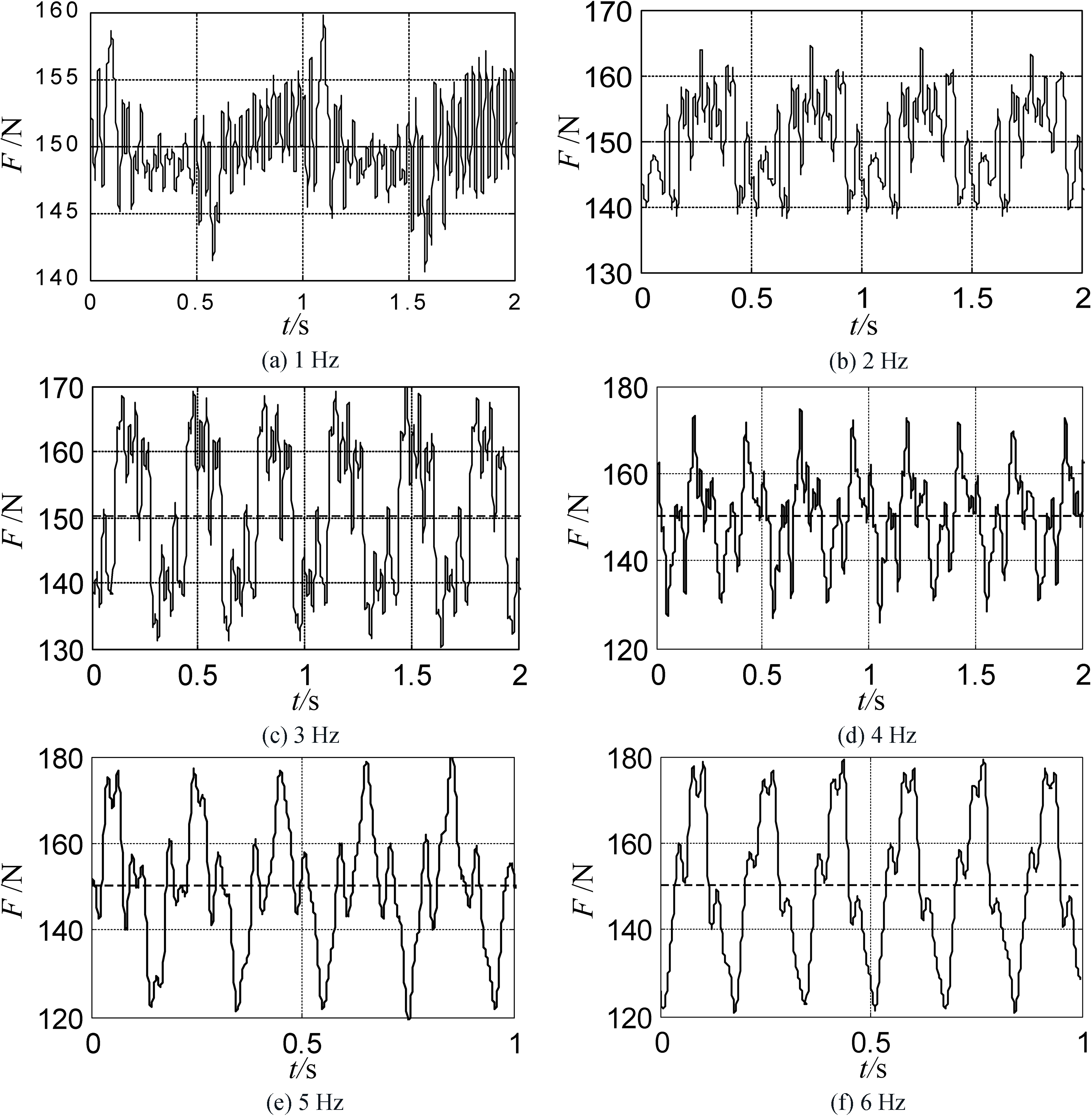
Surplus force of the wire driving module with different frequency velocity disturbance input.
4.Experimental evaluation
Passive loading experiment was performed in this section to further confirm the effectiveness of the multiple feedback loop force controller. The experimental platform is shown in Fig. 8. The bearing unit was a position servo system. The loading unit, following the bearing unit passively and exerting a force on the bearing unit, was a force servo system.
With reference to the multiple feedback loop force control strategy in Fig. 7, the wire tension
Table 2
Statistical results of the multiple feedback loop control for passive loading
| Velocity frequency, Hz | 1 | 2 | 3 | 4 | 5 | 6 |
| Velocity amplitude, m | 0.3 | |||||
| Surplus force before compensation, N | 202.14 | 204.24 | 207.54 | 212.64 | 218.58 | 226.01 |
| Surplus force after compensation, N | 10 | 14 | 19 | 23 | 28 | 29 |
| Surplus force reduction rate, | 95.05 | 93.15 | 90.85 | 89.18 | 87.19 | 87.17 |
The theoretical surplus force compensator was simplified based on the dominant pole placement to facilitate implementation of the experiments. The experiments results indicated that the multiple feedback loop force controller could decrease the surplus force efficiently and improve the precision. The designed controller could meet the performance requirements of lower limb rehabilitation.
5.Conclusions and future work
This study presented the mechanical design of the WDM and experimental evaluation of a wire driving lower limb rehabilitation robot. The dynamics model of the WDM was provided, based on which a forward controller and a surplus force compensator for WDM were designed. The experiments demonstrated that the WDM could load force accurately and reliably during the loading procedure. The machinery and control system of the WDM achieved the design request.
Future work will focus on control methodologies for the robot to improve the force control accuracy. Further experimental and clinical studies will be conducted to determine the efficacy and safe applicability of the robot in human subjects.
Acknowledgments
This project is supported by National Natural Science Foundation of China (Grant No. 51705534), Fundamental Research Funds for the Central Universities No. 18CX02085A and Shandong Provincial Natural Science Foundation No. ZR2016EEB12.
Conflict of interest
None to report.
References
[1] | Meng W, Liu Q, Zhou Z, et al. Recent development of mechanisms and control strategies for robot-assisted lower limb rehabilitation. Mechatronics, (2015) ; 31: : 132-145. |
[2] | Kumru H, Murillo N, BenitoPenalva J, et al. Transcranial direct current stimulation is not effective in the motor strength and gait recovery following motor incomplete spinal cord injury during Lokomat® gait training. Neuroscience letters, (2016) ; 620: : 143-147. |
[3] | Wall A, Borg J, Palmcrantz S. Clinical application of the Hybrid Assistive Limb (HAL) for gait training – a systematic review. Frontiers in systems neuroscience, (2015) ; 9. |
[4] | Esquenazi A, Talaty M, Packel A, et al., The ReWalk powered exoskeleton to restore ambulatory function to individuals with thoracic-level motor-complete spinal cord injury. American Journal of Physical Medicine & Rehabilitation, (2012) ; 91: (11): 911-921. |
[5] | Hesse S Waldner A, Tomelleri C. Innovative gait robot for the repetitive practice of floor walking and stair climbing up and down in stroke patients. Journal of NeuroEngineering and Rehabilitation, (2010) ; 7: : 30-40. |
[6] | Winstein CJ, Wolf SL, Dromerick AW, et al. Effect of a task-oriented rehabilitation program on upper extremity recovery following motor stroke: the ICARE randomized clinical trial. Jama, (2016) ; 315: (6): 571-581. |
[7] | Pott A, Bruckmann T. Cable-Driven Parallel Robots. Springer Berlin Heidelberg, (2013) . |
[8] | Trevisani A. Planning of dynamically feasible trajectories for translational, planar, and underconstrained cable-driven robots. Journal of Systems Science and Complexity, (2013) ; 26: (5): 695-717. |
[9] | Mao Y, Jin X, Dutta GG, et al. Human movement training with a cable driven arm exoskeleton (carex). IEEE Transactions on Neural Systems and Rehabilitation Engineering, (2015) ; 23: (1): 84-92. |
[10] | Jin X, Cui X, Agrawal SK. Design of a cable-driven active leg exoskeleton (c-alex) and gait training experiments with human subjects. 2015 IEEE International Conference on Robotics and Automation (ICRA). (2015) ; 5578-5583. |
[11] | Alamdari A, Krovi V. Design and analysis of a cable-driven articulated rehabilitation system for gait training. Journal of Mechanisms and Robotics, (2016) ; 8: (5): 051018. |
[12] | Alamdari A, Krovi V. Parallel articulated-cable exercise robot (PACER): novel home-based cable-driven parallel platform robot for upper limb neuro-rehabilitation. Proceedings of the ASME 2015 International Design Engineering Technical Conferences and Computers in Engineering Conference, August. (2015) ; 2-5. |
[13] | Surdilovic D, Zhang J, Bernhardt R. STRING-MAN: Wire-robot technology for safe, flexible and human-friendly gait rehabilitation. IEEE 10th International Conference on Rehabilitation Robotics. (2007) ; 446-453. |
[14] | Wang KY, Di CB, Tang XQ, et al. Modeling and Simulation to Muscle Strength Training of Lower Limbs Rehabilitation Robots. Advances in Mechanical Engineering, (2014) . |
[15] | Rosati G, Masiero S, Rossi A. On the Use of Cable-Driven Robots in Early Inpatient Stroke Rehabilitation. Advances in Italian Mechanism Science. Springer International Publishing, (2017) ; 551-558. |
[16] | Hirata Y, Shirai R, Kosuge K. Position and orientation control of passive wire-driven motion support system using servo brakes. 2017 IEEE International Conference on Robotics and Automation (ICRA). (2017) ; 3702-3707. |
[17] | Lin X, Zhang R. H (A) Control for Stochastic Systems with Poisson Jumps. Journal of Systems Science & Complexity, (2011) ; 24: (4): 683-700. |
[18] | Li Y, Zhang W, Liu X. Stability of Nonlinear Stochastic Discrete-Time Systems. Journal of Applied Mathematics, (2013) . |


