
Comparative analysis of the stress distribution in five anatomical types of maxillary central incisor
Abstract
BACKGROUND:
The maxillary central incisor is one of the most important anatomical indicators in esthetics, and stress distribution may vary among its five anatomical views (labial, palatal, mesial, distal, and incisal).
OBJECTIVE:
To compare stress distribution among the five anatomical views of the maxillary central incisor under loading force at five angles and to observe and analyze the stress distribution in the dentin and periodontal ligament.
METHODS:
We established three-dimensional finite element models of the five different views, which simulated the bite force with a static load force at 0
RESULTS:
As the angle increased, the equivalent stress on the periodontal ligament, overall tooth displacement, equivalent stress, and displacement over the four views increased. The peaks of equivalent stress over the four views appeared within 0.8–17 mm below the CEJ, although all equivalent stress values decreased while approaching the peak. Within 1–19 mm below the CEJ, the equivalent stress over the M1 and P1 views of the maxillary central incisor decreased substantially.
CONCLUSION:
The peaks of the equivalent stress over the M1 and P1 views of the maxillary central incisor and their stress distribution were lower than those of the other three types. Our findings provided theoretical data on the biomechanics of this esthetically important tooth, which may be useful during implantation of missing maxillary central incisors.
1.Introduction
The maxillary central incisor is one of the most important anatomical indicators in aesthetics, and the study of its stress distribution is a focus in oral biomechanics research. The three-dimensional finite element model is an advanced and effective biomechanical analysis method and has been widely used in the field of oral medicine for many years. Many clinical researchers have applied a variety of finite element analysis software to obtain accurate oral biomechanical parameters, which provided a theoretical basis for the later repair of missing or defected maxillary anterior teeth [1]. However, most of the related studies [2, 3] were focused on the stress distribution of a certain type of tooth under the same loading force, and the analysis of the stress distribution in the tooth was also limited to the stress at a few sites of the tooth, with few investigations into the stress distribution and displacement situation of the overall maxillary central incisor, periodontal ligament, and surrounding alveolar bone under different loading forces.
In this study, a three-dimensional finite element model of the maxillary central incisor was established based on the different anatomical types of Chinese people [4]. The bite force was simulated to compare the similarities and differences in the stress distribution and displacement characteristics of the five anatomical types of maxillary central incisor, with a systematic investigation of the distribution trends, which is expected to provide the biomechanical theoretical basis for later aesthetic repair or therapy.
2.Materials and methods
2.1Modeling materials
Based on the anatomical classification of five different natural maxillary central incisors by Lau [4], five adult female volunteers were selected, approved by the Ethics Committee and informed consent, with the requirements of complete dentition, healthy periodontium, neat dental arrangement, neutral molar relationship, and normal biting status. The maxillary central incisors were complete with no obvious defects and wear, normal size and shape, and the tooth shape in line with the dental standards in Chinese people. X-ray results showed no apical root resorption of the maxillary anterior teeth and normal alveolar bone height. The five volunteers were each classified as one of the five anatomical types.
The test object assumed the supine position, with the chin elevated so that the lower edge of the lower jaw was perpendicular to the horizontal plane; the head was fixed, and a pre-made bite plate was worn; the mouth of the test object was slightly open, to avoid the touching and overlapping of the upper and lower dentition. A spiral CT system (USA GE MEDICAL SYSTEMS / Light Speed VCT) was used to perform horizontal maxillary thin scanning, with the scanning flag line parallel to the lower edge of the mandible. Cross-sectional scanning was performed from the maxillary edge, up to the top of the head, with a thickness of 0.625 mm, a layer growth of 0.625 mm, and a total of 384 layers.
2.2Anatomical classification of the maxillary central incisor
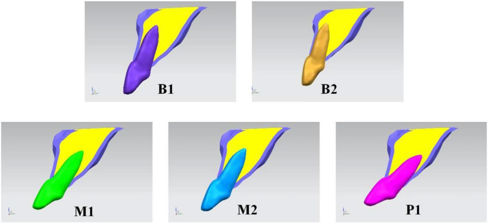
In this study, the statistical classification method by Lau et al. was applied to classify the maxillary central incisors into five common types (B1, B2, M1, M2, and P1), as follows:
B1: The root is near the surface of the labial bone wall, pointing toward the palatal side or parallel to the long axis of the alveolar bone; B2: The root is near the surface of the labial bone wall, pointing toward the buccal side; M1: The root is located at the midline of the labial-palatal bone wall, pointing toward the palatal side or parallel to the long axis of the alveolar bone; M2: The root is located at the midline of the labial-palatal bone wall, pointing toward the buccal side; P1: The root is near the surface of the palatal bone wall (Fig. 1).
Figure 1.
The anatomical classification of the maxillary central incisor.
2.3Establishment of the three-dimensional model
The image data of the CT scan in DICOM format were input in Mimics 15.0 (Mimics, Materialise, Belgium) for three-dimensional model reconstruction. Registration was carried out based on the machine coordinate system of the CT equipment as well as the coronal, sagittal, and horizontal orientations of the software. The mandible and the unnecessary portions of the maxilla in the model were detected using the command of Erase in Edit Masks, thereby obtaining the desired CT image of the maxillary central incisor and the peripheral maxilla. Different image layers were established for different parts of the maxilla to distinguish them. The threshold of the image was adjusted to erase the undesired parts of the image layer by layer. The three-dimensional images of different parts were generated using the Calculate 3D command, to obtain the desired three-dimensional image of the maxilla. The teeth were offset by 0.25 mm as the thickness of periodontal ligament using the Dilate command. The model included the enamel, cementum, dentin, root canal, periodontal ligament, cortical bone, and cancellous bone of the central incisors.
The initial triangular patch models were imported into Geomagic Studio (Geomagic Studio, Raindrop, USA). The defects of the triangular patches were fixed using the command of Grid doctor to remove the sharp edges, small passages, and noise. A solid model for each part of the surface was generated using the surface function.
The establishment of the three-dimensional model was achieved using UG NX (UG NX, Siemens, Germany) software. The established models of the enamel, cementum, dentin, root canal, periodontal ligament, cortical bone, and cancellous bone of the central incisor were imported into UG NX software using the Boolean operation command to generate the relative positional relationship among the maxillary portions.
2.4Establishment of the three-dimensional finite element model
2.4.1Meshing
The obtained three-dimensional solid model was imported into the finite element software ANSYS Workbench 13 (ANSYS, Inc. USA). Finite element meshing was conducted for the enamel, cementum, dentin, root canal, periodontal ligament, cortical bone, and cancellous bone of the central incisor, with the four-node tetrahedral meshing structure.
2.4.2Experimental assumptions and boundary conditions
In this study, the biological materials were assumed to be the linear elastic bodies that were homogeneous, continuous, and isotropic, and the deformation of the materials under force was minor. The parameters of each portion of the material were assigned (elastic modulus, Poisson’s ratio) as shown in Table 1. The contacting surfaces were connected by bonding, without relative sliding. The elastic modulus of each part of the model and Poisson’s ratio were assigned based on the reference values [5].
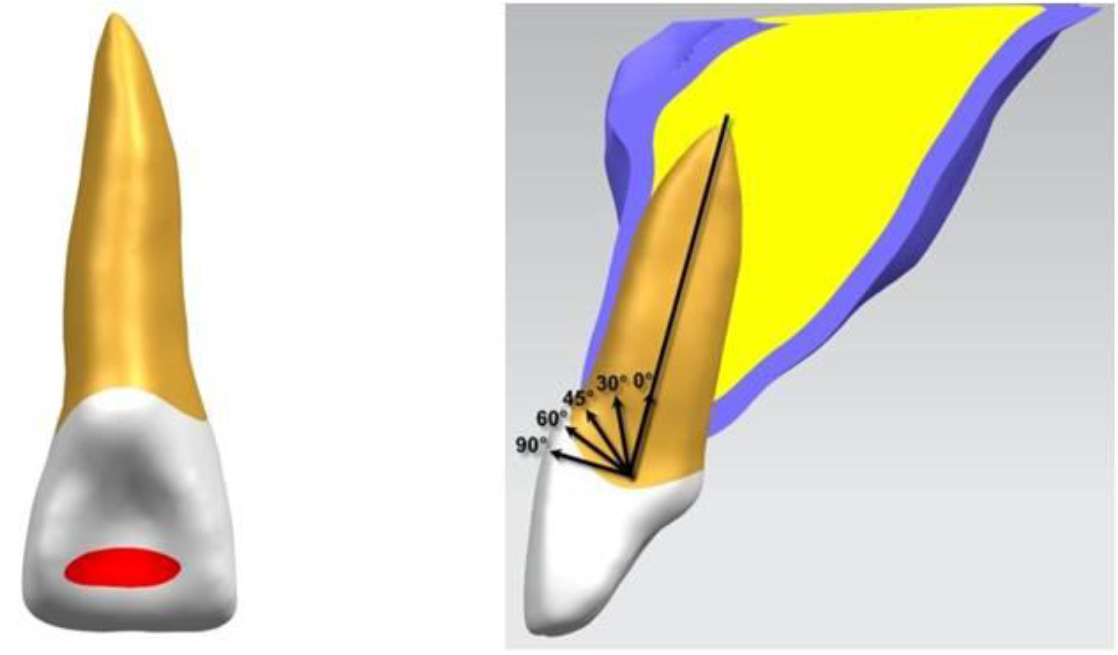
2.5Application approach of the loading stress
The loading stress was applied on the 1/3 junction of the lateral palatal incisor and the lateral palatal midline of the maxillary central incisor (In the middle of incisal 1/3 at palatal surface), in the plane-loading approach, with a stress force of 100 N. The bite force was simulated so that the direction of the loading force and the long axis of the tooth exhibited different angles, including 0
Figure 2.
The location and different angles of the loading stress.
2.6Outcome measures
ANSYS Workbench 13.0 finite element analysis software was used to calculate the models of the five anatomical types of maxillary central incisor and the surrounding alveolar bone. The loading force was applied at different angles to simulate the bite force. In order to analyze the stress distribution of maxillary central incisors, the stress distribution of natural teeth is divided into four sides (the labial, palatal, mesial, and distal sides).
The observed indicators were as follows:
• The equivalent stress at the connecting lines of the labial tooth neck-apex, the palatal tooth neck-apex, the mesial tooth neck-apex, and the distal tooth neck-apex (i.e., the labial, palatal, mesial, and distal lines);
• The displacement situation at the connecting lines of the labial tooth neck-apex, the palatal tooth neck-apex, the mesial tooth neck-apex, and the distal tooth neck-apex (i.e., the labial, palatal, mesial, and distal lines);
• The overall equivalent stress for the periodontal ligament of the maxillary central incisor.
3.Results
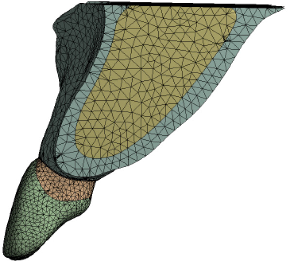
3.1Meshing of the three-dimensional model
With a four-node tetrahedral mesh as a unit, the grid of the three-dimensional finite element model of the maxillary central incisor resulted (Fig. 3). B1: 201367 Nodes, 126774 Elements; B2: 201072 Nodes, 126430 Elements; M1: 200276 Nodes, 126005 Elements; M2: 199568 Nodes, 125519 Elements; P1: 198427 Nodes, 124666 Elements. In total, five models were obtained.
Figure 3.
Mesh.
3.2Stress analysis for the four lines of maxillary central incisor
The vertical ordinate of the line graph (Fig. 5) is the stress value (unit: MPa), and the horizontal ordinate is the distance between the dental cervix to the root tip (unit: mm).
Figure 4.
Stress analysis for the four lines of maxillary central incisor. A: lingual line; B: palatal line; C: mesial line; D: distal line.
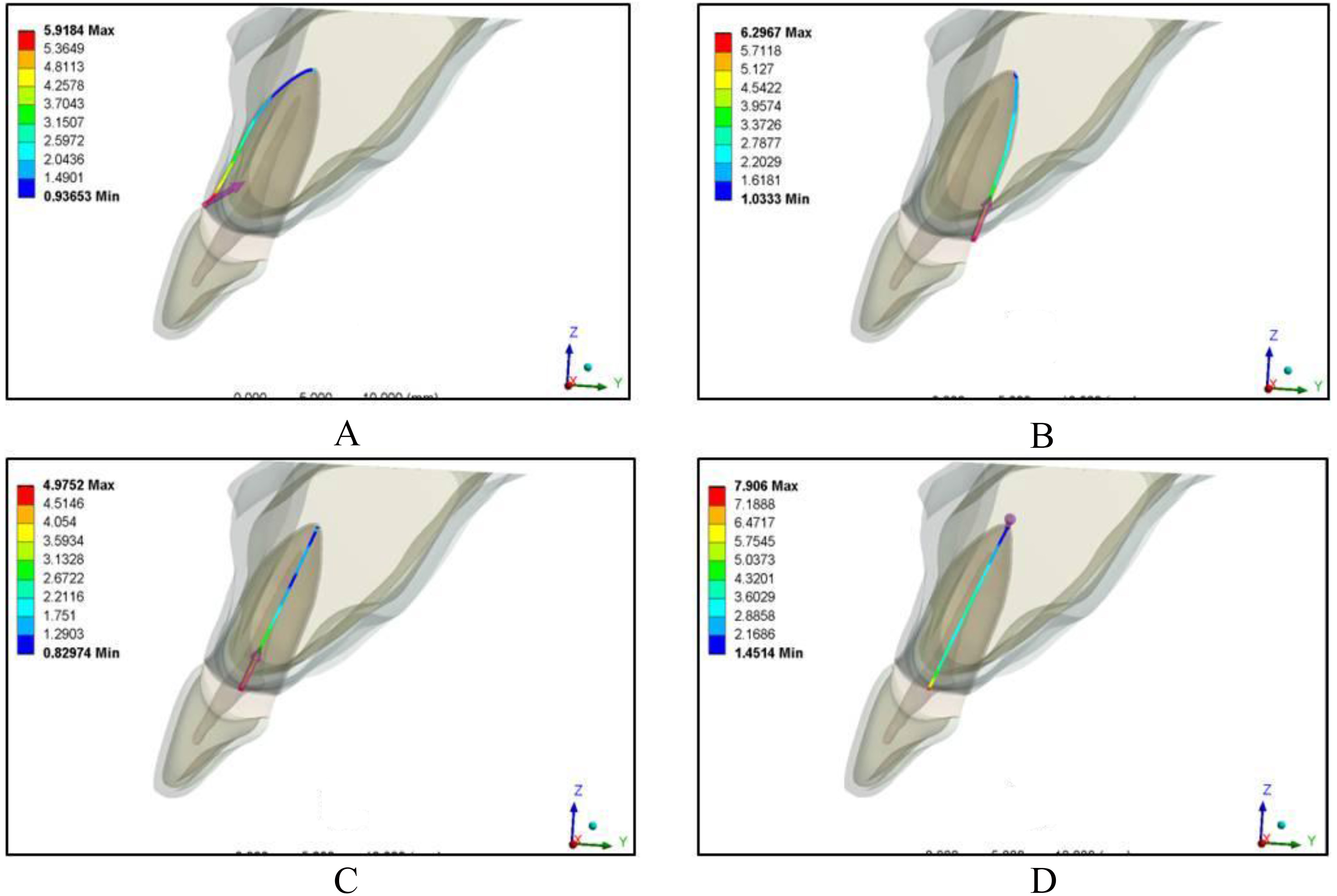
Figure 5.
The equivalent stress of labial line at each angle of different types of maxillary central incisor.
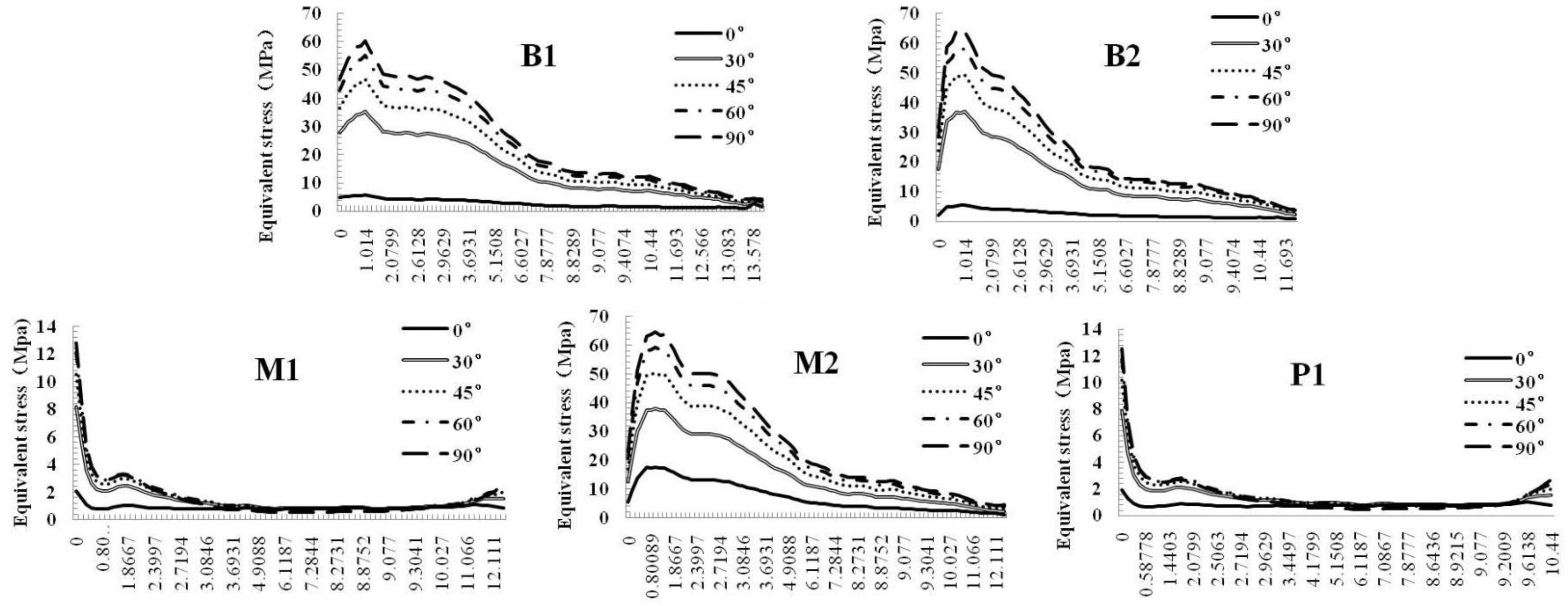
For the five types of maxillary central incisor (Fig. 4), the equivalent stresses at the four lines were increased with an increase in the angle of the loading force. The peaks of the equivalent stress at the four lines were shown at 0.8–17 mm below the cementoenamel junction (CEJ), and each equivalent stress generally decreased with an increase in the distance from the CEJ to apex of the root. The closer to the apex, the smaller the equivalent stress was. The M1 and P1 maxillary central incisors showed a sudden decrease of the equivalent stress on the buccal side at 1–10 mm below the CEJ, a sudden decrease of the equivalent stress on the lingual side at 17–19 mm, a sudden decrease of the equivalent stress on the mesial side at 10–18 mm, and a sudden decrease of the equivalent stress on the distal side at 12–14 mm. Furthermore, the fluctuation ranges of the equivalent stress at the four lines were small, with the peaks generally lower than those of the other three types. The fluctuation ranges of the equivalent stress at the four lines were especially large in the B2 maxillary central incisors, with high peaks. In addition, for the five types of maxillary central incisor, the equivalent stresses at the mesial tooth neck and the distal tooth neck were generally lower than those on the lingual and buccal sides, which followed the descending trend of buccal, lingual, distal, and mesial equivalent stress. The distribution of the maximum principal stress showed the same trend as the equivalent stress. (Fig. 5)
3.3Distribution of displacement at the four lines in different types of maxillary central incisor
The vertical ordinate of the line graph (Fig. 6) is the overall displacement of the teeth (unit: mm), the horizontal ordinateis the distance between the dental cervix to the root tip (unit:mm).
Figure 6.
Distribution of displacement at the four lines in B1 type of maxillary central incisor. A: lingual line; B: palatal line; C: mesial line; D: distal line.
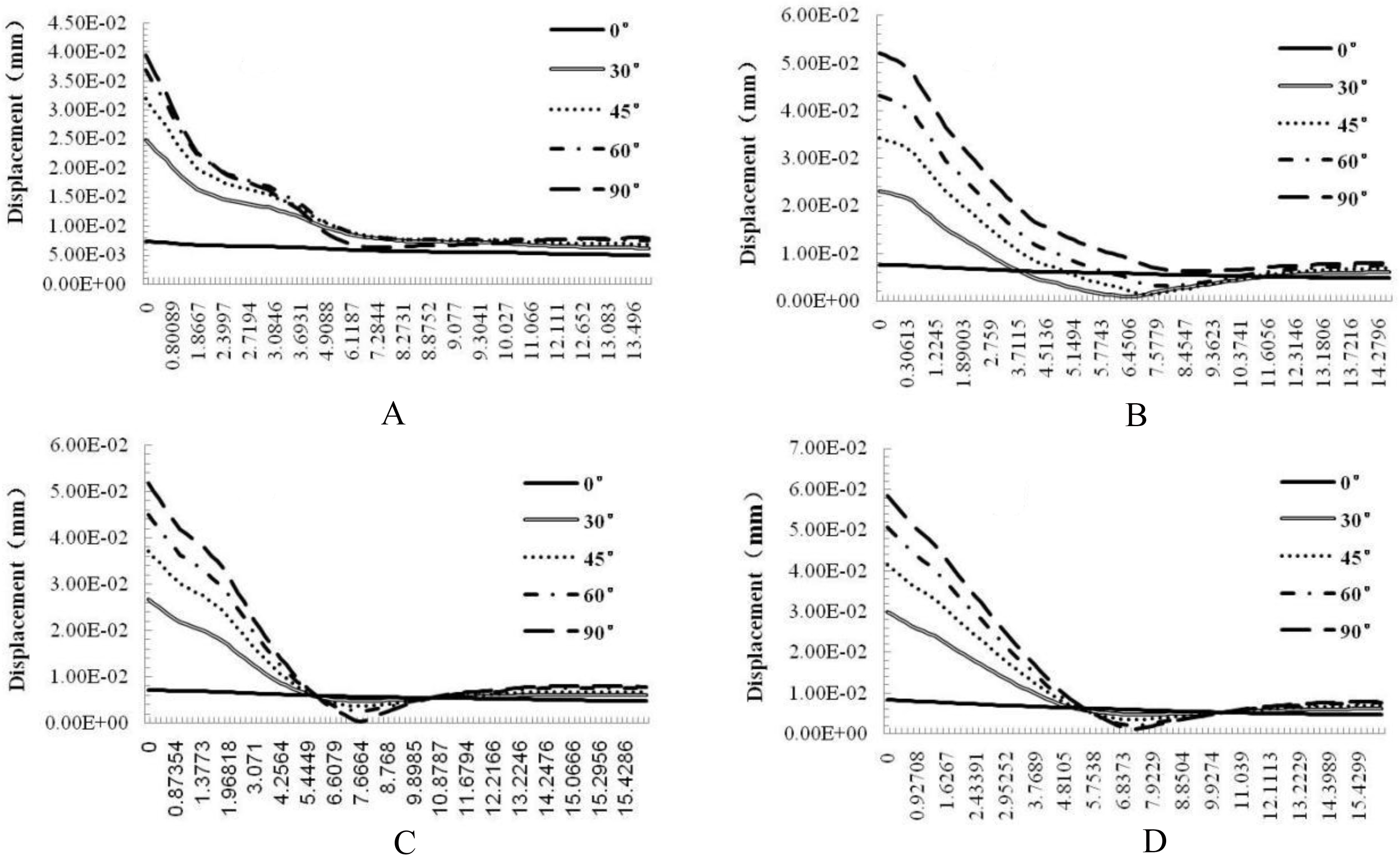
The displacements at the four lines were increased with an increase in the angle of the loading force, reaching the highest value in the neck of the tooth, showing a steep decline within 7 mm below the CEJ, and a gentle change from 7 cm to the apex. In general, the displacement value decreased while approaching the apical portion.
In addition, for the five anatomical types of maxillary central incisor, the displacement values at the palatal, mesial, and distal tooth neck were slightly higher than the labial displacement. (Fig. 6).
3.4Stress distribution in the periodontal ligament of the maxillary central incisor
The abscissa of line graph A was the angle of the loading force (unit:
Figure 7.
Stress distribution in the periodontal ligament of the maxillary central incisor.
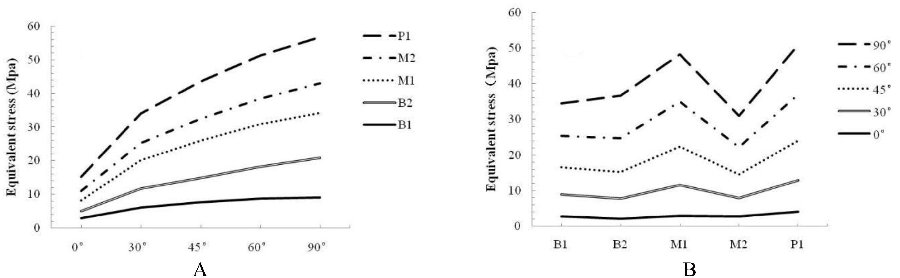
The abscissa of line graph B included the five different anatomical types, and the lines, respectively represented the different loading angles. The line graph showed that the equivalent stress on the periodontal ligament was the largest in the P1 and the lowest in the M2 incisors; the equivalent stress on the periodontal ligament at 0
4.Discussion
Three-dimensional finite element analysis is a method commonly used in biomechanical research. The most basic and most critical step of the three-dimensional finite element method is the accurate establishment of a finite element model, and the accuracy of the modeling will affect the accuracy of the results [6]. IAVP Poiate et al. [7] compared the accuracy of the simplified two-dimensional model and three-dimensional model of the maxillary central incisor and found that their trends of stress distribution were similar but the stress values were greatly different, and the results of the two-dimensional model could not represent the anatomical structure configuration of the complex teeth. Therefore, how to obtain the high-resolution image data became the primary task of modeling. In this study, DICOM direct data modeling (with a high modeling accuracy) was used [8].
This study simulated the clinical upper anterior bite force and angle, to, respectively load onto the different sites of the buccal, lingual, mesial, and distal sides of the central incisor at different angles to the long axis of the tooth, with a static load force of 100 N. It had high validity and wide coverage, showing strong representation [9, 10].
The maxillary central incisor is a typical indicator of facial aesthetics in anatomy, which is closely related to its anatomic structure and bite force. The mandibular database for the Chinese population shows that the maxillary central incisor differs inside the alveolar bone [4, 11]. Its major axis and the maxillary major axis are generally neither in the same direction nor parallel. Additionally, the distance between its root and the labial-palatal bone plate is also very different, causing complications in the reconstruction of resorbed alveolar and gingival recession after tooth extraction in the clinical practice of oral therapy, which directly affects the success of later implantation or appearance. Therefore, there are several anatomical types of maxillary central incisor, and it is necessary to understand their different characteristics in stress distribution. Kan et al. [12] proposed three classifications based on the position and implant direction of the natural maxillary central incisor, suggesting that the maxillary central incisors of different races have different, specific characteristics. In addition, Lau et al. reported that, in humans, there are several types of maxillary central incisor, which can be classified as nine types (B1, B2, B3, M1, M2, M3, P1, P2, and P3) based on the observation of the alveolar shape, the angle between the tooth root and alveolar process, the thickness of the labial bone plate, the length of the root in the tooth socket, and the distance between the apex and labial bone plate in the sagittal image. Further statistics showed that five types – B1, B2, M1, M2, M3, and P1 – are the most common [4]. In this study, the five common types of maxillary central incisor (B1, B2, M1, M2, and P1) reported by Lau et al., which are also the common types in Chinese people, were directly selected.
In this study, various equivalent stresses of five types of maxillary central incisor were all increased with an increase in the angle of the loading force, which is consistent with the results in the study of Fan Yubo et al. [13]. A maximum value was observed in the P1 maxillary incisors, while a minimum was found in the B1 maxillary central incisors, confirming that the force tolerance for the bite force in the P1 maxillary central incisors was weaker than that in other types, and the force tolerances of the B1 and B2 incisors were relatively good [11]. In addition, the analysis of the equivalent stresses at the four lines showed that the M1 and P1 maxillary central incisors showed a sudden decrease in the buccal, lingual, mesial, and distal equivalent stresses at 1–19 mm below the CEJ, while the change from the 2 mm below the CEJ to the apex was gradual, with a sharply declining trend in the higher position. The declining trend in the equivalent stresses at the four lines of other three types of maxillary central incisor, especially the B2 incisor, were similar, showing no obvious indication of a sudden decrease. This finding is also consistent with the survey result reported by Lau et al. that people with B2 maxillary central incisors account for up to 38.2% of the population, while people with M1 and P1 incisors only accounted for 7.7% and 1.8%, respectively [4]. The changing trends of displacement in the abovementioned, five types of maxillary central incisor in each of the four lines were similar.
For the five different angles of the loading force, the change at the angle of 0
The equivalent stresses at the periodontal ligament of all five types of maxillary central incisor were increased with an increase in the loading force angle, showing a rising trend. The equivalent stress at the periodontal ligament was the highest in the P1 incisors and the lowest in the M2 incisors. With an increasing depth of the root, the stress was rapidly reduced, which fully indicates that the periodontal ligament has a buffering effect.
5.Conclusion
The stress distribution on maxillary central incisors with a loading force at different angles changed significantly. The stress level on the dentin under a horizontal loading force (i.e., 0
In the B1, B2, and M2 incisors, the downward trends of the stress distribution were consistent and gradual, which explains the fact that the maxillary incisors in the majority of Chinese people belong to these three types. When the long axis of the central incisor and the long axis of the alveolar bone formed a certain angle, it had a certain protective effect, which was not common in the M1 and P1 incisors.
The high stress area of the natural periodontal ligament lies between the tooth neck and the middle of the root, while the stress level is very low from the middle of the root to the apex. The stress exhibited a large difference between the inner and outer surfaces of the periodontal ligament, indicating that the periodontal ligament has a significant buffering effect against stress.
Foundation items
The National Key Research and Development Program of China (2016YFC1102602); The Natural Science Foundation of China (31560265); The Science and Technology Plan of Shenzhen (JCYJ20140411150159436); The Scientific Research and Development Foundation of Shenzhen (CXZZ20130517140636687).
Conflict of interest
None to report.
References
[1] | Xu J, You J. Stress analysis of periodontal membrane and incisor and its clinical significance. Zhong Hua Kou Qiang Yi Xue Za Zhi, (1993) (1); 53-55. |
[2] | Okamoto K, Ino T, Iwase N, et al. Three-dimensional Finite Element Analysis of Stress Distribution in Composite Resin Cores with Fiber Posts of Varying Diameters. Dental Materials Journal, (2008) ; 27: (1): 49–55. |
[3] | Zaroneb F, Sorrentinob R, Apicellac D, et al. Evaluation of the biomechanical behavior of maxillary central incisors restored by means of endocrowns compared to a natural tooth: A 3D static linear nite? elements analysis. Dental Materials, (2006) ; 2: (2): 1035–1044. |
[4] | Lau SL, Chow J, Li W, et al. Classification of maxillary central incisors-implications for immediate implant in the esthetic zone [J]. J Oral Maxillofac Surg, (2011) ; 69: (1): 142–153. |
[5] | Lin YS, Lin CL, Chang WJ. Biomechanical evaluation of an orthodontic mini-implant with plastic removal cap: An in-vitro experimental testing. Conf Proc IEEE Eng Med Biol Soc, (2013) ; 3183–3185. |
[6] | Zhao F, Gao B, Liu Z. Establishment of a three-dimensional finite element model of mandible with Dicom and Mimics software. Southwest National Defense Medical, (2005) ; 15: (5): 479–481. |
[7] | Poiate IAVP, Vasconcellos AB, Matsuyoshi M, Edgard P. 2D and 3D finite element analysis of central incisor generated by computerized tomography. Computer Methods & Programs in Biomedicine, (2011) ; 104: (2): 292–299. |
[8] | Evans CD, Chen ST. Esthetic outcomes of immediate implant placements [J]. Clin Oral Implants Res, (2008) ; 19: (1): 73–80. |
[9] | Sun L, Lin ZY, Hu WD, et al. The Establishment of the 3D Finite Element Model of the Anterior Maxilla. Journal of Modeling and Optimization, (2014) ; 6: (2): 41–48. |
[10] | Hu XY, Dong FS, Lu HY, Ma WS, Yuan S. Establishment of the craniofacial three-dimensional finite element models with the sutures defined alone. Chinese Journal of Stomatology, (2013) ; 48: (10): 600–5. |
[11] | Romeo E, Lops D, Rossi A, et al. Surgical and prostheticmanagement of interproximal region with single-implant restorations: 1-year prospective study [J]. J Periodontol, (2008) ; 79: (6): 1048–1055. |
[12] | Kan JY, Roe P, Rungcharassaeng K, et al. Classification ofsagittal root position in relation to the anterior maxillaryosseous housing for immediate implant placement: a conebeam computed tomography study [J]. Int J Oral Maxillofac Implants, (2011) ; 26: (4): 873–876. |
[13] | Fan Y, Zhang X, Chen J. Three-dimensional Finite Element study on stress distribution in dentine of maxillary incisor under the loads with different angles. Journal of Sichuan Union University, (1998) ; 2: (6): 57–60. |

