
Study on the control of variable resistance for isokinetic muscle training system
Abstract
BACKGROUND:
Isokinetic muscle strength training is presently the most advanced method of muscle strength training. However, the existing control schemes of the training equipment are usually limited to the structure of the brake.
OBJECTIVE:
In order to solve this problem, this paper presents a solution to an isokinetic system based on the force control of a DC servomotor.
METHODS:
A new fuzzy impedance nonlinear controller is designed by analyzing the relevant requirements of isokinetic motion. A series of force tracking comparison experiments between a fuzzy PI controller and a classical PI controller are studied. In addition, some strength training experiments employing different driving forces and target speeds are also conducted.
RESULTS:
The results demonstrate the effectiveness of this fuzzy impedance force tracking control strategy.
CONCLUSION:
Using the aforementioned methods, a comprehensive motion algorithm was designed.
1.Introduction
With the developments of modern rehabilitation medicine, the techniques of isokinetic muscle strength measurement and training in muscle strength recovery are garnering considerable attention. Isokinetic muscle strength training is characterized by constant speed and adjustable resistance, which results in the best effect of strength training at any position of the joint [1]. With the help of the definition of isokinetic exercise, it is apparent that, no matter how much tension muscle generates, the movements of affected limbs are always carried out at a predetermined speed [2]. Isokinetic muscle testing and training are widely used in sports medicine, orthopedics, and rehabilitation medicine. Furthermore, isokinetic exercise training was able to significantly improve chronic stroke survivors’ strength and gait speed without concomitant increases in tone.
Recently, some researchers have studied an isokinetic instrument based on the principle of brakes. Dong et al. [3] proposed portable rehabilitation equipment based on a magnetorheological damper, which changes the magnetic field by means of an adaptive controller and subsequently changes the state of the magnetorheological fluid, thereby resulting in a match resistance. This new form of damper provided a new method for developing isokinetic training devices. Kikuchi et al. [4] developed an upper limb isokinetic rehabilitation device based on an electrorheological damper, and the related training effects were studied through experiments. Nikitczuk et al. [5] developed a knee rehabilitation device called AKROD, and some comparison experiments between AKROD and Biodex in isokinetic and isotonic contraction were conducted. Wang et al. [6] developed an isokinetic training device based on the principle of a throttle brake, which could change the resistance of the liquid flow by changing the orifice size of the liquid flow. Additionally, a controllable resistance, as required by isokinetic devices, can be obtained.
The aforementioned studies are all based on the principle of brakes. However, for some rehabilitation equipment, this approach will result in increased structural complexity. Therefore, this paper proposes a new muscle rehabilitation method based on the force tracking control of a DC servomotor, which benefits the expansion of isokinetic training from special isokinetic muscle training devices to external skeleton rehabilitation robots. Moreover, this method can simultaneously reduce the cost of an isokinetic apparatus, which will help promote a wide use of isokinetic training.
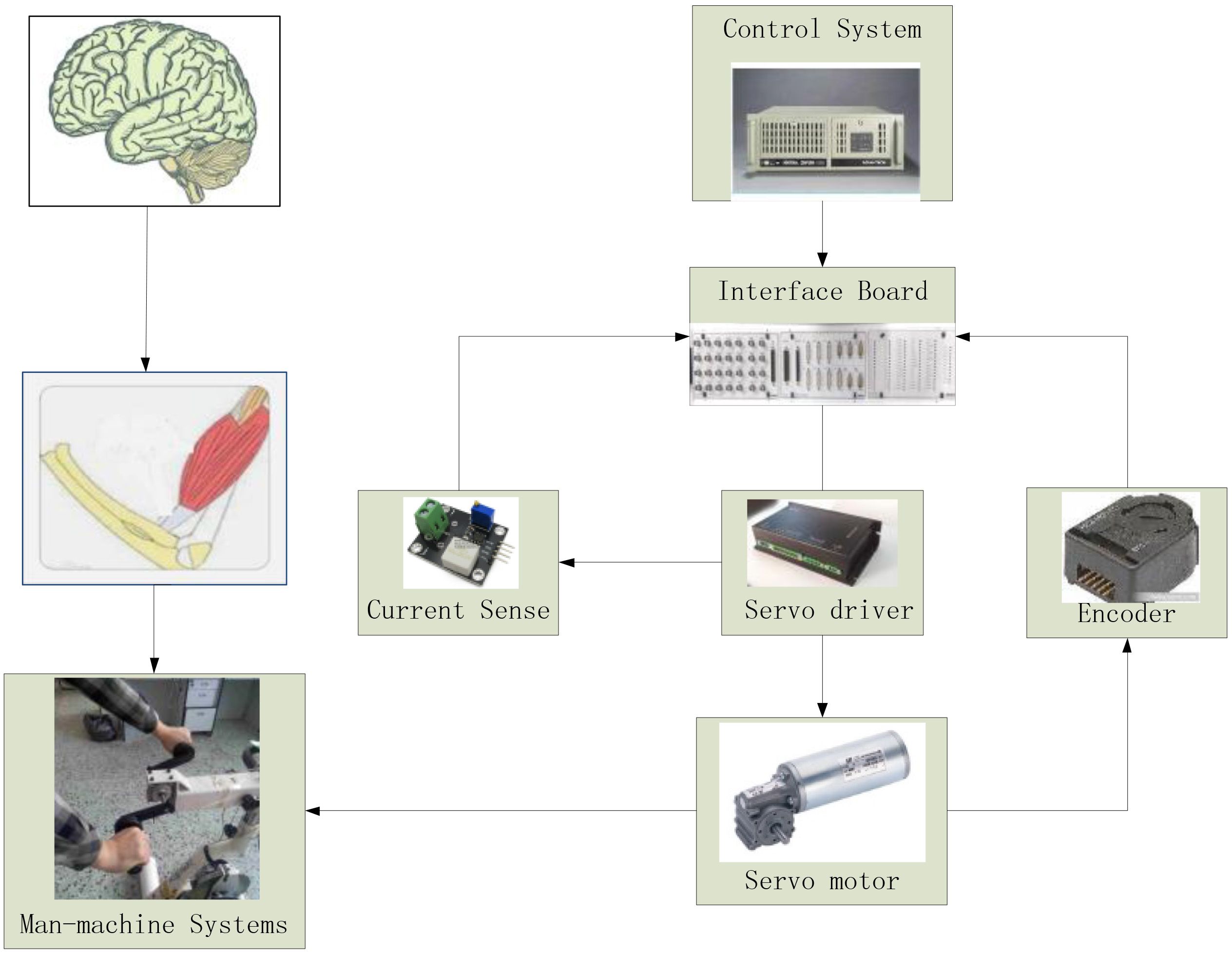
Figure 1.
The overall scheme of isokinetic training system.
2.Design of rehabilitation system
The overall scheme of the isokinetic training system is shown in Fig. 1. When the user exerts a driving force on the connecting rod of the rehabilitation device, the connecting rod rotates. The speed and armature current of the servomotor are collected by using an encoder and a current sensor, respectively. Once the speed of motion reaches the target speed, the system will generate resistance to automatically maintain a constant speed. Although the user changes the joint driving torque, the control system can also rebalance the active torque and the matching torque.
There are several methods for obtaining the matching torque [7, 8, 9]; however, these methods require additional sensors to measure the relevant data. For this point, a simple and effective method is given in this paper, such that it can take a small deviation of velocity as the basis for predicting the matching torque. As for the given matching torque of tracking control, it is often indirectly implemented with a current closed loop in practice. Therefore, an integral part must be used in the force control loop [10].
3.Design of fuzzy control
The isokinetic training system is a man-machine coupling system. In the analysis, the effect of the human body on the system is simplified as the external torque.
The training system can be regarded as a mass spring damper system. The torque balance equation of the model is given below:
(1)
where
The system contains the torque generated by the motor and the external torque on the motor shaft. In addition, the effect of the heavy moment of inertia on the system is also considered. Thus, the equation can be given as follows:
(2)
where,
Because the system needs to provide a compliant resistance, an impedance force tracking control algorithm is used [11]. The basic equation is given below:
(3)
where
During isokinetic exercise, the expected acceleration is equal to zero. Because the actual acceleration is also very small, the inertia moment is ignored. Moreover, the expected position is not planned in isokinetic exercise. Furthermore, isokinetic exercise requires that the resistance be equal to zero when the speed is less than the target speed. Therefore, a nonlinear link is introduced in the impedance controller. In order to achieve optimal control, a fuzzy damping controller is designed. The impedance control equation can be modified as follows:
(4)
According to the human skeletal muscle model, the joint torque is related to muscle force and the moment arms of joint motor tendons [12, 13, 14], which makes matching the torque more complicated. Thus, a fuzzy PI controller is adopted to more accurately track the trajectory of the joint moment. By controlling the armature current, the output torque of the motor is indirectly controlled. The following is the output torque equation of the controller:
(5)
where,
Figure 2.
The block diagram of fuzzy impedance control scheme.
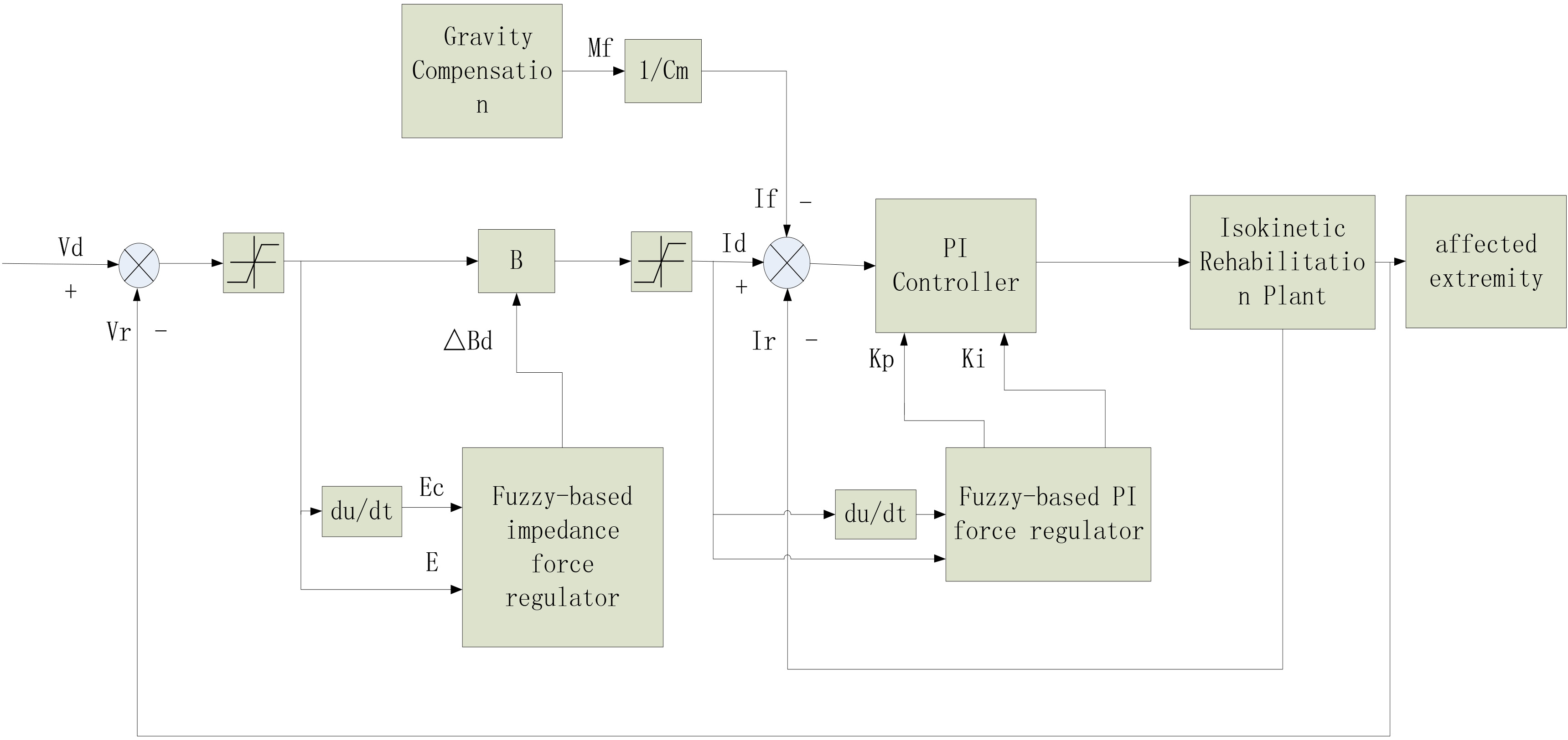
The structure of the fuzzy impedance controller is shown in Fig. 2. The controller includes a fuzzy impedance part, a fuzzy PI part, and a compensation link. In this paper, the experimental platform is affected by a small weight torque, so the compensation moment will be set as zero.
According to the performance requirements of the system, the domain of velocity error, the change rate of velocity error, and the increment of damping parameter are set as [
4.Experiments and results
This experimental platform consists of a rehabilitation device, a drive circuit, and a dSPACE HIL simulation platform, as shown in Fig. 3. The experiments are formed by a force tracking experiment and an isokinetic muscle strength training experiment, which test the performance of the inner loop and outer loop, respectively.
4.1Force tracking experiment
The force tracking experiment is primarily used to test the response of the controller under different step signals. The classic PI controller is selected as the comparison group. The proportional gain and the integral gain of the classic PI controller are 540 and 13.3, respectively. The domain of
Table 1
Statistical results of current tracking experiments with different control algorithms
| Subject | Controller type | 0.2 A | 1 A | 2 A | 3 A | 4 A | 5 A |
|---|---|---|---|---|---|---|---|
| Maximum overshoot (%) | PI | 0 | 1 | 0 | 0 | 13 | 20 |
| FPI | 0 | 4 | 3 | 1.5 | 3 | 2 | |
| Rise time (ms) | PI | 450 | 200 | 70 | 150 | 50 | 70 |
| FPI | 130 | 50 | 60 | 60 | 50 | 80 |
Figure 3.
Isokinetic training platform.
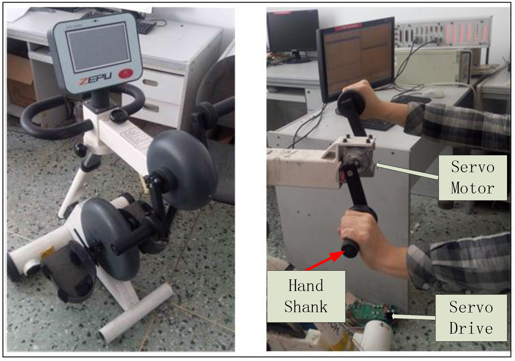
Figure 4.
Results of the current tracking experiments. Amplitude is set at (a) 0.2 A, (b) 1.0 A, (c) 2.0 A, (d) 3.0 A, (e) 4.0 A, and (f) 5.0 A.
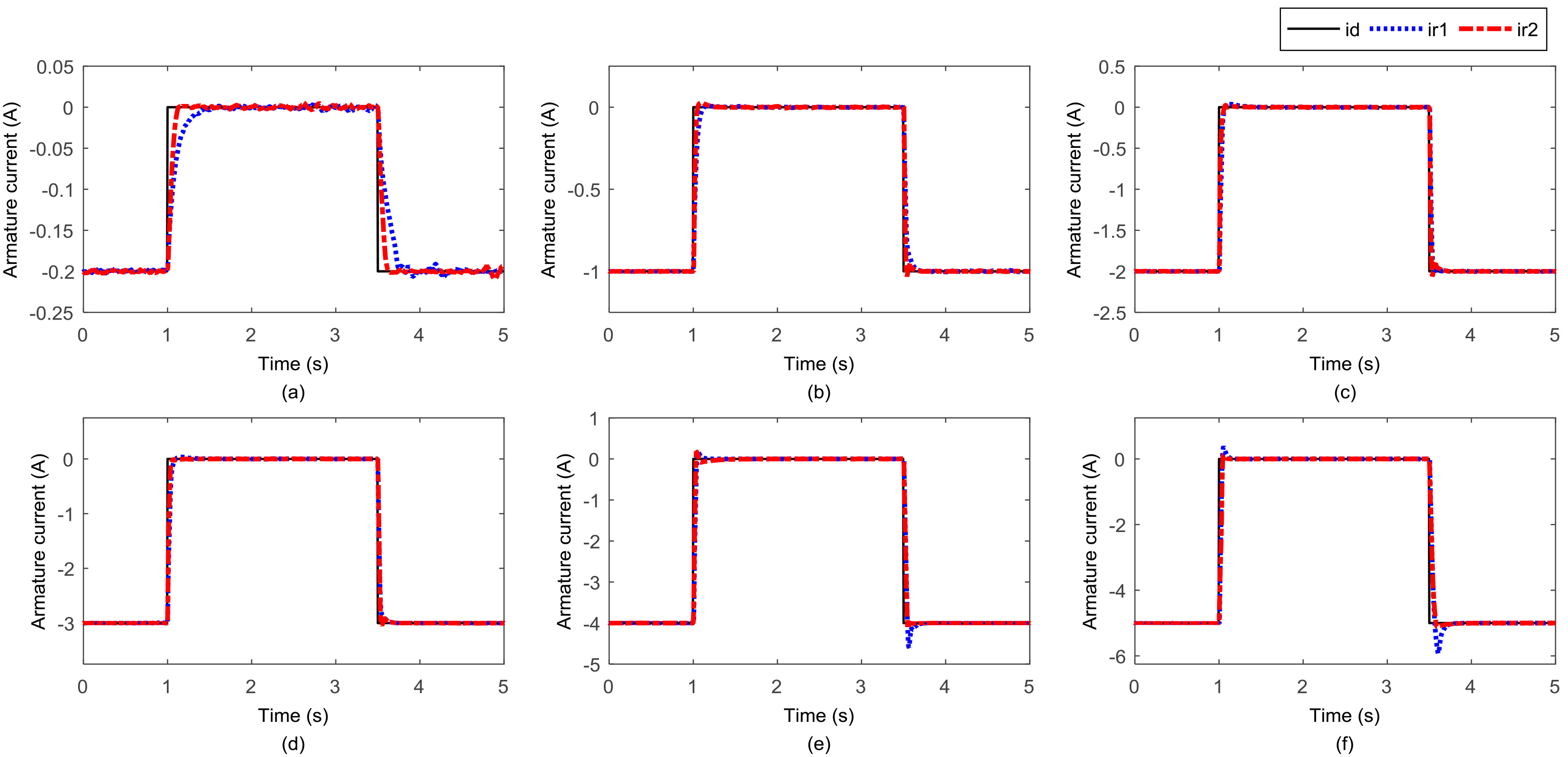
In Table 1, it can be seen that neither the response of the FPI controller or the PI controller overshoot when the step signal is 0.2 A, and the rise time of the PI controller is 450 ms, which is much longer than the rise time of the FPI controller. When the given current is set to 1 A, 2 A, and 3 A, the maximum overshoot of the PI controller is less than 1%, but the rise time of the FPI controller is better. When the given current is set to 4 A and 5 A, the maximum overshoot of the PI controller reaches 13% and 20%, respectively, beyond the reasonable range of the system. As mentioned above, there is evidence that the FPI controller is better than the PI controller.
4.2Isokinetic training experiment
The isokinetic training experiment is used to verify the effectiveness of the control algorithm. Taking into consideration the reliability and the feasible operability of the experiment, three muscular, healthy males are chosen as the experimental subjects. Their ages are 24, 25, and 26 years old. The experiment consists of two parts. During the first part of the experiment, the subject shakes the handle using the different force, and the target speed is set as 20 r/min. The response is shown in Fig. 5.
Figure 5.
Results of the first part of the isokinetic training experiment. (a) The speed of a lesser torque. (b) The current of a moderate torque. (c) The speed of a larger torque. (d) The current of a lesser torque. (e) The speed of a moderate torque. (f) The current of a larger torque.
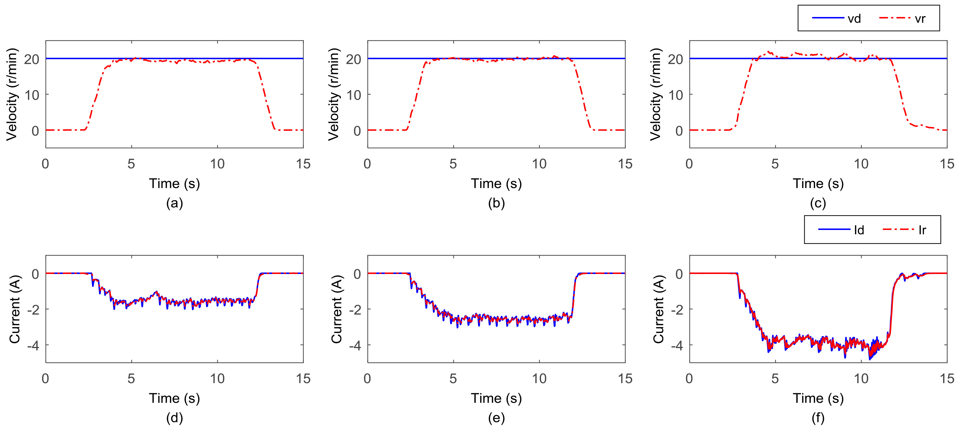
Figures 5(a) and (d) show that when the given current remains around 1.5 A, the speed error fluctuates between
In the second part of this experiment, the target speed is set as 20 r/min, 30 r/min, and 40 r/min, and the driving force is changed from small to large. The control effect is shown in Fig. 6.
Figure 6.
Results of the second part of isokinetic training experiment. (a) The speed that target speed is set to 20 r/min. (b) The speed that target speed is set to 30 r/min. (c) The speed that target speed is set to 40 r/min. (d) The current that target speed is set to 20 r/min. (e) The current that target speed is set to 30 r/min. (f) The current that target speed is set to 40 r/min.
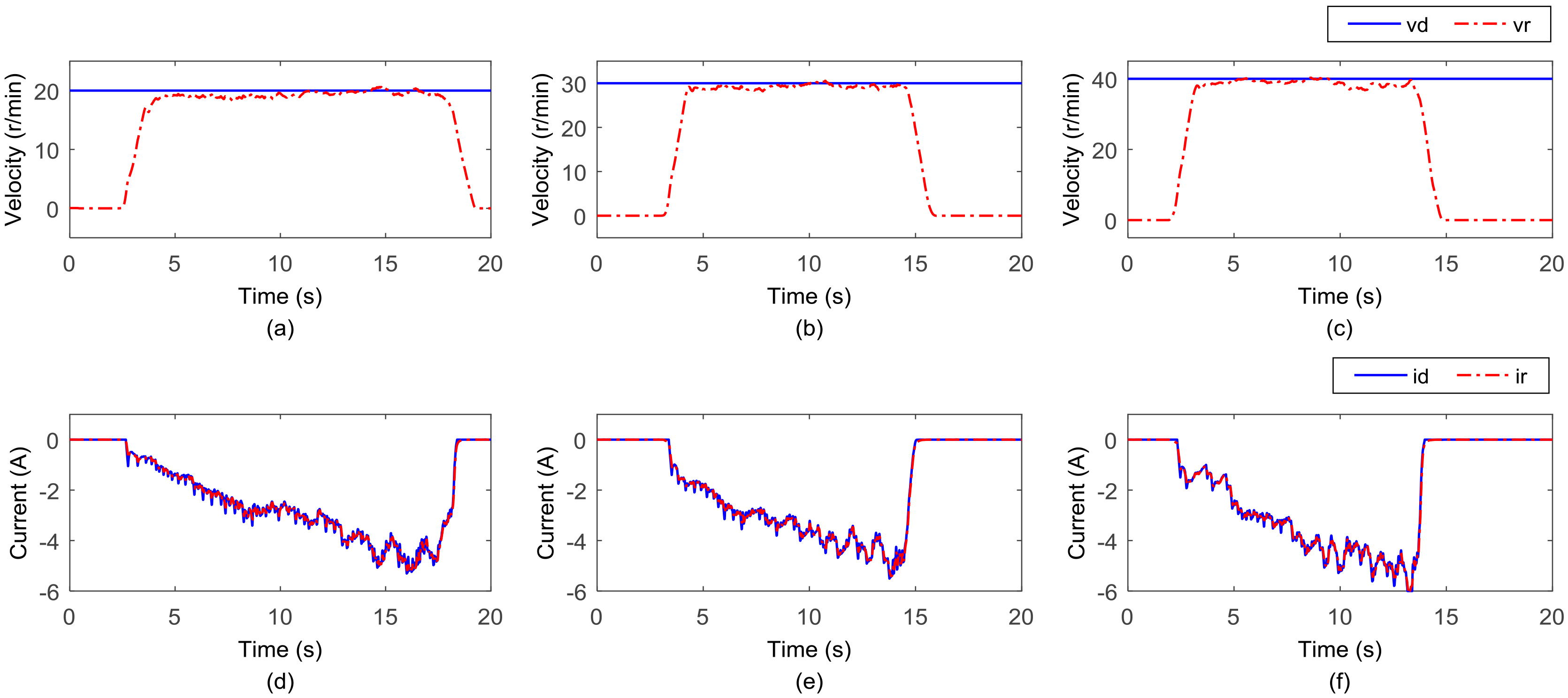
As shown in Figs 6(a) and (d), when the target speed is set at 20 r/min and the given current gradually increases, the speed deviation remains in the
5.Conclusions and future works
The traditional control strategy of an isokinetic muscle strength training instrument is limited to the structure of the brake. This paper, however, presents a new solution for solving this problem for isokinetic systems, and this new method is based on the force control of a DC servomotor. A fuzzy impedance force tracking controller is proposed in this new scheme, and the real-time adjustment of system resistance ensures that the system speed is essentially equal to the given speed. Then, a series of force tracking experiments and isokinetic muscle strength training experiments were conducted, and the results demonstrate the effectiveness of the control strategy.
Future work will focus on the inspection and improvement of the control effect because there is a ripple in the system when the external force is larger, and the change rate of the velocity deviation increases.
Conflict of interest
None to report.
Acknowledgments
This research is supported by grants from the National Natural Science Foundation of China (grants 51405095) and Harbin Foundation (grants 2014RFXXJ101).
References
[1] | Song YL. Isokinetic muscle rehabilitation and the approach to realizing isokinetic motion, Journal of Shanghai Dianji University, (2006) (5), 5-9. |
[2] | Huang ZP, Yin Y, Liu M. Research evolution of the isokinetic technology in testing and training, Sport science: Guang xi, (2011) (4), 52-58. |
[3] | Dong S, Liu KQ, Sun JQ. Rehabilitation device with variable resistance and intelligent control, Medical Engineering and Physics, (2005) , 27: (3), 249-255. |
[4] | Kikuchi T, Furusho J, Oda K. Development of isokinetic exercise machine using ER brake, Proceedings of IEEE International Conference on Robotics and Automation, Taipei, Taiwan, (2003) ,214-219. |
[5] | Nikitczuk J, Weinberg B, Canavan PK. Active knee rehabilitation orthotic device with variable damping characteristics implemented via an electrorheological fluid, Mechatronics IEEE/ASME Transactions on, (2010) , 15: (6), 952-960. |
[6] | Wang Y, Shen B, Song Y. Development of Key Device for Isokinetic Human Muscle Rehabilitation System, Journal of Shanghai Dianji University, (2011) . |
[7] | Li HJ, Liu H, Zhang X. Development of estimation of the muscle force distribution of joint, Journal of Beijing Sport University, (2013) . |
[8] | Pang M, Wang J, Fu J et al. Interaction force prediction between human and environments based on surface EMG, Journal of Huazhong University of Science and Technology, (2015) . |
[9] | Ryait HS, Arora AS, Agarwal R. SEMG signal analysis at acupressure points for elbow movement, Journal of Electromyography and Kinesiology Official Journal of the International Society of Electrophysiological Kinesiology, (2011) , 21: (5): 868-876. |
[10] | Liu YW, vWang GX, Li J, Qi ZG. Design problems of force control systems, Electric Machines and Control, (2011) , 15: (4), 98-102. |
[11] | Xu GZ, Song AG, Li HJ. Experimental study on fuzzy-logic-based impedence control for upper-limb rehabilitation robot, Robot, (2010) , 32: (6), 792-798. |
[12] | Hackett L, Reed D, Halaki M. Assessing the validity of surface electromyography for recording muscle activation patterns from serratus anterior, Journal of Electromyography and Kinesiology Official Journal of the International Society of Electrophysiological Kinesiology, (2014) , 24: (2), 221-227. |
[13] | Bai J. An elblow biomechanical model on semg, M. A. Dissertation, Harbin Institute of Technology, (2014) . |
[14] | Zhang ZH. Study of bone-muscle modeling and muscle force prediction method of human upper limb, M. A. Dissertation, Tianjin University, (2012) . |


