
Interactive evacuation in intelligent buildings assisted by mixed reality
Abstract
Intelligent buildings offer a great opportunity to evacuate people more efficiently and safely by using dynamic evacuation guidance systems in comparison to static escape route signs. Static systems are unable to react to temporary events; their signs might guide the occupants directly to the hazard in the worst case. A dynamic system on the other hand determines the hazard position and calculates and displays an alternative escape route to avoiding the hazard position. In this work, we present a detailed study of current research approaches and introduce two algorithms developed for building evacuation. The first algorithm demonstrates the static evacuation and leads directly to the nearest exit. The second algorithm reacts dynamically to temporary events such as fire. A comparison of these algorithms shows that the dynamic system is more efficient. In order to test the dynamic approach in a real environment, a device to display the evacuation route is required. We propose a novel interactive evacuation approach using mixed reality glasses (HoloLens) for user guidance. A user study shows the advantages of the HoloLens and verifies our findings from the simulation in a real environment.
1.Introduction
Smart cities are designed to proactively improve human lifestyles, including healthcare, social inclusion, human support, quality of life, lifelong learning, adapted transport, and smart buildings. Developing intelligent environments that help society, make their lives better and safer, and at the same time are accepted by society is a complex challenge. Similarly, IE has to be high-performance and responsive to increase user acceptance. Moreover, an intelligent environment should not influence or restrict the users too much in their natural behavior. Only if the intelligent environment complies with these requirements, it does have a realistic chance of being accepted by users. Especially for our work, the interactive escape routing in the intelligent building, it is important to develop an environment that is very robust and gives the users a high degree of security, so that the users trust the system in case of an emergency and follow the signage.
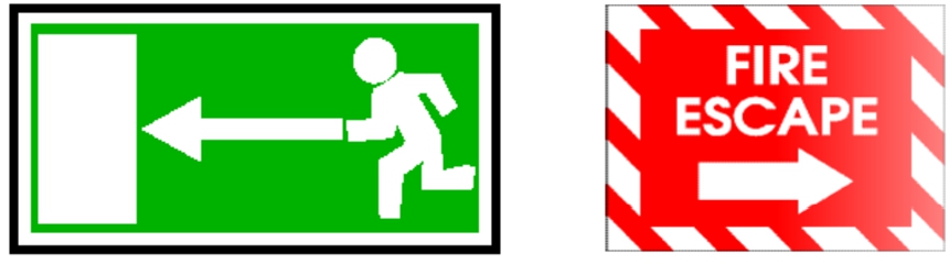
The focus of this paper is on fire protection and the evacuation of new and existing buildings. At present, static escape route systems are used in a wide range of existing and new buildings. Figure 1 shows two escape route signs. The left image indicates a static escape route to the left and the red sign indicates a static escape route to the right. The disadvantage of these systems is that the escape routes are not alterable and, thus, not able to react to temporary events (fire, blocked paths, toxic gases, etc.). The position of the signage is also determined during the building design and then placed inside the building. The positions of the signage are usually very high up, so they are difficult to see through dense smoke. Another disadvantage of static signage is that the signs indicate the shortest way from the position where they are placed. In the worst-case scenario, the signs lead occupants directly to the hazard [25].
In order to analyze the potential of interactive evacuation systems, we have developed two algorithms for building evacuation and simulated them in the Unity3D game engine. The first algorithm simulates the behavior of a static evacuation and measures various parameters such as time traveled, distance traveled, people led to the hazard, and people who had to find a new way out. The second algorithm simulates dynamic evacuation from buildings. The algorithm is able to react to temporary events such as fire, blocked corridor or fully exhausted capacity of corridors or obstacles. Like the static algorithm, the dynamic algorithm calculates first the shortest way out of the building. If this route is blocked by one of the causes mentioned above, the second closest route is calculated without passing through a hazard and so on. The algorithms are further described in Section 3.6. In our study comparing the two algorithms, we found that dynamic escape routes have great potential to evacuate buildings more safely and efficiently.
To achieve a realistic assessment, we transferred our dynamic algorithm to evaluate it in the real world. Furthermore, we aimed the use upcoming mixed reality technology for our purpose. To this end, we used a HoloLens from Microsoft. The display in the glasses show the user an arrow in the direction he has to walk to reach the next exit. The arrow leads to the nearest exit which is calculated by the dynamic algorithm. Moreover, the glasses display the building plan. In its visualization, the escape route is highlighted as a green escape route in the building plan. Further, the user’s position is displayed on the map and is constantly updated. We use Beacons to determine the position of the user in the building. By using the HoloLens, building evacuation can be assisted, trained, and analyzed.
Fig. 1.
Typical static evacuation signs.
2.Related work
Buildings are getting bigger and more complex, increasing the capacity of people in the building and decreasing the space for each individual, thus more and more people are in a confined space. Therefore, it is even more important to evacuate buildings in an emergency situation as effectively and safely as possible. Various approaches are used to simulate such evacuation scenarios. At the beginning of the development of a simulation, the level of detail of the environment and the evacuees needs to be determined.
A distinction is commonly made between macroscopic and microscopic scale [4,19]. Macroscopic models are one-dimensional structures, which means that people have the same walking direction on the macroscopic scale (e.g., corridors in a building, pedestrian walkways). However, this scenario can also be observed in open spaces, e.g., when crowds of people move towards an entrance. Microscopic models are characterized by the fact that each individual person within a building is modeled, depending on the model, the corresponding person has individual parameters that distinguish him from other persons (e.g., walking speed, height, width).
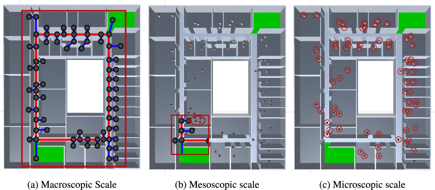
Additionally, there are mesoscopic models (Fig. 2(b)) which are located between microscopic and macroscopic models in terms of the level of detail. This model is used when there is a trade-off between the computational power and the level of detail [3]. The advantage of macroscopic models is performance as models adopt simplified assumptions. Macroscopic models are usable even on less powerful hardware. Microscopic models provide the opportunity to study individuals with different characteristics. The advantage is the ability to adapt the model very well to the scenario, thus making it very flexible to utilize. Furthermore, due to the high level of customizability, detailed findings can be made. Figure 2(a) shows the result of the calculation of the escape routes in the macroscopic model. This model is based on the graph and the visualized environment does not influence the calculation. The graph contains nodes and edges. A node describes the connection of edges and is shown as a sphere in Fig. 2(a). An edge can be uni- and bidirectional and describes a corridor (e.g., the length of the corridor, capacity, or structural conditions), cf. [4,25]. The red edges in this figure represent bidirectional edges (walkable in both directions) and the blue ones represent unidirectional edges (dead-end, walkable only in one direction). Figure 2(c) shows a microscopic model that represents each occupant in the building by an agent. Each agent can thus have different properties (e.g., body size, body radius, walking speed, visibility…) and has his own behavior.
Fig. 2.
Illustration of the differences between macroscopic, mesoscopic, and microscopic scales. The red markers show the relevant information for the respective scaling levels.
Various methods have been proposed to implement the above-mentioned models. An agent-based simulation tool, in the Python programming language, was developed to evacuate university buildings [9]. Fire Dynamics Simulator (FDS) in combination with EVAC are used to simulate fire scenarios and calculate escape routes [2]. By combining FDS + EVAC, agent-based simulation of people and simultaneous fire outbreaks can be simulated. The Consolidated Model of Fire Growth and Smoke Transport (CFAST) is a model that simulates the temporal distribution of smoke, smoke, and temperature in a building [15]. CrowdSim is used for simulation of people’s behavior and its motion [5]. Temporary events like obstacles or doors can be bypassed or as opened by agents. Agents can panic and push their way through a crowd or panic other people as well.
The cross-platform game engine Unity 3D provides a comprehensive set of features for simulating building evacuation. Unity is a suitable tool to train evacuation scenarios and to understand the group behavior of occupants during an evacuation [17]. In addition, Unity can be used to investigate the influence of spreading hazards (e.g. fire spreading) in the building [26]. Furthermore, Unity was used to simulate the evacuation of hospital occupants in need of assistance [16]. The system classifies the occupants into three types. The first group has no impairments in their mobility in any way and they can follow the escape route to the exit (outside the building) on their own. The other two types have limitations and are unable to leave the hospital by themselves, therefore they require help from the hospital staff to leave the building. Agent type two (“dependent”) requires a wheelchair and has to be pushed out of the building by a nurse. The last type of patient is bedridden and has to be evacuated from the building in bed with the assistance of the hospital staff. By using different assistance in evacuation, a modified wayfinding was implemented for each type.
A scientific investigation of Unity to determine if the engine is suitable for the simulation of microscopic models is made [4]. For this purpose, they examined 15 criteria (movement of an agent, maintenance of speed in a corridor, effects of bottlenecks, etc.) to verify if Unity complies with the RiMEA11 standard. In total, Unity completely fulfills ten requirements, four requirements are partially fulfilled and 1 one requirement could not be fulfilled by Unity. The result of the study indicates that Unity is suitable for microscopic escape analysis and serves as a powerful tool for decision support of safety-related considerations. Real conditions can be taken into account by embedding BIM models. All of the above work shows that Unity is capable of generating and analyzing quantitative and qualitative results in the field, of fire simulation, evacuation scenario evaluation, and building design [4,16,17,24,26]. The field of indoor localization is a large area of research that is constantly evolving. Therefore, we focused on the work of [1,7,13].
Depari et al. [7] developed a native Android mobile application for building evacuation. The app calculates the shortest way to the nearest exit and shows the user an arrow indicating the direction to the exit. Furthermore, the app displays the distance to the exit. Additionally, a rescue app was developed that shows the shortest way to the node where the alarm was triggered. A web application offers the possibility to enter necessary data into the system and display the information of the web server. The web server is the control center of the system and receives the alarm and transmits it to the apps.
Beacons were used for indoor localization. The distance to the beacons is determined based on the Received Signal Strength Indicator (RSSI). The position of the user is set the same as the position of the beacon with the strongest signal. No triangulation was used.
Lin et al. [13] developed a mobile application that helps medical staff save time by finding their patients. The server component is used to save, read and map data and serves as the interface between the patient app and the monitoring site, as well as assigning the estimated nearest beacons sent by the patient app to the locations of the corresponding subareas. The monitoring site component displays patient location information to medical staff via a web browser or mobile device. The indoor localization is done via Bluetooth Low Energy Beacons based on the iBeacon standard. They used RSSI based localization method to estimate the patient’s location. They found that the signal strength is strongly affected by obstacles and walls whereby the accuracy of the position varied between 3 and 5 meters, giving a mean accuracy of 97.22%.
Ahn and Han [1] developed an indoor augmented-reality evacuation system for smartphones. The mobile android application shows the user the escape route and the distance to the exit in an augmented way. Furthermore, the app takes snapshots of the nearby room numbers, which are used for image-based positioning. In addition, a personalized pedometer algorithm was developed that estimates user steps to increase positioning accuracy for mobile phone users of this system. An external image labeling Service (IQ Engines) is used to identify the room numbers from the snapshots of the mobile application. The RescueMe server calculates the evacuation route focusing on the evacuation time. This implies that it is possible that the user will not be led the shortest route, as it could be overcrowded and the system detects this and shows the user an alternative evacuation path.
Table 1
Summary of the mentioned preliminary works in terms of dynamic evacuation systems
| References | Building representation | Algorithm (basis) | Architecture | Parameters |
| [23] | Graph | Dijkstra | Central | Roomsize, fire position |
| [27] | Graph | Dijkstra | Central | architectural space, passageway |
| [10] | Graph | Dijkstra | Central | Floor capacity, time to pass the corridor |
| [25] | Graph | Dijkstra | Central | Structural building conditions, fire position |
| [22] | Graph | Dijkstra | Decentralized | Corridor length, fire position, user position |
| [24] | Graph | Dijkstra | Central | Fire position, floor capacity, floor length, room capacity |
| [6] | Graph | Link reversal | Distributed | Corridor capacity, corridor length, exit capacity, concurrent move, people distribution |
| [28] | Graph | Biased min-consensus approach | Distributed | Distance |
| [11] | Graph | A* | Central | Walking speed, knowledge of the environment, environment, degree of courage |
An overview of the relevant approaches to dynamic evacuation systems, with the criteria building representation, algorithm, architecture, and parameters is shown in Table 1. Remarkably, all mentioned works use a mathematical graph for the building representation, and except for [6] and [28] they all use the Dijkstra or A* algorithm. In addition, all approaches that use the Dijkstra or A* algorithm rely on centralized system architecture. The approaches differ most in the characterization of the graph, which reflects the focus of the system. Tabirca et al. [23] uses the capacity of the room to calculate the escape route and consider the position of the fire. The algorithm aims to evacuate the occupants in the fastest possible time, assuming that there is only one exit. A further proposed system developed an algorithm that is optimized to minimize the speed of evacuation based on the structural conditions and passageway [27]. Guo et al. [10] parameterizes the weighted graph with the corridor capacity and the time needed to pass the section. Alternatively, a questionnaire was developed for the weights of the edges in the graph, which maps the expert knowledge about structural conditions in the fire protection context [25]. The catalog is used to describe and quantify floor sections in detail. The proposed evacuation system aimed to evacuate a building smoothly and reliably [22]. Therefore Beacons were used to locate people in the building. Each beacon represents a node in the graph. The graph serves as the basis for calculating the escape routes. The calculation of the escape routes is based on Dijkstra’s algorithm. Another system is based on agents [11]. Every agent has the attributes environment knowledge, degree of courage, and walking speed. For the simulation, the A* algorithm is used as a basis and the attributes courage and knowledge are used for the decision-making process. In addition, the environment and the other agents are considered in the calculation of the escape routes.
In summary, there is no obvious perfect parameter describing an edge in the graph in the aforementioned approaches.
In the field of mixed reality, there are more and more approaches to assist people in everyday life. In the investigated approaches to visualization technologies for simulating major natural disasters. It is conspicuous that there are many areas of application for augmented reality (AR), virtual reality (VR), and mixed reality (MR). For example in the field of military training, building security, education, surgical training, and mental health training. It is noticeable in their work that few approaches in the area of building evacuation have been addressed [12].
One approach in the field of mixed reality is the support of blind and visually impaired people in exploring unfamiliar environments [20]. A Microsoft HoloLens 2 and object recognition were used to signal the user the distances to different objects by an acoustic signal or vibration on the smartwatch. Thus, the user no longer has to scan the environment with his hand. A proposed system based on virtual reality is the simulation of fire fighting. Different fire and smoke situations can be simulated and the user has a real fire hose in his hand to virtually extinguish the fire. The water jet is simulated and displayed in the virtual reality goggles [14]. A very similar approach to our work is a system that guides users out of the building using mixed reality [21]. The developed building evacuation system enables users to view the escape plan on their smartphone, tablet, or HoloLens. For the localization of the user in the building, an image-based approach was chosen. For this purpose, signs with room numbers or building plans were used as markers. The user has to point the camera at the marker to get the building plan with the information, current position, and shortest way to a secured area. A disadvantage of the system is that temporary events cannot be addressed and thus people are guided to danger in the worst case.
3.Assisted evacuation framework
In this section, we explain the system architecture, how the individual components are interrelated, and what functions they perform.
3.1.System architecture
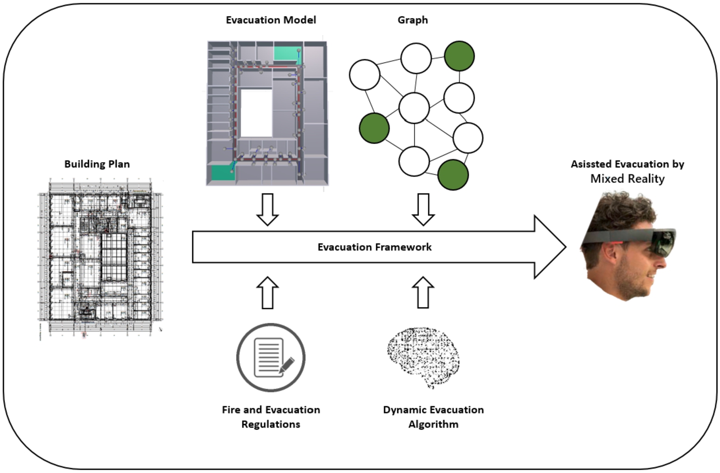
For assisted building evacuation or training building evacuations, we developed a framework that uses mixed reality technology to assist occupants in escaping buildings. The advantage of Mixed Reality (MR) over Virtual Reality (VR) is that the user is not visually separated from the real world as in VR. Thus, the user is still able to act in the real world and interact with virtual objects at the same time. This offers the possibility of enriching the real world with additional information. Thus, the user can interact with virtual and real objects at the same time. Figure 3 shows the system architecture of our approach. It consists of a building plan, evacuation model, graph, fire and evacuation regulations, dynamic evacuation algorithm, and mixed reality device (HoloLens). The system is based on the game engine Unity and is used in a Microsoft HoloLens. All components are utilized to generate an escape route which is displayed on the HoloLens.
Fig. 3.
Schematic representation of the system architecture of the mixed reality framework for building evacuation.
3.2.Building plan
The building plan contains all the dimensions to develop a model of the building. Alternatively, it is possible to complement the building plan with a BIM model in the next step to speed up the design of the model. Based on the dimensions, such as the width of a corridor, the capacity of a corridor is derived from the Fire and Evacuation Regulations in the next steps.
In our study, the official building plan of the Bielefeld University of Applied Sciences (Campus Minden) was used for the 3D modeling of the main building. The following parameters were used from the building plan to develop the Unity model:
– Dimensions of the base plate to create the footprint,
– Length and with of the walls,
– Doorway width,
– Floor width,
– Position of staircases.
Further information such as the material composition of the walls or ceiling is not considered in this work, as the focus of this work is on the assisted evacuation and not on a realistic fire spread.
3.3.Evacuation model
The evacuation model has been developed in the cross-platform game engine Unity3D and is preloaded in the HoloLens. The official building plan of the Campus has been taken as the basis of information to develop a model that is as realistic as possible concerning the geometric data. In detail, we first modeled the third floor to evaluate the algorithm, since this floor resembles an office building. The other floors contain, in addition to the offices, laboratories, seminar rooms, or libraries, where other maximum escape route lengths apply (Table 3). Since we have assumed that we will only use rooms with no or normal fire risk (up to 35 m). Figure 4(a) represents the model of the campus building. The green marked areas are staircases leading out of the building and are considered safe target areas. The gray areas represent offices and the corridors are marked in dark gray. The evacuation model is already used and successfully evaluated for the simulation of static and dynamic escape routes, cf. [24].
Fig. 4.
Evacuation model of the main building Bielefeld University of Applied Sciences (Campus Minden) and the realization of the mathematical graph.
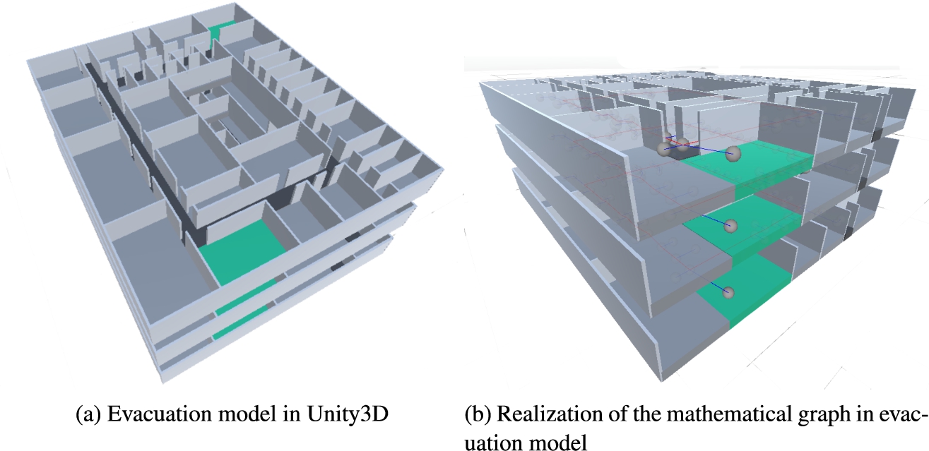
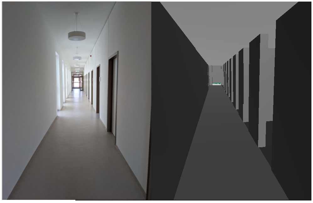
Figure 5 shows a comparison between the real building (left side) and the Unity model (right side). The most noticeable difference between the real building and the model is that there are no doors and windows in the Unity model. We deliberately did not model this because additional sensors would have had to be installed to query the door status and display it in the building plan, and the windows are for cosmetic purposes only. To query status, which could be done in future work.
Fig. 5.
Comparison of the real building and the unity model.
3.4.Graph
Mathematical graphs are commonly used to determine escape routes. In our building, a separate graph was created for each floor (Fig. 4(b)). Thus, the floors are evacuated independently of each other. The advantage is that each floor uses its own evacuation algorithm and the whole system is more robust against failures. If the system crashes on one floor, the other floors can still be evacuated.
As can be seen in Fig. 4(b), the graphs are not connected because according to [8], an evacuation is successful if the occupants are in a secured area (staircases, outside the building, etc.). To avoid the danger of an overcrowded staircase, it is possible to assign capacities to the staircases to ensure that the staircases are used as equally as possible.
The mathematical graph
Each node (V)contains the following parameters:
– Endnode
– Connections
Each edge (E) has the following parameters:
– Corridor width
– Evaluation value
– Connected to
3.5.Fire and evacuation regulations
In our work, we considered the basic technical rules of the Federal Institute for Occupational Safety and Health of Germany [8]. These technical rules fall into various categories such as the barrier-free design of workplaces, rules for windows, skylights and translucent walls, sanitary facilities, escape routes, emergency exit, rescue, and evacuation plans. As a basis for an efficient evacuation, it is important to integrate the technical rules from the categories, escape route, emergency exit, and evacuation plan into the calculation of the escape routes. An example is the capacity of an escape route, which depends on the width of the corridor. Table 2 shows an excerpt of the fire safety rules. The first column shows the width of the corridor and the second column shows the maximum number of people that can be led through the section. In our model/graph we made the assumption that
Table 3 shows the maximum length of an escape route, based on the hazard level of the room. The maximum escape route length for rooms without no or normal fire risk is 35 meters. The shortest prescribed escape route length is 10 meters and applies to rooms containing explosive substances. [8] has specified that the escape route length is the shortest distance measured as the linear distance from the most distant location to an emergency exit. Further provisions are not discussed in this work, but they can be found in [8].
Table 2
Maximum number of people per corridor section depending on the width [8]
| Corridor width in meter | Number of people (catchment area) |
| 0.857 | up to 5 |
| 1.00 | up to 20 |
| 1.20 | up to 200 |
| 1.40 | up to 300 |
| 2.40 | up to 400 |
Table 3
Maximum escape route length for the various danger ratings of the rooms [8]
| No. | Room characteristics | Maximum length |
| 1) | Rooms without or with normal fire risk, except rooms according to 2) to 6) | 35 m |
| 2) | Fire-prone rooms with automatic fire-extinguishing system | 35 m |
| 3) | Fire-prone rooms without an automatic fire-extinguishing system | 25 m |
| 4) | Rooms that are toxicant endangered | 20 m |
| 5) | Explosion-prone rooms, except rooms according to 6. | 20 m |
| 6) | Rooms containing explosive substances | 10 m |
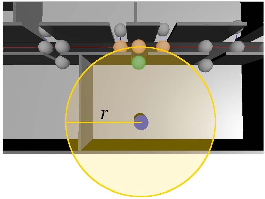
Fig. 6.
The Agent determines the start node in the Unity simulation based on a SphereCast.
3.6.Dynamic evacuation algorithm
The dynamic evacuation algorithm was developed to investigate the potential of intelligence-based evacuation. The system automatically detects the randomly placed fire in the building and incorporates this information to calculate the escape route. If a hazard is detected by the system, this information is stored in the graph. For this purpose, the position of the hazard is determined and the edge is marked as impassable in the graph. After converting the current building status (Building plan, Evacuation Model, Graph, and Fire and Evacuation Regulations) into a Unity scene representation, the algorithm is now able to determine the optimal evacuation path. To calculate the escape route, the algorithm has to find a start node. The determination of the start node for agents is done by a SphereCast. The SphereCast (spherical search in a defined radius) searches within the boundaries if it hits a node, it will be saved. In Fig. 6, the SphereCast is represented by a yellow highlighted area, and the agent is shown in blue. The orange-marked nodes are theoretically in the search radius. The two orange outer nodes may have a shorter escape route length than the orange node in the middle. Nevertheless, our algorithm invalidates the two outer orange nodes, because they are behind a wall and cannot be seen by the agent. This procedure prevents an agent from using an escape route that is not visible to him (unnatural behavior of people during an evacuation) and in the worst case, the agent could be shown an escape route with a starting point that is not accessible to the agent. The Orange node in the middle is also not the appropriate starting node. The system checks if more than one node was found. If yes, the distance (linear distance) is compared. The node nearest to the agent is used as the start node. In Fig. 6 the node is highlighted in green. This procedure ensures that the evacuation always starts at the nearest exit door from a room and not already in the hallway.
After computing a valid starting point, a shortest path algorithm is used as a basis for calculating the escape routes. Thereby, several different parameters are used as input for the graph optimization including
The
The
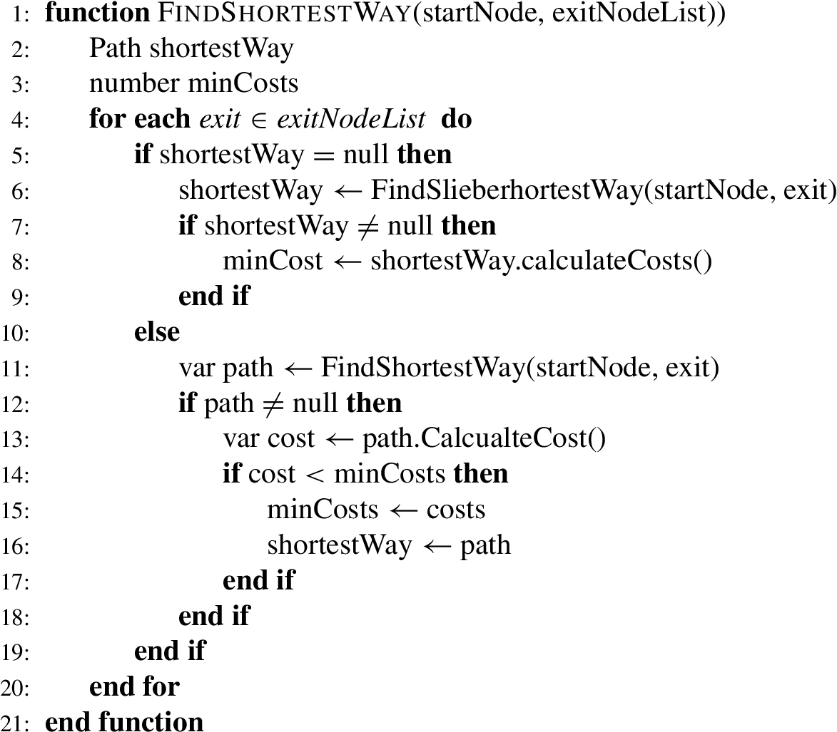
Algorithm 1 shows the process of calculating the best escape route in case of multiple emergency exits. First, it is checked whether an escape route has already been calculated and saved for the current position and hazard. If not, the best escape route from the user’s position to the first emergency exit in the list is calculated and set as the escape route. If there is already an escape route to another emergency exit, the newly calculated escape route to another emergency exit is compared with the current escape route. The better escape route with the lower costs is used as the escape route. This procedure is repeated for all emergency exits in the list.
Algorithm 1
Procedure for calculating the evacuation route with multiple exits
3.7.Localization via BLE beacons
For the indoor localization of the HoloLens (User), we choose Beacons technology because it is cheaper and easier to deploy than other wireless technology and many mobile and mixed reality devices already have the BLE interface. The position of the user in the building is required to display the escape route. A widely used technology is the Global Positioning System (GPS) and other satellite technologies. The problem with these systems is that they are not precise enough or in the worst case not able to receive signals inside the building (explicitly multi-story buildings and underground buildings), making the system unusable for an evacuation system.
Indoor localization is a separate research area that is not discussed in depth in this work, as it would exceed the scope. A common approach to determine the position in the building is based on the use of Bluetooth Low Energy Beacons [7,13,22]. There are various specifications for Bluetooth Beacons, in our work two commonly used standard specifications have been implemented.
The blukii Smart Beacon Go 500 Beacons are used which are based on Apple’s iBeacon standard. Bluetooth Beacons are usually compact transmitters that are placed inconspicuously in the environment. These transmitters send Bluetooth signals to undefined receivers at regular intervals. Both Beacon types transmit the following simple data packets, which are primarily used to uniquely identify the Beacon in question.
Table 4 lists the relevant information of the Beacons for indoor localization. The Universally Unique Identifier (UUID) is used to uniquely identify and recognize the Beacons. The Received Signal Strength Indication (RSSI) value indicates the signal strength between the Beacon and the end device. This is used in combination with the Signal Power (
Table 4
Listing of the information used for the indoor localization
| Specification | ||
| Data | Eddystone | iBeacon |
| UUID | yes | yes |
| RSSI | yes | yes |
| Signal power | yes (Tx power) | yes (Measured power) |
Fig. 7.
Overlap of the ranges of the beacons.
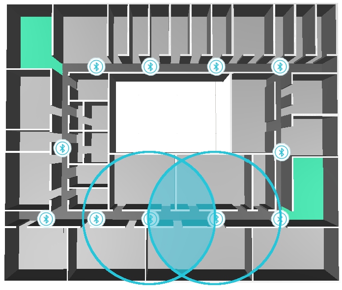
In our approach, we placed the Beacons at an equal distance from each other to reduce signal strength outliers. Figure 7 shows the building model and the positioning of the Beacons, which is necessary to set the current position of the user. The light blue circles represent the signal range of the Beacons. The distance between the Beacons is close enough so that the signal ranges of the Beacons overlap (light blue highlighted area in Fig. 7). This reduces the risk of not receiving a Beacon signal.
Fig. 8.
Visualization of the functioning of the localization algorithm during an evacuation.
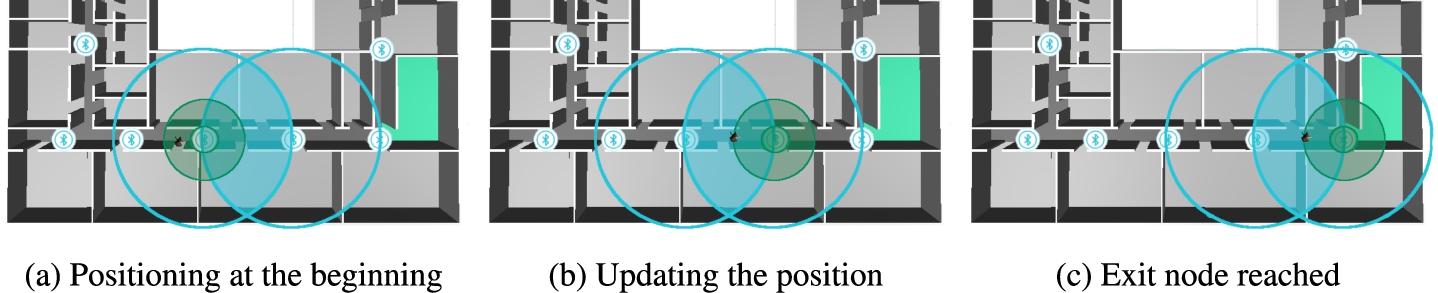
Figure 8 visualizes a section of the unity building model which visualizes step by step how the localization algorithm works during evacuation. For the representation of the Beacons, the blue-white circles with the Bluetooth symbol are used. The light blue circles in the three figures show the signal range of the Beacons and the light blue area shows the overlaps of the affected Beacons from which the user receives signals. An agent avatar was chosen to represent the user. The Beacon marked in green is the active Beacon with the closest distance to the user. The threshold (distance to the Beacon) for determining the closest Beacon is drawn as a highlighted green circle around the Beacon and can be set in Unity for each individual Beacon (see Section 3.8).
In the first step, all Beacon signals/information are collected to update the distances to the Unity already registered Beacons. The updating of the information is continuously done in the background to update the position of the user. Next, the system checks whether the user has moved below the threshold value of the respective Beacon (Fig. 8(a)). If this is the case, the user’s position is updated and is afterward located at the position of the Beacon. The user continues to move forward in the building and the Beacon list is permanently updated and checked if the threshold to another Beacon is undershot. In Fig. 8(b), the user undershoots the threshold of another Beacon and the algorithm would update the user’s position. If there are more than one Beacons in the surrounding area, the algorithm checks which Beacon is the nearest (distance comparison of the affected Beacons), and the position of the user is set to the same position as the closest Beacon.
In Fig. 8(c), the user undershoots the threshold to another Beacon located at the exit and the position of the user is set to the Beacon.
3.8.Assisted evacuation by mixed reality
We decided to use Microsoft’s HoloLens (1. Generation) mixed reality goggles for assisted evacuation of intelligent buildings. The advantage of the HoloLens is that it can be used wireless and the application runs directly on the hardware of the glasses. Thus, the user can move freely in large areas such as the Campus Building. The advantage of mixed reality is that the real world can be enhanced by virtual objects. This makes it possible to display information or provide assistance to a user while simultaneously moving around in the real world. Semi-transparent displays enable digital elements to be displayed in the user’s field of view. Usually, three-dimensional objects are displayed in such a way that it appears to the user as if they are in the real environment.
Figure 9 shows an occupant, assisted by the HoloLens, evacuating the building safely. The small picture in the picture shows the building model. The red dot on the map marks the position of the user in the building.
Figure 10 shows the user interface of the evacuation application on the HoloLens during an assisted evacuation. The total information available to the user while using the HoloLens is shown in Fig. 10(a) and 10(b). The grayed-out area represents the user’s entire field of view and the rectangle in the center shows the display area of the HoloLens. The figures represent an estimate of the ratios and are for visualization purposes only. The two display elements are not statically bound to the user’s field of view, which offers the advantage that the user does not have the elements permanently in the field of view during an evacuation and thus has a free view to the front.
Fig. 9.
Scenario of an occupant independently leaving the building with the assistance of the HoloLens.
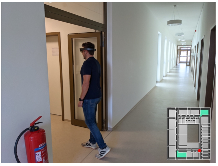
Fig. 10.
Visualization of the user information during an assisted evacuation.
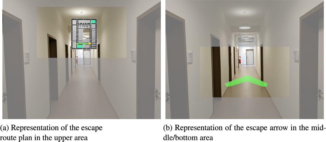
In our implementation, the user sees the map when looking up (Fig. 10(a)) and the navigation arrow when looking down (Fig. 10(b)). From the user’s point of view, these elements are located about one meter in front of the user in the space and are continuously visible. If the user looks slightly downwards, he can see the navigation arrow at approximately hip height. The map is bound to the user’s view because it keeps moving with the user on the horizontal. On the vertical, the map has a fixed position, just like the arrow, slightly above the user’s head height. Basically, if the user looks up, he sees the building map. If the user looks down, he sees the navigation arrow. Figure 10(a) shows the building map developed in Unity, with the user’s position (yellow dot) and viewing direction (yellow arrow) plotted. As soon as the user’s position changes, the position on the map is also updated. Additionally, the escape route for the user is drawn in green on the map. Figure 10(b) shows the navigation arrow pointing in the direction of the escape route. As soon as the user turns his or her head, the arrow automatically changes its orientation to the escape route.
Fig. 11.
The user turns and the navigation arrow and the orientation in the maps adjust automatically.
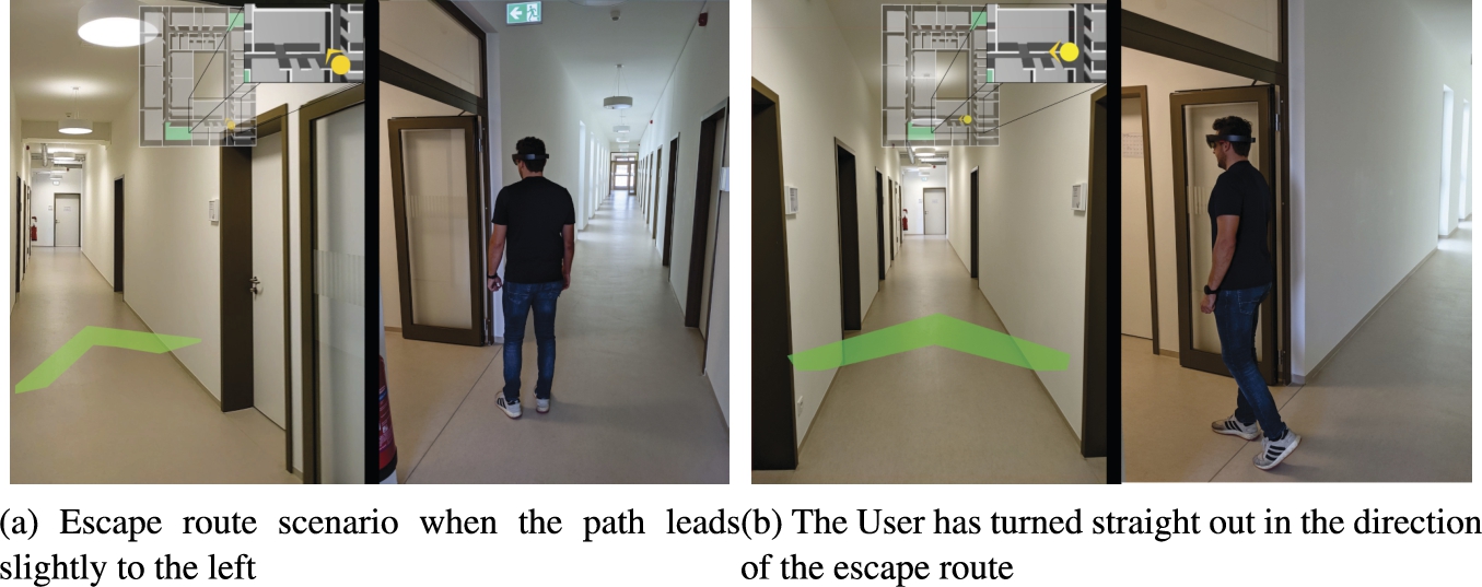
Figure 11 shows how the system responds to the user’s body rotation. The images represent all the information that the user can access. As already explained, the user does not have the navigation arrow and the map in the field of view at the same time because of the reduced field of view of the HoloLens. The figures are divided into two parts. The left side shows the user’s field of view (approximated) and the right side shows the user’s position in the building. The zoomed-in image of the current position is used for illustration purposes and is not displayed to the user by the HoloLens.
In Fig. 11(a), the user is looking obliquely into the corridor and the navigation arrow is also pointing slightly to the left to let the user know that the escape route is in that direction. The same can be seen in the zoomed map section. If the user turns further to the left (Fig. 11(b)), the navigation arrow and the orientation of the user on the map will also turn.
To determine the direction of the navigation arrow, the node closest to the user and part of the escape route are searched in the graph. In the next Step, the position of this node is determined and then the direction is determined. This is done by checking where the user is located on the map and where the node is located on the map. To convert the direction information from the map to the user’s view, the HoloLens must be initially calibrated. The difference in rotation between the user’s view and the user orientation on the map is determined. Based on this difference and the orientation on the map, the orientation of the navigation arrow is calculated. As a result, the navigation arrow constantly points to the next point on the escape route and the user can follow the arrow in a safe area.
4.Results
To evaluate our work, we examined two aspects. The first investigation focused on acceptance and how comfortable the user feels when using the prototype. The second experiment involved the evaluation of the static and dynamic system in a real building under laboratory conditions. For the evaluation, we chose a test group of five persons with no or only limited knowledge of the floor layout. Regarding the level of technical expertise, we assume a basic knowledge of smartphone handling such as swipe gestures and navigating through the menu. For this study, scenarios were developed that lead participants to a predefined room with a randomly placed fire. Thus, the scenario is hosted on the HoloLens and not on a server. The capacity of a corridor section will decrement when entering the section and increment when leaving the section. In our studies, capacity can be simulated by adding agents in the unity environment. The positioning is done as described with the beacons placed in the building.
Experiment 1: “User Acceptance”
In our first experimental setup, the glasses were already switched on and calibrated. Thus, the glasses were directly ready for use. In the beginning, we explained that we want to investigate whether the glasses help the user to evacuate a building. The help elements (navigation arrow and building plan) were not explained in advance and the user was asked to put on the glasses and find his way around. This way, each person only needed to familiarize himself with the HoloLens and not seek an escape route. Subsequently, participants were asked to name the number of elements and describe them according to their understanding. In addition, the subjects were allowed to walk through the building with the glasses and see how the system behaved. After five minutes, each user was asked to name the appearing elements in the glasses plus further free comments on the overall usage.
After a short familiarization period, the test persons found their way around the information well, and each user was able to correctly name the two augmented elements, i.e. the navigation arrow and the map. In the survey emerged that the arrow should have a stroke in the middle and if the user looks a little further up (straight ahead), the arrowhead is further forward and the stroke should be longer. Furthermore, it was suggested that there should be the possibility to zoom in on the building map for a more detailed view of the current position.
Experiment 2: “static vs. dynamic algorithm in real-world scenarios”
In the second experiment, the static escape route visualized by the escape route signs located in the building was compared with the dynamic escape route algorithm. In our previous work [24], we already examined both algorithms for evacuation time and total occupant distance, and found that the dynamic algorithm allows for a more efficient building evacuation. Our goal in this experiment is now to confirm these results also in a real-world scenario. Thereby, the HoloLens is used to provide information of the dynamic escape route to the user. To allow subjects to use more than just the normal escape route, we declared random rooms on the floor as emergency exits. In a first step, the test persons had to find the way from A to B with static signs, manually placed in addition to the existing signs in the building. In a second step, the persons were then asked to find escape routes with the assistance of the HoloLens.
We found that following escape routes and finding emergency exits was faster with the HoloLens than with the static sign. The subjects found the given exit rooms without problems with the HoloLens, whereas for the static system the subjects looked around more often to find the way. In addition, the goggles allowed more comfort compared to a smartphone during an evacuation, because the subject has the hands free and does not have to look at the smartphone display. We are aware that during a fire, not everyone in the building is walking around with a HoloLens. But thinking into the future, the system can be integrated into more compact smarter everyday devices like Google Glass. Furthermore, the system can be used to train dangerous situations. For example, where do people look most often. The HoloLens enables the display of virtual hazards (we are currently working on this), which makes the simulation of hazards much easier and more flexible than, for example, setting up fog machines.
Currently, our prototype is limited to one floor. In the next steps, this limitation could be solved, for example, by adding another node type (floor connection). If we connect multiple floors, we would have to re-evaluate the localization and adjust the distances of the beacons if necessary. It might happen that a beacon signal from another floor sends stronger signals than a beacon from the user’s floor if the distance between the individual beacons is too large. As a result, a wrong escape route could be presented to the user. Furthermore, the HoloLens has to be calibrated at the beginning of use in order to display the correct cardinal direction.
5.Conclusion
In this work, we developed an interactive evacuation tool that can be used for assisted evacuation of buildings or training and analyzing evacuation scenarios. The system is based on the game environment Unity. In our study, we found that our dynamic algorithm evacuates buildings more efficiently than a static system. As a result, we added a mixed reality component to our system, to evaluate our previously computer-simulated results in real scenarios.
The HoloLens is used to display the escape routes and Bluetooth beacons are used to determine the position in the building. Based on the position, an individual escape route is dynamically created, which led around blocked paths or hazardous areas. The prototype shows the user’s position on a map as well as the escape route and the layout of the surrounding rooms. Furthermore, the user is shown a directional arrow that leads along the escape route. This information is displayed directly in the user’s field of view using the HoloLens AR glasses and is available to the user during the evacuation.
In a manual expert study, we found that our prototype offers a good way to display security-related information. Furthermore, it must be investigated how the initial learning phase can be made quicker for people who have never used AR glasses before. Overall, a combination of the different sources of information and the technologies used has resulted in a good prototype that assists in the evacuation of buildings.
As a next step, we plan to add additional gestures to the HoloLens handling, such as zooming in on the map. Furthermore, an analysis of larger evacuation scenarios with more persons to test interactions between participants is currently underway. In addition, a central server and floor connections unit is planned, via which the Scenario can be modified in real-time.
Conflict of interest
None to report.
Notes
1 Website [18].
References
[1] | J. Ahn and R. Han, An indoor augmented-reality evacuation system for the smartphone using personalized pedometry, Human-centric Computing and Information Sciences 2: (1) ((2012) ), 18. doi:10.1186/2192-1962-2-18. |
[2] | W. Bai, Y. Huo, G.W. Zou and Y. Gao, Simulation of fire evacuation in a high-rise office building, in: IEEM 2015, IEEE, Piscataway, NJ, (2015) , pp. 1704–1708. doi:10.1109/IEEM.2015.7385938. |
[3] | D. Biedermann and E. Sebastian, Is macroscopic resolution enough? – A study about the use of different spatial scales in pedestrian dynamics, in: 28. Forum Bauinformatik, IEEE, (2016) , pp. 1–12. |
[4] | T. Bittner and C.-D. Thiele, Untersuchung des Potenzials der Unity-Engine für Entfluchtungssimulationen auf Basis der RiMEA, Forum Bauinformatik 31: ((2019) ), 265–273. |
[5] | V.J. Cassol, J.O. Brasil, A.B. Fortes Neto, A. Braun and S.R. Musse, An approach to validate crowd simulation software: A case study on CrowdSim, in: 2015 14th Brazilian Symposium on Computer Games and Digital Entertainment (SBGames), IEEE, (2015) , pp. 192–203. doi:10.1109/SBGames.2015.11. |
[6] | L.-W. Chen, J.-H. Cheng and Y.-C. Tseng, Evacuation time analysis and optimization for distributed emergency guiding based on wireless sensor networks, in: 2012 International Conference on Connected Vehicles and Expo (ICCVE), IEEE, (2012) , pp. 130–135. doi:10.1109/ICCVE.2012.32. |
[7] | A. Depari, A. Flammini, D. Fogli and P. Magrino, Indoor localization for evacuation management in emergency scenarios, in: 2018 Workshop on Metrology for Industry 4.0 and IoT, IEEE, (2018) , pp. 146–150. doi:10.1109/METROI4.2018.8428343. |
[8] | Federal Institute for Occupational Safety and Health, ASR A2.3 escape routes and emergency exits, escape and rescue plan, 2017. |
[9] | G. Fernández, Design and implementation of an agent-based crowd simulation model for evacuation of university buildings using Python, Dissertation, Universidad Politéca de Madrid, Madrid, Spain, 2017. |
[10] | D. Guo, C. Gao, W. Ni and X. Hu, Max-flow rate priority algorithm for evacuation route planning, in: 2016 IEEE First International Conference on Data Science in Cyberspace (DSC), IEEE, (2016) , pp. 275–283. doi:10.1109/DSC.2016.50. |
[11] | A. Kulakowski and B. Rogala, Agent simulation of the evacuation process from a building during a fire, in: 2017 12th International Scientific and Technical Conference on Computer Sciences and Information Technologies (CSIT), IEEE, (2017) , pp. 385–388. doi:10.1109/STC-CSIT.2017.8098811. |
[12] | N. Li, N. Sun, C. Cao, S. Hou and Y. Gong, Review on visualization technology in simulation training system for major natural disasters, Natural Hazards (Dordrecht, Netherlands) 112: (3) ((2022) ), 1851–1882. doi:10.1007/s11069-022-05277-z. |
[13] | X.-Y. Lin, T.-W. Ho, C.-C. Fang, Z.-S. Yen, B.-J. Yang and F. Lai, A mobile indoor positioning system based on iBeacon technology, in: Annual International Conference of the IEEE Engineering in Medicine and Biology Society. IEEE Engineering in Medicine and Biology Society. Annual International Conference, (2015) , 4970–4973. doi:10.1109/EMBC.2015.7319507. |
[14] | S. Nahavandi, L. Wei, J. Mullins, M. Fielding, S. Deshpande, M. Watson, S. Korany, D. Nahavandi, I. Hettiarachchi, Z. Najdovski, R. Jones, A. Mullins and A. Carter, Haptically-enabled VR-based immersive fire fighting training simulator, in: Intelligent Computing – Proceedings of the Computing Conference, Springer, Cham, (2019) , pp. 11–21. doi:10.1007/978-3-030-22871-2_2. |
[15] | R. Peacock, G. Forney, P. Reneke, W. Jones and R. Portier, CFAST: The consolidated model of fire growth and smoke transport, 1993. doi:10.6028/NIST.tn.1299. |
[16] | A. Rahouti, R. Lovreglio, C. Dias and S. Datoussaïd, Simulating assisted evacuation using Unity3D, in: International Conference on Traffic and Granular Flow, (2017) , pp. 265–275. doi:10.13140/RG.2.2.23031.93609. |
[17] | J. Ribeiro, J.E. Almeida, R.J.F. Rossetti, A. Coelho and A.L. Coelho, Using serious games to train evacuation behaviour, in: 7th Iberian Conference on Information Systems and Technologies (CISTI 2012), IEEE, (2012) , pp. 1–6. |
[18] | RiMEA e.V., RiMEA e.V, 2021. https://rimea.de/. |
[19] | C. Rogsch, Simulationsmethoden für Brandschutz und Evakuierung – Grundlagen – Anwendung – Erweiterung, Ph.D. Dissertation, Universität Wuppertal, Fakultät für Maschinenbau und Sicherheitstechnik Dissertationen, 2012. |
[20] | H. Schieber, C. Kleinbeck, C. Pradel, L. Theelke and D. Roth, A mixed reality guidance system for blind and visually impaired people, in: 2022 IEEE Conference on Virtual Reality and 3D User Interfaces Abstracts and Workshops (VRW), IEEE, [S.l.], (2022) , pp. 726–727. doi:10.1109/VRW55335.2022.00214. |
[21] | S. Sharma, S.T. Bodempudi, D. Scribner, J. Grynovicki and P. Grazaitis, Emergency response using HoloLens for building evacuation, in: Virtual, Augmented and Mixed Reality, Springer, Cham, (2019) , pp. 299–311. doi:10.1007/978-3-030-21607-8_23. |
[22] | K. Shimizu and D. Kushida, Evacuation guidance system using beacon information and Dijkstra’s algorithm, in: 2021 IEEE 3rd Global Conference on Life Sciences and Technologies (LifeTech), IEEE, (2021) , pp. 319–323. doi:10.1109/LifeTech52111.2021.9391946. |
[23] | T. Tabirca, K.N. Brown and C.J. Sreenan, A dynamic model for fire emergency evacuation based on wireless sensor networks, in: 2009 Eighth International Symposium on Parallel and Distributed Computing, IEEE, (2009) , pp. 29–36. doi:10.1109/ISPDC.2009.33. |
[24] | T. Wächter, J. Drögemeier and M. Hoffmann, Simulation of static and dynamic evacuation algorithms in intelligent buildings using Unity3D, in: 2021 17th International Conference on Intelligent Environments (IE), IEEE, (2021) , pp. 1–7. doi:10.1109/IE51775.2021.9486536. |
[25] | T. Wächter and M. Hoffmann, Dynamic evacuation route system, in: Organic Computing: Doctoral Dissertation Colloquium, Vol. 13: , Kassel University Press, (2018) , pp. 196–209. |
[26] | T. Wächter, J. Rexilius, M. Hoffmann and M. König, Intelligent building evacuation under consideration of temporary events and dynamic fire propagation, in: 2022 18th International Conference on Intelligent Environments (IE), 6/20/2022–6/23/2022, IEEE, (2022) , pp. 1–8. doi:10.1109/IE54923.2022.9826762. |
[27] | Z. Weifang and C. Qiang, Implementation of intelligent fire evacuation route based on Internet of things, in: Proceedings of 2015 IEEE Advanced Information Technology, Electronic and Automation Control Conference (IAEAC 2015), B. Xu, ed., IEEE Press, Piscataway, New Jersey, (2015) , pp. 934–938. doi:10.1109/IAEAC.2015.7428693. |
[28] | Y. Zhang and S. Li, Distributed biased min-consensus with applications to shortest path planning, IEEE Trans. Automat. Control 62: (10) ((2017) ), 5429–5436. doi:10.1109/TAC.2017.2694547. |


