You are viewing a javascript disabled version of the site. Please enable Javascript for this site to function properly.
Go to headerGo to navigationGo to searchGo to contentsGo to footer
In content section. Select this link to jump to navigation

In-beam superfluid-helium ultracold neutron source for the ESS

Abstract

This paper discusses design principles and possible performances of an “in-beam” ultracold neutron (UCN) source for the European Spallation Source (ESS). The key components of the proposed neutron delivery system are nested-mirror optics (NMO), which image the bright neutron emission surface of the large liquid-deuterium moderator, studied within the HighNESS project, onto a remotely located superfluid-helium converter. Bandpass supermirrors, with optional polarization capability, enable the selective transport of those neutrons that are most effective for UCN production, exploiting the single-phonon conversion process that is possible for neutrons having wavelengths within a narrow range centered on 8.9A˚. NMO are capable of extracting and refocusing neutrons with small transport losses under the large solid angle available at the ESS Large Beam Port (LBP), allowing the converter to be placed far away from the high-radiation area in the ESS shielding bunker, where the source stays accessible for trouble-shooting while facilitating a low-background environment for nearby UCN experiments. Various configurations of the beam and converter are possible, including a large-volume converter – with or without a magnetic reflector – for a large total UCN production rate, or a beam focused onto a small converter for highest possible UCN density. The source performances estimated by first simulations of a baseline version presented in this paper, including a saturated UCN density on the order of 105cm3, motivate further study and the development of NMO beyond the first prototypes that have been recently investigated experimentally.

1.Introduction

Intense sources of ultracold neutrons (UCN) are a prerequisite to a variety of projects at the high-precision frontier of low-energy particle physics. Among these experimental efforts are searches for a non-vanishing permanent neutron electric dipole moment (EDM), accurate measurements of the neutron beta-decay lifetime and asymmetries, and searches for dark matter and dark energy using gravitational spectroscopy methods [6].

Most modern UCN sources are of the “superthermal” type, first proposed in 1975 by Golub and Pendlebury [11]. There, in contrast to UCN production by neutron moderation, cold neutrons are “converted” to UCN by imparting nearly their entire kinetic energy to elementary excitations – most commonly phonons – of the source medium in single scattering events. When the medium is kept at low temperature, up-scattering of UCN back to higher energies is suppressed, enabling UCN densities larger than those possible by neutron thermalization in the medium. Shortly after the 1975 proposal, superfluid 4He (He-II) and solid deuterium (SD2) were identified as particularly suitable source media for neutron conversion [9,12], and have since been applied in various existing UCN sources.

More recently, solid α-oxygen [14,23] and solid α-15N [33] have been investigated as possible UCN production media. Like in He-II and SD2, neutron conversion in these media relies on coherent excitations, magnons and phonons in the former, and only phonons in the latter case. An alternative method of UCN production would employ a gradual slowdown of neutrons via multiple incoherent inelastic scattering events that excite local low-energy modes. One such recently-considered moderation scheme proposes to employ the zero-field splitting of the magnetic triplet state of molecular oxygen to cool neutrons in a multi-step cascade of constant energy decrements [51]. Realization of this scheme might place the paramagnetic molecular oxygen as a guest within the interstices of a host solid, such as fully deuterated clathrate hydrate, a weakly-neutron-absorbing heavy-water network. Assessment of the capabilities of such materials for the production of UCN and very cold neutrons (VCN) is a topic of current research within the HighNESS project [34], and is complementary to work on He-II based UCN sources.

While the exploration of new media for UCN production, described in the previous paragraph, is still at an early stage of development, the concept of an “in-beam” UCN source based on He-II as a well-established conversion medium is rather mature nowadays. It is the purpose of the present paper to point out possibilities for a competitive in-beam UCN source at the European Spallation Source (ESS), adapted to take advantage of a high-intensity liquid-deuterium (LD2) moderator accessible under large solid angle through a wide opening in the shielding monolith, aptly-named the Large Beam Port (LBP). Details of the relevant ESS infrastructure may be found in Ref. [50].

2.Superfluid-helium converters: “in-pile” or “in-beam”?

Unique among all possible UCN production materials, 4He is the only stable nuclide with vanishing neutron absorption cross section. Consequently, isotopically pure He-II-based converters enable UCN storage lifetimes τ several orders of magnitude larger than are possible in all other media. This makes it possible to gradually build up a high density of UCN in the converter, which may then be used to great advantage in a variety of experimental situations.

The upper limit to τ is set by the beta decay mean free neutron lifetime τβ880s. In order to achieve storage times in superfluid helium that are of this order, it is necessary to suppress strongly temperature dependent neutron up-scattering. For He-II at temperatures T1K, the rate constant for up-scattering is [8,10]

(1)τup1(T[K])7100s.
Hence, for T0.7K, neutron loss due to up-scattering is smaller than that due to beta decay, and quickly becomes negligible at temperatures further lowered by one or two tenths of a Kelvin.

Broadly speaking, there are two possible implementations of He-II-based neutron converters. The first places the He-II “in-pile” in the intense field of neutrons pre-moderated by a cold source located near a primary neutron source, such as the core of a nuclear reactor or a spallation target [20,26,40]. This is the standard location for neutron cooling devices, in which the large cold-neutron flux leads to a high UCN production rate. Unfortunately, the large heat load on the converter from neutrons and gamma radiation makes it unrealistic to maintain temperatures below 1K near a high-power primary neutron source, even when a powerful cryogenic plant is available [22,39]. Therefore, in this configuration, the converter is directly connected to an extraction guide, from which UCN stream continuously, delivering a high steady flux of UCN either to an experiment operated in a flow-through mode or to several storage experiments in a time-shared mode [43]. However, it should be noted that, if the primary neutron source is not too strong [41], temperatures well below 1K are still possible in-pile. In such cases, the UCN source can partly compensate for a lower primary neutron source power by making use of a UCN valve at the extraction guide entrance to build up, or accumulate, a high UCN density in the converter [32,54].

In fact, such an accumulation concept, first pointed out in Ref. [12], is the basis for the second possible implementation of a He-II-based UCN source, in which the converter is irradiated “in-beam” by a beam of cold neutrons while situated far away from the hot zone of the primary source. In this configuration, the significantly lower heat load on the converter makes temperatures below 0.7K feasible without excessive cryogenic efforts. Despite the smaller solid angle under which the cold neutron beam can irradiate the converter, and hence the lower UCN production rate, UCN densities accumulated in-beam can compete with in-pile converter densities.

As will be discussed in greater detail in the next section, this competitiveness requires the suppression of neutron absorption and UCN losses due to wall collisions to the same degree as up-scattering. However, the complexity of this task is substantially reduced for a converter placed far from the primary neutron source, where its accessibility enables not only adaptation of the neutron transport system and UCN source to match the specific needs of an experiment, but makes it possible to supply UCN thereto with a relatively short guide.

In fact, a UCN guide can even be rendered unnecessary in the extreme variant of an in-beam source in which the experiment is immersed in the superfluid-helium of the converter itself. This strategy avoids UCN transport losses and, in some cases, offers additional advantages, using the helium either as a neutron detection medium, a means to increase resistivity and prevent electrical breakdown in neutron EDM searches, or a combination of the two [1,17,46]. The application of these concepts to multiple UCN storage chambers is also discussed in Ref. [5].

3.Basic principles of an in-beam UCN source

There are three main components to an in-beam UCN source: a cold neutron moderator, a neutron optical delivery system (NODS), and a converter vessel, filled in this case with He-II. The problem of optimizing the UCN production according to a particular set of desired characteristics requires a careful consideration of not only the many parameters describing these three components, but also the interplay between them. The present section is intended to serve as a point of entry into this problem, and will focus on a simplified picture of the in-beam source in order to discuss the concepts that are key to UCN production. Here, we will mainly consider the case in which one desires a high density of UCN in the source. The discussion is ordered proceeding in the upstream direction, that is, starting from the converter surface upon which cold neutrons are incident and working back toward the moderator.

Let us first consider the cold neutron beam incident on the converter. The parameters thereof relevant to UCN production are the converter surface area Aconv, which we take to be planar and perpendicular to the beam axis, and the “brilliance” of neutrons incident upon it, bconv (units of s1cm2sr1A˚1). After multiplying this latter quantity by the differentials dΩ and dλ, one obtains the number of neutrons per second and per unit area with wavelengths between λ and λ+dλ and in the solid angle dΩ about a particular direction that penetrate a unit area perpendicular to this direction. In general, the brilliance varies as a function of wavelength, direction, and position, and can be used to define the “flux spectrum” (units of s1cm2A˚1) at the converter by integrating over the solid angle Ωconv of all incident neutrons, that is,

(2)(dΦdλ)conv=bconvdΩ,
which depends only on wavelength and position. One is interested in this quantity because, in order to construct a high-density UCN source, one seeks to maximize the area-averaged, or “mean”, incident flux spectrum at the converter surface
(3)(dΦdλ)conv=1Aconv(dΦdλ)convdAconv.

Let us consider the differential surface element dAconv at a particular position on the converter surface and restrict our attention to all neutrons of a given wavelength that are incident there from a particular direction. At the moderator surface, which we also take to be planar and perpendicular to the beam axis, there is a corresponding position and differential surface element dAmod – not necessarily equal to dAconv – from which are emitted all those neutrons that are capable of being transported by the NODS to dAconv. Let us call bmod the brilliance of such neutrons, and make the approximation that they are uniformly distributed within the solid angle Ωmod, which is small in practice. In this case, one may show that Liouville’s theorem, which dictates that the phase space density of a free neutron beam cannot increase, implies that

(4)(dΦdλ)convΩconvΩmod(dΦdλ)mod,
where we have used
(5)(dΦdλ)mod=bmoddΩ=Ωmodbmod.

Although not true in general, for the special case that (dΦ/dλ)mod is uniform over the moderator surface, the flux spectra in Eq. (4) can be replaced by their area-averages. Equation (4) highlights the purely geometrical effect of the NODS in controlling the ratio Ωconv/Ωmod to potentially change the mean flux spectrum at the converter surface compared to that at the moderator. This point is important because, in comparing the performance of candidate NODS with different geometries, one should be careful to distinguish such geometric effects from other sources of loss, which can be included in the above formulation as

(6)(dΦdλ)conv=ϵtrΩconvΩmod(dΦdλ)mod.
In this way, 0ϵtr1 accounts for any intensity reducing effects, such as imperfect reflections from the NODS surface or surfaces, and absorption or scattering over the neutron flight path.

Before continuing along the main line of our discussion, we would like to address one point that may have occurred to the reader. In general, those portions of the flux spectrum at the physical emission surface of the moderator that are not transported to Aconv by the geometry of the NODS may nevertheless reach the plane of the converter surface. In principle then, one could capture more of the total rate of incident neutrons by increasing the size of Aconv. However, as we shall see later, increasing Aconv generally results in a decrease of the mean flux spectrum at the converter, and thus in an unwanted reduction in the UCN density of the source.

Having thus outlined the cold neutron beam transportation, let us now consider UCN production in the converter vessel, and briefly describe the typical fashion in which it is used. As was previously mentioned, the basis for the implementation of the in-beam source is the accumulation of UCN therein under irradiation by the cold neutron beam. In typical configurations, the accumulated ensemble of UCN is used by releasing it as needed to an experiment through a UCN valve, enabling cyclical operation of the source. This mode is particularly suitable for UCN storage experiments, which often detect in some way those neutrons that remain after storage. Thereafter, a new ensemble of accumulated UCN is released from the replenished source, and the cycle is repeated until the desired sensitivity to the effect being investigated is reached.

The time evolution of the build-up of UCN density in the source under irradiation by cold neutrons follows from the rate equation including both the UCN production and loss, and is

(7)ρUCN(tacc)=ρsat(1etacc/τ),
where tacc is the accumulation time under irradiation and τ is the storage lifetime of UCN in the closed converter. After sufficiently long tacc, the UCN density approaches its asymptotic value
(8)ρsat=pτ,
which is the product of the storage lifetime and p, the UCN production rate density (units of s1cm3). Thus, one wishes to maximize the product of p and τ in order to obtain the highest possible UCN density in the source.

Let us first consider maximization of τ. Its inverse, the “rate constant” for UCN loss, is given by

(9)τ1(E,T)=τβ1+τup1(T)+τwall1(E)+τ3He1.
In addition to the previously discussed beta decay and up-scattering losses, this quantity also contains contributions τwall1 from collisions of UCN of energy E with the converter walls, and τ3He1 from absorption by 3He impurities. Suppression of wall losses requires a vessel “tight” against UCN leakage, typically made of or coated with a weakly absorbing material having a large neutron optical potential; see, e.g., Ref. [13] for more details. For polarized UCN, wall losses can be greatly reduced, and even avoided, by surrounding the converter vessel by a multipole magnet [55]; the SuperSUN UCN source project at the ILL, for example, foresees such a device in its second phase [3]. Neutron absorption by 3He impurities can be suppressed to a negligible level by using a superleak [48,56] or through the heat flush technique [27]. The work described in Ref. [17] has experimentally demonstrated that storage lifetimes of many hundreds of seconds may indeed be achieved in a closed He-II converter surrounded by a multipole magnet.

While maximization of τ concerns primarily the converter vessel itself, maximization of p also entails a consideration of the moderator and NODS. There are two mechanisms that contribute to the production rate, i.e., p=pI+pII. The dominant “single-phonon” process (pI), in which a cold neutron with initial energy in a narrow range centered on E1.04meV, corresponding to wavelength λ8.9A˚, imparts nearly all its energy to the converter medium by exciting a single phonon. The resulting neutron can be stored if its final energy is less than the “well depth” Vconv, which is the difference in the neutron optical potentials of the converter walls and the He-II. Taking the walls to be beryllium, the well depth is Vconv=VBeVHe233neV, and the production of storable UCN is kinematically allowed for cold neutrons within an interval of width ΔE30μeV centered on E, corresponding to a full range width of Δλ/λ1%. Contributions from all ΔE result in a UCN production rate density of [36]

(10)pI5.0×1016×(dΦdλ),(dΦdλ)=(dΦdλ)|λ=λ,
which makes clear the previously stated goal of maximizing the average of (dΦ/dλ) at the converter. The numerical factor in Eq. (10) scales with Vconv3/2 as a consequence of the phase space available to the UCN, and is the product of quantities derived from inelastic neutron scattering data. A detailed numerical treatment of UCN production by the single-phonon mechanism can also be found in Ref. [47]. The second contribution to UCN production (pII) accounts for inelastic scattering of more energetic cold neutrons, E>E, and involves several phonons. Such “multi-phonon” processes occur over a wider range of the neutron spectrum, but, for typical cold beams delivered by neutron guides, contribute less than 30% to the total UCN production [2,21,35].

When an experiment installed at the UCN source is filled, as described above, by releasing the UCN accumulated in the converter, the UCN therein are subsequently diluted over the combined volume of the source, guides, and experiment. A larger source volume is therefore often desirable. However, increasing the source volume, in which UCN production takes place, typically reduces the mean UCN production rate density. Nevertheless, the resulting larger total UCN production rate may still increase the total number of UCN that finally arrive in the experiment. In such a situation, the high transparency of He-II for cold neutrons is very helpful, as it enables an increase of the total UCN production rate simply by elongating the converter vessel along the beam direction. Depending on the incident solid angle Ωconv and the overall length of the converter Lconv, dilution of the UCN production rate density p due to beam expansion can be minimized by lateral confinement of the incident beam in the source through the use of a neutron guide of constant cross section Aconv running down the converter length. In general, the total UCN production rate in such a system follows from integration of p over the converter volume, and is

(11)P=pdxdA=Aconvϵconv(λ)(dΦdλ)convex/Λconv(λ)dxdλ,
where ϵconv(λ) is a UCN conversion efficiency per wavelength. In passing to the second equality, we have integrated over Aconv and have assumed that the mean flux spectrum drops off exponentially from the value at the converter surface with attenuation length Λconv(λ).

Limiting the incident flux spectrum to the previously discussed narrow range of wavelengths centered on 8.9A˚ greatly reduces the heat load and background associated with neutrons that anyway have lower efficiency to convert to UCN [31]. Considering then only single-phonon UCN production, the volume-averaged UCN production density is

(12)PIAconvLconv5.0×1016×ΛLconv(1eLconv/Λ)(dΦdλ)conv.

In this expression, we have replaced Λconv(λ) by Λ(λ), which is the mean free path for a neutron in He-II alone. At 8.9A˚, Λ=Λ(λ)16.6m [42], so that even a converter several meters in length is “short” in the sense that LconvΛ. Thus, the attenuation factor 1Lconv/(2Λconv) stays close to unity, enabling a large source volume, and hence large PI, at marginal cost in UCN density. One could also consider forgoing the technical complication of immersing a neutron guide within the He-II converter by increasing the converter vessel cross sectional area along the beam direction, thus allowing for beam expansion. This might, however, reduce the number of UCN in the experiment, and one should also note that the UCN extraction rate from the source is proportional to the reciprocal of the converter vessel volume. Interestingly, inclusion of the PII contribution to P does very little to improve the total rate or the UCN density; in long converters, PII falls significantly below the aforementioned 30% observed in short converters due to a strong increase in the scattering cross section at smaller wavelengths, resulting in Λ(λ)Λ [42].

Finally, let us examine the conceptually simplest NODS, analyzed in Ref. [31], in which the converter is directly connected to the moderator by a neutron guide of constant cross section Aguide=Aconv=Amod. The glancing angle θ of neutrons of wavelength λ transported in the guide is limited by the “critical angle” θc=θc(λ), above which the probability of reflection from the guide surface quickly drops to zero. When θc is small, the dependence can be expressed to good approximation as

(13)θc=mκλ,
where m is a dimensionless factor that depends on the mirror coating, and κ=0.099/A˚=0.00173rad/A˚ is a constant that is characteristic of natural Ni, a mirror surface commonly-used in early neutron guides. Supposing that all neutrons of wavelength λ with glancing angles less than θc have unit probability of being reflected, the solid angle of neutrons emerging from either end of a guide due to an isotropic point source placed inside the guide and far from its ends may be shown to be
(14)Ω(λ)=γθc2m2λ2,
where the factor γ accounts for the geometry of the guide cross section; e.g., γ=4 and γ=π for rectangular and circular guide cross sections, respectively. While modern multi-layer “supermirrors” [15,28,45] can achieve up to m=8 [44], Eq. (14) overestimates their ability to transport solid angle. In broadband supermirrors, this is due to the fact that the reflectivity drops (approximately linearly) for glancing angles above κλ, which exacerbates losses with multiple reflections in long guides. The next section describes more sophisticated NODS that offer not only superior performance in comparison to straight guides, but also greater versatility in adapting the cold neutron beam to the UCN source.

4.Advanced neutron delivery systems for in-beam UCN sources

While transportation of the solid angle Ω(λ) in Eq. (14) concerns a point source inside the guide volume, in reality, the guide entrance is separated from the moderator emission surface by a gap. As the physical extent of the moderator surface is finite, increasing this gap will eventually result in the guide entrance ceasing to be “fully illuminated”, i.e., irradiated by the source from all directions in which neutrons can be transported at a given wavelength, at which point the transported solid angle becomes limited by geometry rather than by θc(λ). For a UCN source that converts primarily 8.9A˚ neutrons, the critical angle of interest is

(15)θc=m×0.881=m×0.0154rad,
corresponding to a beam that, for every meter of unguided travel, expands in width by m×3.08cm, and whose projection from the guide entrance back to the moderator must lie within the emission surface in order for the guide to be fully illuminated at 8.9A˚. This requirement cannot be fulfilled if one uses large-m guides to transport neutrons from the para-hydrogen moderator at the ESS [49]. There, in order to avoid obstructing a direct view at neighboring beamlines of the moderator surface, which is only 3cm tall, neutron optical elements are restricted from being placed closer than 2m from the moderator. This difficulty provided the original impetus for the development of elliptic nested mirror optics (NMO) [53], which can be placed far from both the moderator and target and still accept neutrons within a broad angular range. However, the advantage of a larger emission surface was eventually recognized, leading to the conception of the large LD2 moderator, currently being studied within the HighNESS project. Additionally, the installation of only a single instrument is now foreseen in the direction of the LBP, enabling beam extraction to start closer to the moderator. Nevertheless, an NMO neutron extraction system offers several advantages over neutron guides.

Fig. 1.

Schematic of an elliptic nested mirror optical (NMO) system. M and M’, separated by 2f, are the common foci of a set of ellipses, one of which is indicated by a dashed line. The mirror surfaces are formed by truncating the ellipses to the common length l. See Ref. [53] for details of the mathematical construction. The two types of symmetry about the optical axis of the NMO are indicated in the upper corners; the views show the NMO surfaces projected onto a surface normal to the optical axis z. Throughout the paper, x denotes the horizontal direction transverse to z, and y the vertical direction.

Schematic of an elliptic nested mirror optical (NMO) system. M and M’, separated by 2f, are the common foci of a set of ellipses, one of which is indicated by a dashed line. The mirror surfaces are formed by truncating the ellipses to the common length l. See Ref. [53] for details of the mathematical construction. The two types of symmetry about the optical axis of the NMO are indicated in the upper corners; the views show the NMO surfaces projected onto a surface normal to the optical axis z. Throughout the paper, x denotes the horizontal direction transverse to z, and y the vertical direction.

The basic idea of an elliptic NMO, shown in Fig. 1, is to image neutrons by a single reflection from the moderator surface (M) to a target region (M’), i.e., the converter. The device consists of an assembly of mirrors of lengths l, whose surfaces are short sections of a set of ellipses, that are located in a plane between the common focal points M and M’, separated by twice the focal length, 2f, of the set of ellipses. A central absorber blocks the direct view onto the source along the beam, or “optical” axis, shielding the target region from fast neutrons and gamma radiation. The mirror assembly produces an “image” at M’ of the neutron beam at M, which becomes “sharper” with decreasing l/f. The extent of the image is increased (reduced) in size if the mirrors are located closer to M (M’). Thus, the mirrors shown in Fig. 1, which are halfway between M and M’, produce a non-magnified image of the moderator.

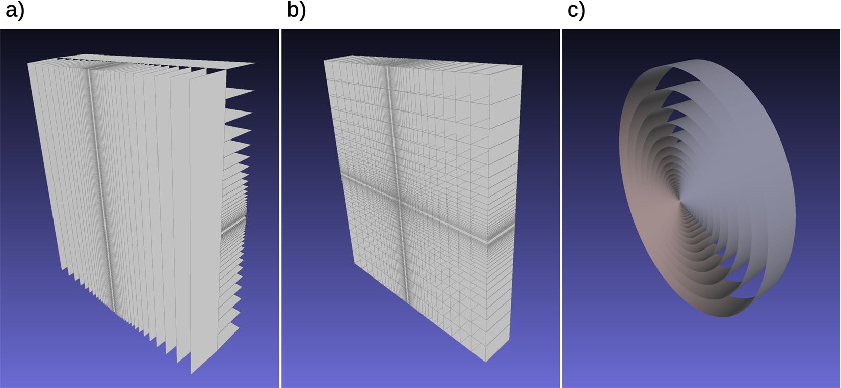
Figure 2 shows examples of two basic implementations of NMO, having either planar (Figs 2a and 2b) or toroidal (Fig. 2c) symmetry. In the latter case, the device is rotationally symmetric about the optical axis, with each mirror surface being a section of an ellipsoid of revolution. In this implementation, a neutron at M is transported to M’ by a single reflection. For NMO with planar symmetry, each mirror surface is a section of an ellipse having local translational symmetry transverse to both the optical axis and the mirror surface normal. In such a construction, two planar NMO with a relative orientation of 90 about the optical axis are required, as shown in Figs 2a and 2b. Such systems image the beam by two reflections, one for each transverse dimension. A first experimental demonstration of a single-planar elliptic NMO and a discussion of further applications of NMO for neutron delivery and beam focusing can be found in Ref. [16]. To be noted is also that the NMO discussed here are conceptually simpler than (and involve only half of the reflections occurring in) Wolter imaging systems. Initially developed for X-rays, they focus a parallel beam by double reflections off a combination of parabolic with hyperbolic or elliptical mirrors. Adapted to slow neutrons [29], a microscope based on three nested coaxial Wolter mirrors has already been demonstrated [24].

One major advantage of NMO over neutron guides is their ability to efficiently transport neutrons with larger angles to the beam axis, which, recalling that Ω(λ)m2, constitute a large portion of the beam. Furthermore, the NMO transports all neutrons with only one (toroidal) or two (double-planar) reflections, so that, for each range of angles from the optical axis that is covered by one mirror section of the NMO, the transport efficiency varies only linearly (toroidal) or quadratically (double-planar) with imperfect reflectivity, and not in higher powers as for large angles in a guide.

Fig. 2.

Examples of NMO types for neutron transport by “imaging”: a) two separated planar mirror assemblies; b) two intersecting planar assemblies (double-planar); c) toroidal assembly.

Examples of NMO types for neutron transport by “imaging”: a) two separated planar mirror assemblies; b) two intersecting planar assemblies (double-planar); c) toroidal assembly.

Another advantage of NMO over neutron guides is the ability of the former to tailor the beam spectrum to the desired application (see Ref. [52] for several illustrations). This is possible because reflections at a given surface occur only within a narrow band of angles for which they are kinematically possible, allowing each mirror to be optimized to reflect those neutrons by which it is illuminated. This opens up new possibilities for producing a short-wavelength cutoff to the transported beam spectrum. Setting this cutoff to a value slightly below 8.9A˚ would remove the main part of the spectrum from the beam incident on the converter and hence eliminate the heat load and background associated with neutrons that increases UCN production by only 30% at most (see the discussion of multi-phonon UCN production in Section 3). Note that achieving a common cutoff requires the m-values of the supermirrors to decrease with decreasing semi-minor axis, which is also economically interesting, as lower-m mirrors require fewer layers in the multi-layer structure.

Going a step further, one could even prepare monochromatic beams. Concerning UCN production, NMO equipped with bandpass supermirrors [7,25,38] that have high reflectivity for only a narrow range of neutron wavelengths centered on 8.9A˚ are of particular interest. First, in addition to the common short-wavelength cutoff discussed before, such mirrors would also remove most of the longer wavelengths. Second, bandpass supermirrors have higher reflectivity at the target wave-vector transfer than broadband supermirrors, corresponding to better transport efficiency for 8.9A˚ neutrons. Moreover, they consist of far fewer bilayers, making them cheaper and easier to manufacture. The use of an NMO equipped with such supermirrors would be significantly more efficient than, for example, a velocity selector at the end of a guide to “clean” the spectrum incident on the converter [31].

The advantages of NMO do not end there however. Using NMO with polarizing broadband supermirrors, which would not introduce additional efficiency losses as might a dedicated polarization device, would enable polarization of the cold neutron beam incident on the converter. As has been experimentally demonstrated [46], due to the absence of nuclear spin or atomic magnetic fields in 4He, He-II-based UCN production proceeds without “spin-flipping”, allowing cold neutrons to maintain their polarization as they are converted to UCN. Thus, a beam of polarized cold neutrons produces an ensemble of polarized UCN, necessary for experiments like the multi-cell approach to the neutron EDM search described in Ref. [5]. Additionally, for those experiments that permit it, wall losses may be significantly reduced by surrounding the storage container with a multipole magnet [55].

Assuming no drastic decrease in the mean flux spectrum at the converter results from increasing the area of the beam Abeam at the converter entrance, such a modification has several benefits for UCN production. First, a larger Abeam results in a larger total rate of neutrons incident on the converter, and thus a larger total UCN production rate. Since the mean free path of UCN in the converter vessel scales with Abeam, a larger beam also reduces the rate constant of UCN wall collisions, which, according to Eq. (8) with Eq. (9), increases the saturated UCN density. A larger Abeam also facilitates implementation of a multipole magnet around the converter, as there is more space for either the placement of a larger number of poles, which increases the phase space of storable “low-field seeking” polarized UCN, or the placement of stronger poles at lower multipole order. For an elongated source, a larger Abeam also reduces the number of reflections during beam transport through the converter, and hence reduces beam attenuation due to imperfect reflectivity at the converter walls. Furthermore, a larger Abeam increases the source volume, and reduces the severity of dilution losses for UCN extraction to an external volume.

Fig. 3.

Partially integrated brilliance transfer B, defined in Ref. [16], for a single-planar elliptic NMO scaled in proportion to the separation 2f, where f is the focal length (see the text). Solid and dashed curves correspond to simulations with and without gravity, respectively.

Partially integrated brilliance transfer B, defined in Ref. [16], for a single-planar elliptic NMO scaled in proportion to the separation 2f, where f is the focal length (see the text). Solid and dashed curves correspond to simulations with and without gravity, respectively.

The size of the beam extracted from the emission surface of the moderator, which is at most as large as the physical area of the moderator surface, influences the transport efficiency of an NMO and determines its optimal dimensions. To illustrate this, we show in Fig. 3 the results of Monte-Carlo simulations performed for a single-planar elliptic NMO with its mirrors oriented to reflect neutrons in the vertical plane. There, the “partially integrated brilliance transfer” B (see Ref. [16] for a precise definition) is plotted on the vertical axis as a function of focal length. B gives a quantitative measure of the device’s ability to image neutrons from a horizontal slit of height h centered on the focal line M (not a focal point as in the 2-D picture of Fig. 1) onto a slit of the same height h at the focal line M’, and separated from M by twice the focal length, 2f. For example, B=1 would corresponds to 100% neutron transport from slit to slit. The three pairs of curves in Fig. 3 correspond to simulations performed for three different values of h, in which the dimension of the NMO in the direction transverse to the optical axis is scaled in proportion to the focal length f, i.e., constant eccentricity.

The solid curves in Fig. 3 all follow the same general trend: for a given slit height h, the efficiency B monotonically increases with increasing f up to a maximum, whereafter it monotonically decreases. This maximum occurs at increasing f for increasing h. Much of this behavior can be explained by several considerations. First, for purely geometrical reasons, some neutrons starting with an offset from the focal line either pass the NMO unreflected or undergo two reflections, and hence do not arrive within the target slit. The proportion of such neutrons scales roughly with h/bn, where bn is the semi-minor axis, i.e., in the direction transverse to the optical axis, of the nth ellipse. Thus, the effect is initially greatest for the largest slit (green curve), and decreases as the size of the NMO increases, i.e., with increasing f. Another effect favoring large NMO is the decreased importance of the “divergence hole” for small angles; see Ref. [16] for an explanation. Second, large losses are present for large separations because, there, neutron trajectories are significantly curved by gravity. “Switching off” gravity, see the dashed curves in Fig. 3, results in a restoration of linear neutron trajectories, and hence in increased efficiency with increasing NMO size.

From these simulations, based on NMO using m=6 broadband supermirrors with 67% edge reflectivity, it is apparent that transport of a beam with extent as great as 20cm to a position farther than 30m from the moderator surface is possible with efficiency in excess of 75%. Such a separation places the NMO completely outside the largely-inaccessible region within the shielding bunker at the ESS, and still-larger distances would increase the efficiency to its maximum at 2f100m. However, such additional gains come at the price of an increased technical complexity and monetary cost associated with constructing a proportionally larger NMO.

5.In-beam UCN source implementation at the ESS

Having discussed in the previous two sections many of the concepts that are key to optimizing in-beam UCN production, we shall now apply them in order to estimate the UCN densities that may be possible at the ESS using NMO to transport cold neutrons to a He-II converter vessel. As discussed previously, the ideal location for such a UCN source would make use of the LBP, through which moderators in the vicinity of the spallation target wheel can be viewed with large solid angle (see “option 5” in Ref. [50]). During initial operation of the ESS spallation source, only the compact “bi-spectral” moderator system above the target wheel will be implemented [49]. This system includes the flat para-hydrogen moderator, which has an emission surface area and an expected surface averaged brilliance at λ=8.9A˚ of

(16)AparaH2=8x×3ycm2,andbparaH2=5.2×10¹¹s1cm2sr1A˚1at 5MW,
respectively. However, a large space below the spallation target is still available, in which the larger LD2 moderator, studied within the HighNESS project, can be placed [50]. In comparison to the para-hydrogen moderator, its emission parameters are
(17)ALD2=40x×24ycm2,andbLD2=3.4×10¹¹s1cm2sr1A˚1at 5MW.

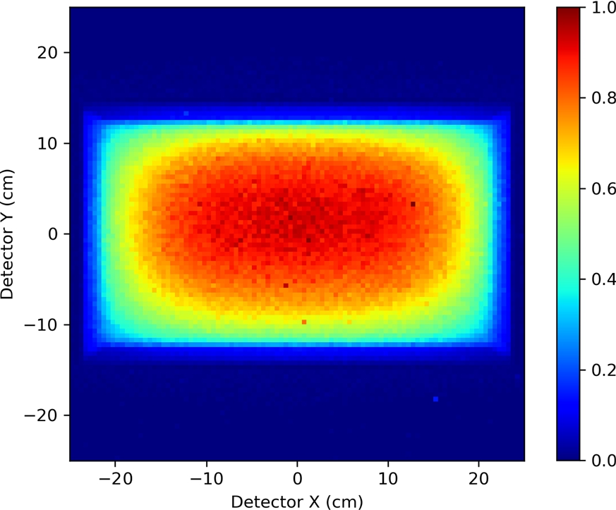
Figure 4 shows a simulated intensity map of neutrons with wavelengths near 8.9A˚ emitted by the surface of this larger moderator. Although its mean brightness is smaller by a factor of 1.5 in comparison to the para-hydrogen moderator, its surface area is larger by a factor of 40. Thus, efficient transport to the converter surface of cold neutrons leaving the LD2 moderator would result in a much larger total UCN production rate in comparison to the para-hydrogen moderator. For this reason, the LD2 moderator would be preferred for the subsequent operational stages at the ESS. While the small size of the para-hydrogen moderator does not preclude its use for an in-beam UCN source, it would restrict the total UCN production rate, and thereby the possible scope of such a source.

Fig. 4.

Simulated intensity map at the ESS LD2 moderator surface of neutrons with wavelengths near 8.9A˚. The data shown, which are normalized to the maximum, correspond to neutrons detected at 4m from the emission surface after having passed through a “pinhole” halfway between the detector and moderator. Note that an image produced by such a “camera obscura” is inverted, and that the map shown has been mirrored up-down and left-right to represent the moderator surface as it would be seen looking through the LBP. The maximum intensity occurs closer to the upper end, above which the target wheel is situated.

Simulated intensity map at the ESS LD2 moderator surface of neutrons with wavelengths near 8.9A˚. The data shown, which are normalized to the maximum, correspond to neutrons detected at 4m from the emission surface after having passed through a “pinhole” halfway between the detector and moderator. Note that an image produced by such a “camera obscura” is inverted, and that the map shown has been mirrored up-down and left-right to represent the moderator surface as it would be seen looking through the LBP. The maximum intensity occurs closer to the upper end, above which the target wheel is situated.

Extraction of the divergent beam at 8.9A˚ from the LD2 moderator by an elliptic NMO, discussed in Section 4, requires a large solid angle. Although this is possible through the LBP, the rather “anisotropic” access geometry there makes this task less than straightforward. We note, however, that no horizontally reflecting mirrors close to the moderator are necessary, keeping the view of the moderator surface at neighboring beamlines unobstructed and thus available for other purposes. Let us first consider the horizontal direction. The maximal angle θx at which an NMO can view a surface element within a central region of the moderator depends on the width wmod of this region. Taking wmod=22cm, for example, a choice that is motivated further below, would correspond to θx=5.6, and would require an m=6.4 coating on the outermost NMO mirrors.

In the vertical direction, access is limited from the bottom by a
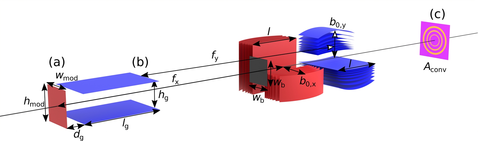
 2m long horizontal shielding plate, which, unlike that leading away from the top of the moderator, is flat rather than tapered; see Fig. 5 in Ref. [50]. Therefore, in order to minimize losses of neutrons emitted downward, the bottom plate should be covered by a mirror starting close to the moderator. If one then places a second mirror, parallel to this, one obtains a vertical, “one-dimensional” guide of height hg and length lg (see Fig. 5). A planar elliptic NMO with horizontal mirrors can then extract neutrons from the “virtual source” defined by the end of this guide. To minimize the fraction of neutrons transported by multiple reflections in the guide, hg should be maximized, which is also in line with the aim of maximizing the viewable portion of the moderator surface. Choosing hg=22cm, which is slightly less than the height of the moderator emission surface (24cm), would permit full vertical illumination of the guide when there is a gap dg of several centimeters, likely necessary for technical reasons, between its entrance and the moderator surface.

Fig. 5.

Schematic of the proposed Neutron Optical Delivery System for the Large Beam Port at the ESS. The values for the parameters quoted below are those used in the Monte-Carlo simulations shown in Fig. 6. The distance between the moderator, at left, and the converter entrance, at right, is 35m. Neutrons are emitted at the LD2 moderator surface from an area wmod×hmod, where the physical height hmod=24cm. Note that, as the horizontal edge of the viewed area on the moderator is not sharply defined, the simulations used wmod=24cm, slightly larger than stated in the text. Neutrons are initially guided in the vertical direction by two parallel, flat mirrors (lg=2.85m, hg=22cm) separated from the moderator by a gap of dg=10cm. The beam is imaged onto Aconv by two planar elliptic NMO that consist of mirrors of lengths l=0.5m. The semi-minor axis of the outermost mirror of both devices is b0,x=b0,y=1.85m. The vertically focussing NMO has a focal length of fy=16.025m and is placed halfway between Aconv and the end of the flat mirrors, whereas the horizontally focussing NMO (fx=17.5m) is centred between Aconv and the moderator. All mirrors of the NODS are coated with the same broadband m=6.4 supermirror, having 64% edge reflectivity. The mirrors of the NMO are deposited on 0.5mm thick silicon substrates, and the simulation accounts for neutron refraction and absorption by these substrates. A beam stop of area wb2=0.25m2 placed in front of the first NMO blocks the direct view of moderator at the converter. For the purpose of illustration, the eccentricity of the NMO and mirror curvatures have been exaggerated.

Schematic of the proposed Neutron Optical Delivery System for the Large Beam Port at the ESS. The values for the parameters quoted below are those used in the Monte-Carlo simulations shown in Fig. 6. The distance between the moderator, at left, and the converter entrance, at right, is 35m. Neutrons are emitted at the LD2 moderator surface from an area wmod×hmod, where the physical height hmod=24cm. Note that, as the horizontal edge of the viewed area on the moderator is not sharply defined, the simulations used wmod=24cm, slightly larger than stated in the text. Neutrons are initially guided in the vertical direction by two parallel, flat mirrors (lg=2.85m, hg=22cm) separated from the moderator by a gap of dg=10cm. The beam is imaged onto Aconv by two planar elliptic NMO that consist of mirrors of lengths l=0.5m. The semi-minor axis of the outermost mirror of both devices is b0,x=b0,y=1.85m. The vertically focussing NMO has a focal length of fy=16.025m and is placed halfway between Aconv and the end of the flat mirrors, whereas the horizontally focussing NMO (fx=17.5m) is centred between Aconv and the moderator. All mirrors of the NODS are coated with the same broadband m=6.4 supermirror, having 64% edge reflectivity. The mirrors of the NMO are deposited on 0.5mm thick silicon substrates, and the simulation accounts for neutron refraction and absorption by these substrates. A beam stop of area wb2=0.25m2 placed in front of the first NMO blocks the direct view of moderator at the converter. For the purpose of illustration, the eccentricity of the NMO and mirror curvatures have been exaggerated.

Although such a situation does not correspond to a true optimization of the complete NODS, let us consider the case in which lg is selected so that the vertical range of angles under which the NMO can view the guide exit is the same as the horizontal range of angles under which it can view the width wmod on the moderator; i.e., θy=θx=5.6. This will be satisfied when lg is slightly less than 3m. Supposing that this guide uses the same broadband m=6.4 supermirror as in the NMO, the majority of cold neutrons incident on the guide surfaces at the critical angle θc=5.6 would be transported by only a single reflection.

For this geometry, a double-planar elliptic NMO would be best adapted to image the beam, whose horizontal and vertical extents are defined at the moderator surface and guide end, respectively, onto the He-II converter. As shown in Fig. 5, two separate NMO with different focal lengths
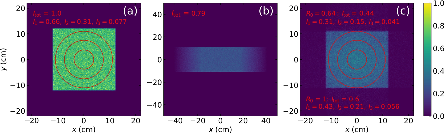
 fx and fy are required. He-II converter vessels are most often cylindrical in shape, which is advantageous for the implementation of a magnetic multipole reflector. This motivates the choice of the viewed width of the moderator surface to be wmod=hg=22cm. However, the linear extensions wmod and hg must then satisfy wmodhgdconv=2Aconv/π in order to avoid under-illumination of the circular converter surface. Extraction of a rectangular beam of nearly the full moderator size would also be possible by a double planar NMO. However, as the angular range of view onto the whole surface would be reduced by the biological shielding near the moderator, this option would profit from also guiding the neutrons inside the shielding in the horizontal direction.

Fig. 6.

Simulated intensity distributions at the locations as labelled in Fig. 5, for R0=64% supermirror edge reflectivity. I1, I2, and I3 are the fractional intensities encompassed by the red circles of diameters d1=22cm, d2=15cm, and d3=7.5cm, respectively, normalized to the total intensity Itot, which is taken as unity at the moderator surface. (a) Intensity of neutrons emitted from the area wmod×hmod at the moderator for uniform brilliance within angular and wavelength ranges of 5.6θx, θy5.6 and 8.7A˚λ9.1A˚, respectively. (b) Intensity at the end of the two flat horizontal mirrors. The total intensity Itot here, and also at (c), is normalized to the total intensity at (a). The sharp vertical boundaries are due to the mirrors, while the horizontal spread in intensity is due to beam expansion. (c) Intensity at the converter entrance. The red circles have the same diameters as in (a). Within the largest circle, the intensity ratio is I1(c)/I1(a)=47% (for R0=64%), while for the smallest circle it is slightly better: I3(c)/I3(a)=53%. If I1(c)/I1(a) is further reduced, conservatively, by 15% on account of imperfections of the NMO and absorption and scattering at beam windows, we can estimate the transport efficiency as in Eq. (6), with the flux spectra replaced by their area averages, to be ϵtr=40% for a converter entrance window of diameter dconv=22cm. The lower fractional intensities refer to a second simulation preformed for ideal reflectivity of both NMO, R0=100%.

Simulated intensity distributions at the locations as labelled in Fig. 5, for R0=64% supermirror edge reflectivity. I1, I2, and I3 are the fractional intensities encompassed by the red circles of diameters d1=22cm, d2=15cm, and d3=7.5cm, respectively, normalized to the total intensity Itot, which is taken as unity at the moderator surface. (a) Intensity of neutrons emitted from the area wmod×hmod at the moderator for uniform brilliance within angular and wavelength ranges of −5.6∘⩽θx, θy⩽5.6∘ and 8.7A˚⩽λ⩽9.1A˚, respectively. (b) Intensity at the end of the two flat horizontal mirrors. The total intensity Itot here, and also at (c), is normalized to the total intensity at (a). The sharp vertical boundaries are due to the mirrors, while the horizontal spread in intensity is due to beam expansion. (c) Intensity at the converter entrance. The red circles have the same diameters as in (a). Within the largest circle, the intensity ratio is I1(c)/I1(a)=47% (for R0=64%), while for the smallest circle it is slightly better: I3(c)/I3(a)=53%. If I1(c)/I1(a) is further reduced, conservatively, by 15% on account of imperfections of the NMO and absorption and scattering at beam windows, we can estimate the transport efficiency as in Eq. (6), with the flux spectra replaced by their area averages, to be ϵtr=40% for a converter entrance window of diameter dconv=22cm. The lower fractional intensities refer to a second simulation preformed for ideal reflectivity of both NMO, R0=100%.

The implementation of a vertical guide close to the ESS spallation target is complicated by the high flux of fast neutrons there. Even for supermirrors on metallic substrates, developed for in-pile guide sections, sufficient radiation hardness still needs to be experimentally demonstrated. If such a guide is not feasible, beam extraction would have to be accomplished solely by NMO, in which case, the aforementioned geometrical restrictions and partial obstruction of the moderator view would reduce the possible UCN yield.

Using the neutron transport efficiency of the NODS shown in Fig. 5, estimated from the simulations shown in Fig. 6 to be ϵtr=40%, we can finally give estimates for UCN production induced by the single-phonon process in a He-II converter installed at a distance of 35m from the LD2 moderator. The production rate density in a short converter with an entrance window of diameter dconv=22cm follows from using Eq. (5) with bmod=bLD2 from Eq. (17) and Ωmod=4×(5.6)2=0.038sr (Eq. (14) with γ=4), Eq. (6) with ϵtr=0.4 and Ωconv=Ωmod, and Eq. (10), resulting in

(18)pI=260s1cm3
for a trap depth of Vconv=233neV, and a time-averaged power of 5MW of the spallation source. Assuming the UCN storage time constant of the converter to be τ=300s, the corresponding saturated UCN density (Eq. (8)) will be
(19)ρsat=7.8×104cm3
in a short converter.

Maximal UCN production in the converter would be obtained by matching its entrance shape to that of the rectangular beam provided by the NODS, which is shown in Fig. 6 with a circular converter entrance. Placing an m=6.4 supermirror neutron guide at the converter walls would then transport the provided neutron beam through an elongated source, within which the volume-averaged UCN production density would be decreased by imperfect reflectivity and by transmission losses, Eq. (12). In a source with a cylindrical supermirror guide, the transported neutron flux would be reduced by a factor π/4, cf. Eq. (14). For such a situation, with a converter having diameter 22cm and length 3m, and assuming a loss of UCN production on the order of 20% due to imperfect mirror reflectivity, the total UCN production rate PI and total saturated UCN number Nsat in the converter would be

(20)PI=1.7×10⁷s1,andNsat=5.1×10⁹.

6.Conclusions and outlook

The parameters of the UCN in-beam type source described in this paper, quoted in Eqs (18)–(20), make it a very attractive option for the community of UCN users. As the only current in-beam type, general-purpose UCN source project beyond ILL’s SuperSUN [3], it offers a saturated UCN density at the top of the range of other current projects, which all rely on UCN production in the vicinity of a strong primary cold neutron source. The high density is the result of UCN accumulation in He-II kept at a temperature so low as to render neutron up-scattering negligible, which is possible at a position far away from the primary neutron source, where only less than 1W cooling power is needed. This kind of UCN source is thus complementary to in-pile type projects, which generally possess a much higher UCN production rate. Quoting here, only for comparison, what is perhaps the most ambitious of these projects proposed for LANSCE [22], the “inverse-geometry spallation-driven UCN source” is designed to cool away 100W from 40L He-II at 1.6K, resulting in a UCN production rate density of p=5×10⁴s1cm3 and a UCN flux of 5×10⁸s1 through a 5m long, 18cm diameter guide which would enable UCN densities up to 104cm3 in a large external trap.

Not to be underestimated in any source comparison are also the practical advantages of the converter being placed far away from strong radiation fields of the primary source. There, the required cooling power is much reduced, the UCN source is accessible to trouble-shooting, UCN need to be transported only over short distances, and, finally yet importantly, nuclear licensing procedures will not directly hamper the project. As a very valuable property for experimenters, in-beam sources based on NMO have great flexibility to adapt the implementation of the optics and the He-II converter to the physics project, including the in-situ strategies presented in Ref. [5].

Particularly appealing in this respect is the possibility to trade maximal total UCN production against highest possible UCN density. A class of experiments that could take advantage of this possibility is the search for dark matter and dark energy via investigation of the gravitational quantum states of the neutron above a horizontal mirror. Current experiments by the qBounce collaboration [18] are performed using a beam of UCN and have already led to constraints on new physics [4,19]. A route towards further increase of sensitivity in such investigations consists in UCN trapping to prolong the time of controlled exposure of the quantum states to the field [30]. To this end, a high-density source from which one would extract only UCN in the desired quantum state [37] would be of great interest.

Focusing of the cold neutron beam incident on the He-II converter would enable a large gain in flux density and hence UCN production rate density, for which the NMO based magnifying-optics concepts presented in Ref. [16] should be further investigated. As the focused beam illuminates the converter under a solid angle Ωconv>Ωmod that may exceed by far the solid angle transportable by a guide equipped with even the most advanced supermirror coating, the converter has to be reasonably short to avoid dilution due to beam expansion behind the focal point of the optics. The correspondingly reduced beam size reduces the size of the converter and hence the mean free path of the UCN between wall collisions (which scales as Aconv). Highly reflective walls and/or magnetic trapping may keep losses due to the accordingly increased rate of UCN wall collisions well under control. Very helpful in this respect is the large emission surface of the LD2 moderator foreseen at the ESS. Besides the aforementioned UCN trapping in quantum states, beam focusing by NMO could result in large additional gains with respect to the performance numbers given in Eqs (18) and (19), which might also open the door to other qualitatively new experiments.

Acknowledgements

This work was supported by the HighNESS project funded by the European Framework for Research and Innovation Horizon 2020, under grant agreement 951782.

References

[1] 

M.W. Ahmed, R. Alarcon, A. Aleksandrova et al., A new cryogenic apparatus to search for the neutron electric dipole moment, Journal of Instrumentation 14: (11) ((2019) ), 11017. doi:10.1088/1748-0221/14/11/p11017.

[2] 

C.A. Baker, S.N. Balashov, J. Butterworth et al., Experimental measurement of ultracold neutron production in superfluid 4He, Phys. Lett. A 308: ((2003) ), 67–74. doi:10.1016/S0375-9601(02)01773-5.

[3] 

E. Chanel et al., Concept and strategy of SuperSUN: A new ultracold neutron converter, these proceedings.

[4] 

G. Cronenberg, P. Brax, H. Filter, P. Geltenbort, T. Jenke, G. Pignol, M. Pitschmann, M. Thalhammer and H. Abele, Acoustic Rabi oscillations between gravitational quantum states and impact on symmetron dark energy, Nat. Phys. 14: ((2018) ), 1022. doi:10.1038/s41567-018-0205-x.

[5] 

S. Degenkolb, P. Fierlinger and O. Zimmer, Approaches to in-situ production and detection of ultracold neutrons for high-density storage experiments, these proceedings.

[6] 

D. Dubbers and M.G. Schmidt, The neutron and its role in cosmology and particle physics, Rev. Mod. Phys. 83: ((2011) ), 1111. doi:10.1103/RevModPhys.83.1111.

[7] 

T. Ebisawa, N. Achiwa, S. Yamada, T. Akiyoshi and S. Okamoto, Neutron reflectivities of Ni–Mn and Ni–Ti multilayers for monochromators and supermirrors, J. Nucl. Sci. Technol. 16: ((1979) ), 647–659. doi:10.1080/18811248.1979.9730960.

[8] 

R. Golub, On the storage of neutrons in superfluid 4He, Physics Letters A 72: (4–5) ((1979) ), 387–390. doi:10.1016/0375-9601(79)90505-X.

[9] 

R. Golub and K. Böning, New type of low temperature source of ultra-cold neutrons and production of continuous beams of UCN, Z. Phys. B 51: ((1983) ), 95–98. doi:10.1007/BF01308763.

[10] 

R. Golub, C. Jewell, P. Ageron, W. Mampe and B. Heckel, Operation of a superthermal ultra-cold neutron source and the storage of ultra-cold neutrons in superfluid Helium-4, Z. Phys. B 51: ((1983) ), 187–193. doi:10.1007/BF01307673.

[11] 

R. Golub and J. Pendlebury, Super-thermal sources of ultra-cold neutrons, Phys. Lett. A 53: ((1975) ), 133–135. doi:10.1016/0375-9601(75)90500-9.

[12] 

R. Golub and J. Pendlebury, The interaction of ultra-cold neutrons (UCN) with liquid helium and a superthermal UCN source, Phys. Lett. A 82: ((1977) ), 337–339. doi:10.1016/0375-9601(77)90434-0.

[13] 

R. Golub, D.J. Richardson and S.K. Lamoreaux, Ultra-Cold Neutrons, Adam Hilger, Bristol, (1991) .

[14] 

E. Gutsmiedl, F. Böhle, A. Frei, A. Maier, S. Paul, A. Orecchini and H. Schober, Production of ultra-cold neutrons in solid α-oxygen, Europ. Phys. Lett. 96: ((2011) ), 62001. doi:10.1209/0295-5075/96/62001.

[15] 

J.B. Hayter and H.A. Mook, Discrete thin-film multilayer design for X-ray and neutron supermirrors, J. Appl. Cryst. 22: ((1989) ), 35–41. doi:10.1107/S0021889888010003.

[16] 

C. Herb, O. Zimmer, R. Georgii and P. Böni, Nested mirror optics for neutron extraction, transport, and focusing, Nuclear Instrument and Methods in Physics Research A 1040: ((2022) ), 167154. doi:10.1016/j.nima.2022.167154.

[17] 

P.R. Huffman, C.R. Brome, J.S. Butterworth et al., Magnetic trapping of neutrons, Nature 403: ((2000) ), 62–64. doi:10.1038/47444.

[18] 

T. Jenke, J. Bosina, G. Cronenberg et al., Testing gravity at short distances: Gravity resonance spectroscopy with q bounce, EPJ Web of Conferences 219: ((2019) ), 05003. doi:10.1051/epjconf/201921905003.

[19] 

T. Jenke, G. Cronenberg, J. Burgdörfer et al., Gravity resonance spectroscopy constrains dark energy and dark matter scenarios, Phys. Rev. Lett. 112: ((2014) ), 151105. doi:10.1103/PhysRevLett.112.151105.

[20] 

S. Kawasaki and T. Okamura (TUCAN collaboration), Cryogenic design for a high intensity ultracold neutron source at TRIUMF, EPJ Web of Conferences 219: ((2019) ), 10001. doi:10.1051/epjconf/201921910001.

[21] 

E. Korobkina, R. Golub, B.W. Wehring and A.R. Young, Production of UCN by downscattering in superfluid He4, Physics Letters A 301: (5–6) ((2002) ), 462–469. doi:10.1016/S0375-9601(02)01052-6.

[22] 

K.K.H. Leung, G. Muhrer, T. Hügle, T.M. Ito, E.M. Lutz, M. Makela, C.L. Morris, R.W. Pattie Jr., A. Saunders and A.R. Young, A next-generation inverse-geometry spallation-driven ultracold neutron source, Journal of Applied Physics 126: ((2019) ), 224901, (2019) arXiv:1905.09459. doi:10.1063/1.5109879.

[23] 

C.-Y. Liu and A.R. Young, Ultra-cold neutron production in anti-ferromagnetic oxygen solid, 2004, arXiv:nucl-th/0406004.

[24] 

D. Liu, D. Hussey, M.V. Gubarev, B.D. Ramsey et al., Demonstration of achromatic cold-neutron microscope utilizing axisymmetric focusing mirrors, Appl. Phys. Lett. 102: ((2013) ), 183508. doi:10.1063/1.4804178.

[25] 

S. Masalovich, Analysis and design of multilayer structures for neutron monochromators and supermirrors, Nucl. Instrum. Methods Phys. Res. A 722: ((2013) ), 71. doi:10.1016/j.nima.2013.04.051.

[26] 

Y. Masuda, K. Hatanaka, S.-C. Jeong et al., Spallation ultracold neutron source of superfluid helium below 1 K, Phys. Rev. Lett. 108: ((2012) ), 134801. doi:10.1103/PhysRevLett.108.134801.

[27] 

P.V.E. McClintock, An apparatus for preparing isotopically pure He4, Cryogenics 18: ((1978) ), 201–208. doi:10.1016/0011-2275(78)90002-4.

[28] 

F. Mezei, Novel polarized neutron devices: Supermirror and spin component amplifier, Commun. Phys. 1: ((1976) ), 81–85.

[29] 

D.F.R. Mildner and M.V. Gubarev, Wolter optics for neutron focusing, Nucl. Instrum. Methods Phys. Res. A 634: ((2011) ), S7. doi:10.1016/j.nima.2010.06.093.

[30] 

V.V. Nesvizhevsky, F. Nez, S.A. Vasiliev, E. Widmann, P. Crivelli, S. Reynaud and A.Y. Voronin, A magneto-gravitational trap for studies of gravitational quantum states, Eur. Phys. J. C 80: ((2020) ), 520. doi:10.1140/epjc/s10052-020-8088-2.

[31] 

J.M. Pendlebury and G.L. Greene, Considerations for an intense source of ultracold neutrons at the European long pulse Spallation Source, Phys. Procedia 51: ((2014) ), 78–84. doi:10.1016/j.phpro.2013.12.018.

[32] 

F.M. Piegsa, M. Fertl, S.N. Ivanov, M. Kreuz, K.H. Leung, P. Schmidt-Wellenburg, T. Soldner and O. Zimmer, New source for ultracold neutrons at the Institut Laue Langevin, Phys. Rev. C 90: ((2014) ), 015501. doi:10.1103/PhysRevC.90.015501.

[33] 

D.J. Salvat, E. Gutsmiedl, C.-Y. Liu, P. Geltenbort, A. Orecchini, S. Paul and H. Schober, Investigating solid α-15N2 as a new source of ultra-cold neutrons, Europ. Phys. Lett. 103: ((2013) ), 12001. doi:10.1209/0295-5075/103/12001.

[34] 

V. Santoro, K.H. Andersen, D.D. DiJulio, E.B. Klinkby, T.M. Miller, D. Milstead, G. Muhrer, M. Strobl, A. Takibayev, L. Zanini and O. Zimmer, Development of high intensity neutron source at the European Spallation Source, Journal of Neutron Research 22: (2–3) ((2020) ), 209. doi:10.3233/JNR-200159.

[35] 

P. Schmidt-Wellenburg et al., Experimental study of ultracold neutron production in pressurized superfluid helium, Phys. Rev. C 92: ((2015) ), 024004. doi:10.1103/PhysRevC.92.024004.

[36] 

P. Schmidt-Wellenburg, K.H. Andersen and O. Zimmer, Ultra-cold neutron production by multiphonon processes in superfluid helium under pressure, Nucl. Instr. Meth. A 611: ((2009) ), 259. doi:10.1016/j.nima.2009.07.085.

[37] 

P. Schmidt-Wellenburg, J. Barnard, P. Geltenbort, V.V. Nesvizhevsky, C. Plonka, T. Soldner and O. Zimmer, Reflection and collimation of ultra-cold neutrons employing a semidiffuse channel, Nucl. Instr. Meth. A 577: ((2007) ), 623. doi:10.1016/j.nima.2007.03.032.

[38] 

M. Schneider, J. Stahn and P. Böni, Focusing of cold neutrons: Performance of a laterally graded and parabolically bent multilayer, Nucl. Instrum. Meth. A 610: ((2009) ), 530–533. doi:10.1016/j.nima.2009.08.047.

[39] 

A. Serebrov, V. Liamkin, A. Fomin, V. Pusenkov, K. Keshishev, S. Boldarev, D. Prudnikov, A. Oprev, O. Samodurov, A. Koptyuhov and V. Ilatovsky, Development of a powerful UCN source at PNPI’s WWR-M reactor, EPJ Web of Conferences 219: ((2019) ), 10002. doi:10.1051/epjconf/201921910002.

[40] 

A.P. Serebrov, V.A. Mityuklyaev, A.A. Zakharov et al., Preparation of facilities for fundamental research with ultracold neutrons at PNPI, Nucl. Instr. Meth. A 611: ((2009) ), 276–279. doi:10.1016/j.nima.2009.07.078.

[41] 

Y.C. Shin, W.M. Snow, D.V. Baxter, C.-Y. Liu, D. Kim, Y. Kim and Y.K. Semertzidis, Ultracold neutron production at compact neutron sources, 2018, arXiv:1810.08722v3.

[42] 

H.S. Sommers Jr., J.G. Dash and L. Goldstein, Transmission of slow neutrons by liquid helium, Phys. Rev. 97: ((1955) ), 855. doi:10.1103/PhysRev.97.855.

[43] 

A. Steyerl, H. Nagel, F.X. Schreiber, K.A. Steinhauser, R. Gaehler, W. Glaeser, P. Ageron, J. Astruc, W. Drexel, G. Gervais et al., A new source of cold and ultracold neutrons, Phys. Lett. A 116: ((1986) ), 347. doi:10.1016/0375-9601(86)90587-6.

[44] 

SwissNeutronics, https://www.swissneutronics.ch/products/neutron-supermirrors/.

[45] 

M. Utsuro and V.K. Ignatovich, Handbook of Neutron Optics, Wiley-VCH, Weinheim, (2010) . ISBN 978-3-527-40885-6.

[46] 

M.G.D. van der Grinten, CryoEDM: A cryogenic experiment to measure the neutron electric dipole moment, Nucl. Instr. Meth. A 611: ((2009) ), 129–132. doi:10.1016/j.nima.2009.07.040.

[47] 

H. Yoshiki, The cross sections for one phonon emission and absorption by slow neutrons in superfluid Helium, Computer Phys. Communications 151: ((2003) ), 141–148. doi:10.1016/S0010-4655(02)00819-6.

[48] 

H. Yoshiki, H. Nakai and E. Gutsmiedl, A new superleak to remove He3 for UCN experiments, Cryogenics 45: ((2005) ), 399–403. doi:10.1016/j.cryogenics.2005.01.007.

[49] 

L. Zanini, K.H. Andersen, K. Batkov, E.B. Klinkby, F. Mezei, T. Schönfeldt and A. Takibayev, Design of the cold and thermal neutron moderators for the European Spallation Source, Nucl. Instrum. Meth. A 925: ((2019) ), 33. doi:10.1016/j.nima.2019.01.003.

[50] 

L. Zanini, E. Dian, D.D. Diulio et al., Very cold and ultra cold neutron sources for ESS, these proceedings.

[51] 

O. Zimmer, Neutron conversion and cascaded cooling in paramagnetic systems for a high-flux source of very cold neutrons, Phys. Rev. C 93: ((2016) ), 035503. doi:10.1103/PhysRevC.93.035503.

[52] 

O. Zimmer, Imaging nested-mirror assemblies – a new generation of neutron delivery systems?, J. Neutron Res. 20: ((2018) ), 91–98. doi:10.3233/JNR-190101.

[53] 

O. Zimmer, Multi-mirror imaging optics for low-loss transport of divergent neutron beams and tailored wavelength spectra, 2016, arXiv:1611.07353v1.

[54] 

O. Zimmer, K. Baumann, M. Fertl, B. Franke, S. Mironov, C. Plonka, D. Rich, P. Schmidt-Wellenburg, H.-F. Wirth and B. van den Brandt, Superfluid helium converter for accumulation and extraction of ultracold neutrons, Phys. Rev. Lett. 99: ((2007) ), 104801. doi:10.1103/PhysRevLett.99.104801.

[55] 

O. Zimmer and R. Golub, Ultracold neutron accumulation in a superfluid-helium converter with magnetic multipole reflector, Phys. Rev. C 92: ((2015) ), 015501. doi:10.1103/PhysRevC.92.015501.

[56] 

O. Zimmer, P. Schmidt-Wellenburg, M. Assmann, M. Fertl, J. Klenke, H.-F. Wirth and B. van den Brandt, Ultracold neutrons extracted from a superfluid-helium converter coated with fluorinated grease, Eur. Phys. J. C 67: ((2010) ), 589. doi:10.1140/epjc/s10052-010-1327-1.