
Development of UCN sources at PNPI
Abstract
This article reviews the development of various sources for ultracold neutrons (UCNs) at the Petersburg Nuclear Physics Institute (PNPI). For 45 years, PNPI has proposed and manufactured cryogenic devices for neutron conversion to low energies. Based on beryllium, hydrogen and deuterium, they can be operated in the intense radiation fields near the core of a nuclear reactor. A more recently launched UCN source development utilizes superfluid helium (He-II) as conversion medium. Initially proposed and designed for PNPI’s old WWR-M reactor, the project has been reshaped to equip the institute’s PIK reactor with a modern UCN source of this type. The projected UCN density in the closed source chamber is 2.2 × 103 cm−3, which, as calculations of neutron transport show, will provide 200 cm−3 in the chambers of a neutron EDM spectrometer connected to the source by a UCN guide. Experiments at PNPI with a full-scale UCN source model have demonstrated that a heat load of 60 W can be removed from the He-II in the converter at a temperature of 1.37 K. This fact confirms the practical possibility to implement low-temperature converters under “in-pile” conditions with large heat inflows. The review concludes with a presentation of various proposed options for a He-II based UCN source at the European Spallation Source.
1.Introduction
In investigations of fundamental properties of the neutron, it is often beneficial to use the slowest possible neutrons. These neutrons stay longer inside an experimental apparatus, which may increase the sensitivity of measurements if they can be made available with sufficient abundance. In the extreme case, neutrons have kinetic energy less than the neutron optical potential of a wall material. They can then be reflected under any angle of incidence and are called ultracold neutrons (UCNs). They can be stored in a volume closed by material walls [17] or by gradient fields of magnets with a multipole structure, due to interaction with the neutron magnetic moment [50]. Nowadays, UCNs are mainly used for fundamental research in particle physics. This notably includes searches for a nonzero electric dipole moment (EDM) of the neutron [1], measurements of the neutron lifetime [48], studies of decay asymmetries in neutron β-decay [49], and searches for dark matter and dark energy using gravity states of the neutron [20].
Efficient production of low-energy neutrons necessarily requires the use of cryogenic devices. Large yields of cold neutrons (CNs), very cold neutrons (VCNs) and UCNs can be obtained by exposing thermal reactor neutrons to a cold moderator, typically made of hydrogen or deuterium. The UCN density depends on the initial intensity of the reactor’s neutron flux and the efficiency of the cryogenic moderator (or converter, if single inelastic scattering events dominate). Unfortunately, the higher the neutron flux, the higher is the heat due to various radiations, which limits the achievable moderator temperature.
First experiments on UCN extraction from a reactor at the Joint Institute for Nuclear Research (JINR) at Dubna, Russia were carried out by the group of Shapiro in 1968 [24]. The scientific aim was to use UCNs to search for a non-vanishing EDM of the neutron. At about the same time, experiments by Steyerl investigated the transmission of slow neutrons down to 5 m/s to study low-energy neutron scattering at the Technical University Munich near Garching, Germany [45].
During the 1970–1980s, large efforts were made to develop experimental methods for the use of UCNs. Many institutions in Russia and beyond were involved in this process. Over the course of time, experimental UCN densities were increased by eight orders of magnitude compared to the first experiment at Dubna and reached a plateau at 10–40 cm−3. In the historical evolution of UCN source developments, shown in Fig. 1, the Petersburg Nuclear Physics Institute (PNPI) has been playing an important role. Highly efficient cryogenic methods were applied for UCN sources at PNPI’s old WWR-M research reactor, with parameters listed in Table 1. Most of these sources were «the world’s first» and the design of some of them were protected by copyright patents.
Fig. 1.
Evolution of UCN densities achieved over time in various UCN source developments (● PNPI; ▲ other; red – He-II based; green – solid-deuterium (sD2) based). Each symbol represents the year of (for projects: proposed) start of operation and the finally achieved (for projects: proposed) UCN density. Note that some values quote densities achieved in the source, some in external traps [3–5,7,11,13,19,21,30,33,43,46,56].
![Evolution of UCN densities achieved over time in various UCN source developments (● PNPI; ▲ other; red – He-II based; green – solid-deuterium (sD2) based). Each symbol represents the year of (for projects: proposed) start of operation and the finally achieved (for projects: proposed) UCN density. Note that some values quote densities achieved in the source, some in external traps [3–5,7,11,13,19,21,30,33,43,46,56].](https://content.iospress.com:443/media/jnr/2022/24-2/jnr-24-2-jnr220007/jnr-24-jnr220007-g001.jpg)
Table 1
Parameters of UCN sources developed at PNPI. The various source types (CBS: cold beryllium source, SLHS: small liquid hydrogen source, UCNS: universal cold neutron source, SDS: solid deuterium source) are described in separate sections further below, where also the meaning of the UCN gain factor is explained. LH2: liquid hydrogen, LD2: liquid deuterium, sD2: solid deuterium. In cells without entry, no information was available. *See text for definition of the gain factors
| Parameter | Type of UCN source | |||
| CBS | SLHS | UCNS | SDS | |
| Converter | Be | LH2 | 40% LH2 + 60% LD2 | sD2 |
| Thermal neutron flux (cm−2s−1) | 1014 | 6 × 10¹³ | (1.5–2) × 1014 | 1.7 × 10¹² |
| Fast neutron flux (cm−2s−1) | 8 × 10¹² | 2 × 10¹³ | 3 × 10⁹ | |
| UCN production rate (s−1) | 2 × 10⁴ | 4 × 10⁴ | (3–5) × 105 | |
| Cold neutron flux (cm−2s−1) | 1.8 × 10⁹ | |||
| UCN flux (cm−2s−1) | 5 × 10² | 103 | 6 × 10³ | |
| UCN gain factor* | 12 | 25 | 55 | 1230 |
Currently, nine Institutes in the world develop new and/or upgrade existing UCN sources (see Table 2). They are all based on only two technologies, using solid deuterium (sD2) or superfluid helium (He-II), with the goal to improve UCN densities and fluxes.
Table 2
Facilities (worldwide) that operate or project UCN sources
| Institute/facility | Progress over past years | Status in 2022 |
| PNPI | He-II UCN source design finished; UCN guide system for PIK reactor developed; full-scale source model started; 60 W heat load removed from He-II at 1.37 K | UCN source based on He-II under construction Isopure 4He being produced Expected UCN density in the source: 2.2 × 103 cm−3 Expected UCN density in nEDM experiment: 200 cm−3 |
| ILL | PF2 turbine user source (since 1985) [46]; He-II UCN source prototypes SUN-1 and SUN-2 developed and being used [29,31,56]; He-II source SuperSUN phase-I being commissioned [9] | PF2: up to 20 cm−3 in external UCN traps SUN-2: demonstrated 220 cm−3 in situ in 4 L SuperSUN phase-I: projected 330 cm−3 in situ in 14 L SuperSUN phase-II: projected 1670 cm−3 polarized in situ in 14 L [51] |
| TRIUMF | Spallation source based He-II UCN source demonstrated at RCNP [56] UCN source prototype installed and first UCNs produced at TRIUMF | He-II UCN source under construction Demonstrated UCN density in production and guide volume (60.8 L) of the prototype: 5.3 cm−3 Projected in-situ UCN density: 330 cm−3 in two nEDM cells of 30 L each [25] |
| PSI | Helium cooling system stability, control and sD2 structure improved; ortho-D2 content increased to 99.5% [22] | sD2 source operating; UCN density measured at 400 mm height with respect to beamport West-1 in a 20-L stainless steel bottle: about 13 cm−3 [22] |
| TRIGA-Mainz | sD2 source being used for experiments | sD2 source operating; UCN density outside the biological shield at the experimental area in 32-L stainless steel bottle: 8.5 cm−3 [21] |
| LANL | Optimization of cryostat and geometry of the replaceable moderator, new design of flapper source valve and modified UCN tee | sD2 source operating Density of polarized UCNs in nEDM trap: 39 cm−3 [19] |
| FRM II | Security Concept of UCNS approved He-cooling machine in operation Nuclear licensing procedure and installation of auxiliary systems ongoing | Under construction Calculated UCN density in the storage volumes of Mini-D2 right after the converter: up to 7 × 104 cm−3 [47] |
| LANSCE | Proposed He-II UCN source with large UCN production rate; optimization has been done | Expected UCN density: 104 cm−3 in <1000 L external experimental volumes [23] |
| SNS | In-situ He-II UCN source for nEDM experiment; extensive prototyping program on cryogenic magnet, light tube, polarimetry etc. | The collaboration aims to measure the nEDM with a sensitivity of ≃ 1028 e |
2.Ultracold-neutron sources developed and manufactured at PNPI
2.1.Cold beryllium source (CBS)
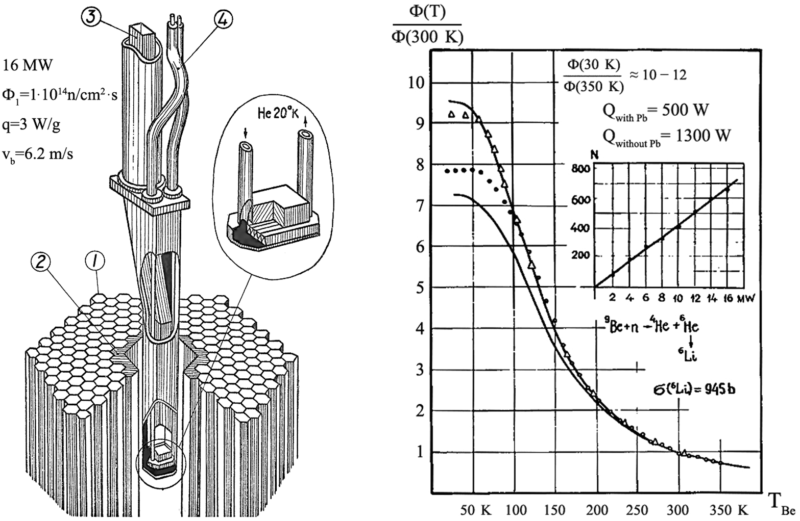
The history of UCN source developments at PNPI started in the early 1970s with a beryllium converter at ambient temperature, located in the center of the WWR-M reactor. While that first device was still rather ineffective for down-conversion of thermal neutrons to UCNs, the UCN yields were significantly improved after implementation of cryogenic infrastructure to cool the block of beryllium down to 30 K (see Fig. 2). A helium refrigerator of the type HGU-500/15 (HGU abbreviating «Holodilnaya Gelivaya Ustanovka» that translates as «Cold Helium Plant») was used for this purpose. To increase the thermal neutron flux in the converter, it was installed in a water cavity. The assembly was surrounded by a lead shield, which reduced the heat generated in the converter from 3 W/g to 1 W/g, so that less than 450–500 W had to be removed from the converter by the cold helium. A modernization of the refrigerator made it later possible to remove about 1300 W from the beryllium so that it could be operated without a lead shield, which made it possible to increase the thermal neutron flux in the beryllium converter by about a factor 2 and achieve a more stable mode of operation. Cooling the converter from 350 K down to its base temperature of 30 K increased the UCN flux by a factor up to 12 (see Fig. 2, right). This is what we call «UCN gain factor». The UCN flux at the entrance of the EDM spectrometer installed at this second version of source was 1.2 × 10⁴ s−1 [3].
Fig. 2.
Cold beryllium UCN source at the WWR-M reactor. Left: artistic view of the central channel with the cooled UCN source in the reactor core (1 – fuel elements; 2 – lead shield; 3 – neutron guide mirrors; 4 – cryogenic pipes). Right: dependence of the UCN flux on the temperature of the beryllium converter (open and closed symbols refer to experimental results measured at two different channels. The solid curves represent simulations indicating the range of values for different samples of melted beryllium tested by transmission of UCN. Values of the heat load Q at 16 MW reactor power are given for source configurations with and without the lead shield.
2.2.Small liquid hydrogen source (SLHS)
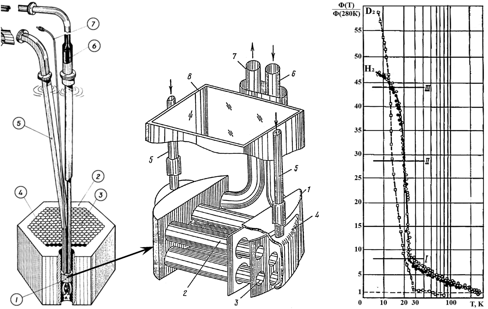
The next step in the UCN source development was the use of liquid hydrogen as a more effective converter [4]. The Small Liquid Hydrogen Source (SLHS) was installed in the beryllium reflector outside the core of the WWR-M reactor (Fig. 3, left and middle), in a thermal neutron flux of 6 × 1013 cm−2s−1. Key component of the SLHS was a heat exchanger in which the flow of cold helium from a HGU-500/15 refrigerator made it possible to condense 150 cm3 of normal hydrogen (75% ortho, 25% para). The total heat load on the low-temperature parts of the source was comprised of 0.3 W/g for the source material and 4 W/g for liquid hydrogen at 18 MW reactor power (which became available after an upgrade of the reactor). At a reactor power of 16 MW, the measured gain factor in the yield of UCNs was about 25, taking the UCN count rate at a hydrogen temperature of 280 K and a pressure of 3.2 bar for normalization. With a measured UCN flux of 4 × 10⁴ s−1, the SLHS operated at PNPI from 1980 to 1985 was at that time the most powerful UCN source in the world. Note that the SLHS also became a prototype for a CN source at the Budapest Research Reactor [15].
The SLHS was also used to perform first studies of UCN production in solid hydrogen and deuterium, replacing the LH2 used during normal source operation (Fig. 3, right). These works had to be carried out at a reduced reactor power of only 1.2 MW, because otherwise the refrigeration plant did not allow solidification of the converter material. For LH2 at the boiling point, UCN gain factors of 20–30 were measured. Lowering its temperature further down increased the gain factor to 40–43, which finally reached a value of 47 after solidification. For deuterium, the maximal UCN gain factor determined after solidification was 57. These experiments demonstrated for the first time the potential of sD2 for UCN production.
Fig. 3.
Small liquid hydrogen UCN source at the WWR-M reactor. Left: artistic view of the SLHS (1 – UCNS vessel; 2 – beryllium reflector; 3 – fuel elements; 4 – lead shield to decrease the heat load on the UCN source; 5 – UCN guide; 6 – helium cryo-pipes, 7 – hydrogen supply pipe). Middle: UCN source details (1 – cold helium buffer vessel; 2 – cold helium pipes; 3 – LH2 pipes; 4 – LH2 buffer vessel; 5 – hydrogen supply pipe; 6, 7 – cold helium inlet/outlet pipes, 8 – UCN extraction guide). Right: dependence of the UCN yield on the temperature of the hydrogen (∘ – while cooling down; ● – while warming up) and of the deuterium (□) in the converter (I – hydrogen condensation phase; II – increase of LH2 density with decreasing temperature; III – hydrogen crystallization phase).
2.3.Universal cold neutron source (UCNS)
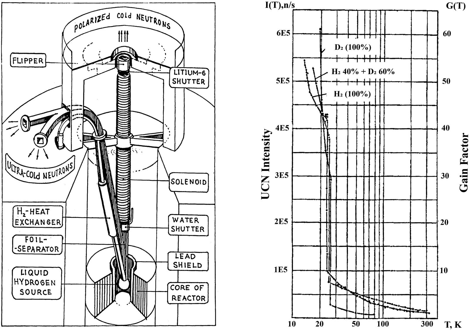
The aim to achieve still higher UCN fluxes led to the development of a new method for heat removal, which made it possible to place the next UCN source directly to the center of the WWR-M reactor core (Fig. 4, left) [5]. Key component was a thermosiphon described further below. The project was successfully implemented and provided high fluxes not only of UCNs, but also of cold, and polarized cold neutrons – that is why it was called a «universal» cold neutron source (UCNS).
The operation of the UCNS at the WWR-M reactor was launched at the end of 1985. A lead shield surrounded its one-liter LH2 moderator, to reduce the heat load on the low-temperature vessels. The thermal neutron flux incident on the source was 2 × 1014 cm−2s−1, and the total heat release in the source was 2 kW. For normal operation, a refrigerator plant with a cooling power of 3 kW at 20 K was used. The linear circulation velocity of LH2 in the source reached 1 m/s at full reactor power of 18 MW.
The temperature dependence of the UCN gain factor for gaseous and liquid H2 is shown in Fig. 4 (right), again referring to the UCN yield at a H2 temperature of 300 K at 3 bar. At 23.5 K and 2.3 bar, the UCN gain factor sharply increases due to the density increase of the moderator material on liquefaction, supporting thermalization of the incident neutron flux. A further decrease in the temperature of liquid hydrogen leads to an additional increase of the UCN output, with the gain factor reaching a value of 55. This source was also used for experiments with LD2 and H2-D2 mixtures.
Fig. 4.
Universal Cold Neutron Source at the WWR-M reactor. Left: artistic view of the installation. Right: temperature dependence of the UCN gain factor (referring to the UCN intensity at hydrogen at 300 K at 3 bar).
The operational principle of the thermosiphon for subcooled LH2 is shown in Fig. 5. Motion of the hydrogen is caused by hydrostatic forces, which are due to the density difference in the right and left parts of the loop. An increase of the heat supplied to the source also increases the speed of circulations, so that the system is self-regulating to an external heat load. The hydrogen in the left part of the loop is cooled down in the heat exchanger by cold helium from the cryogenic plant. While the reactor was operated at its full power of 18 MW, the speed of movement of LH2 along the loop tubes was 1 m/s. So, it turned out to be a very efficient circulation pump. Based on this principle of heat removal, PNPI designed and manufactured CN sources for the OPAL reactor (Lucas Heights, Australia) [8] and the CMRR (China Mianyang Research Reactor) [16], which are successfully operating right now.
Fig. 5.
Thermosiphon used to circulate the subcooled moderator material (LH2, LD2, or H2-D2 mixtures) of the UCNS.
2.4.Solid Deuterium Source (SDS)
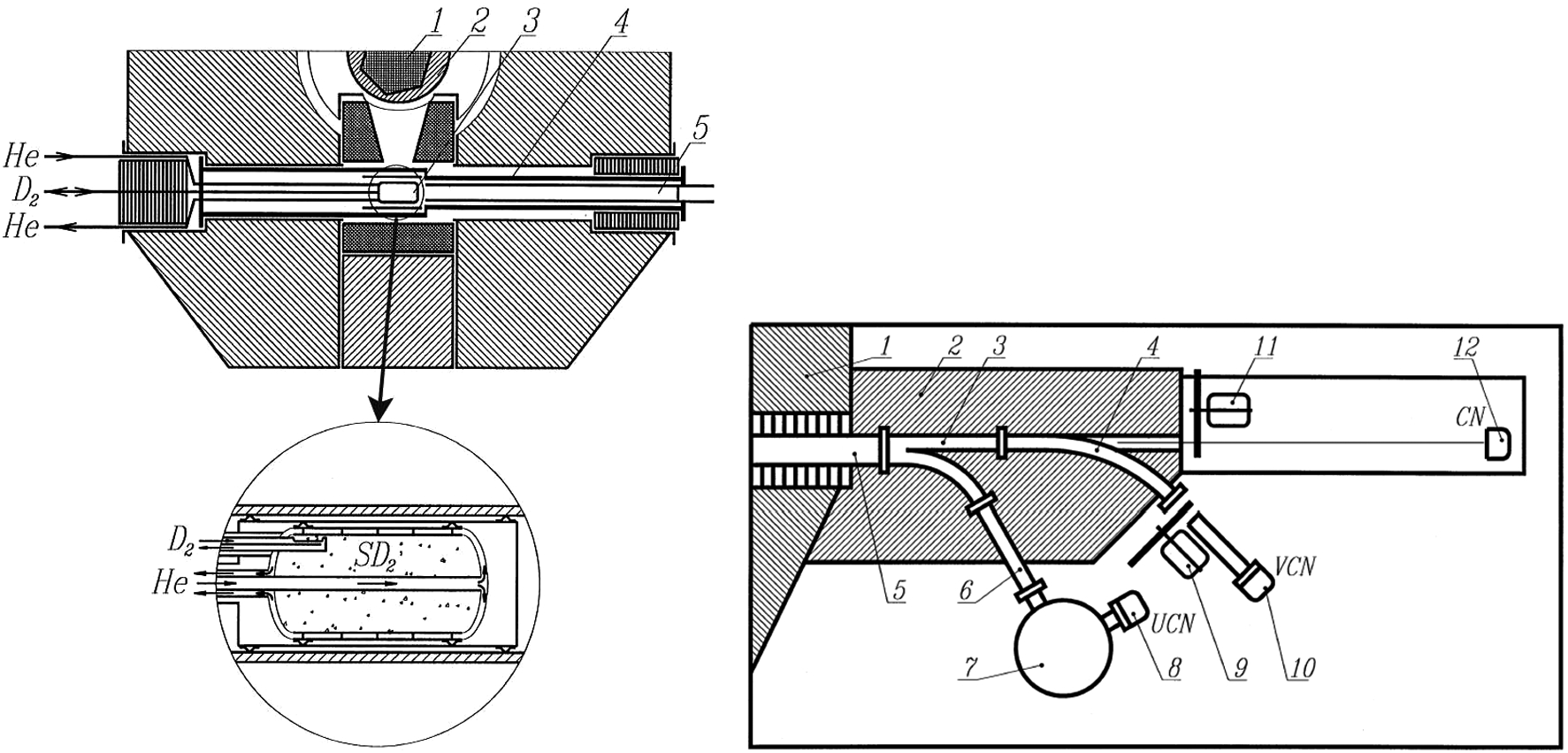
After the aforementioned successful studies with sD2 in the SLHS vessel, more detailed studies focused on developing for the WWR-M reactor a UCN source dedicated to this converter material [32]. As shown in Fig. 6 (left), this sD2 source called SDS was placed in a vacuum tube located inside a channel with an inner diameter of 210 mm which passed through the reactor’s thermal column. Its vessel made of 0.5 mm thick zirconium alloy had a cylindrical shape with elliptical ends. The length of the SLD cell was 350 mm, and its internal diameter was 160 mm. The source was cooled by a flow of liquid helium from a 150 W refrigerator. The weights of the zirconium cell and the sD2 during operation were 1.7 kg and 1 kg, respectively. The SDS was irradiated through a conical channel in the reactor’s thermal column, separated from the reactor core by a beryllium reflector. The distance from the core center to the SDS center was 150 cm.
The thermal neutron flux density in the center of the SDS was (9.2 ± 0.8) × 1010 cm−2s−1MW−1. The heat generated in the zirconium due to γ-rays amounted to (1.3 ± 0.2) × 10−3 Wg−1MW−1, while that due to scattering of fast neutrons in the deuterium was (9 ± 1) × 10−4 Wg−1MW−1. At 12 MW reactor power, the total heat load amounted to 37 W (20 W in the zirconium, 11 W in the deuterium and additional 6 W due to thermal heat flows from outside). The source was connected to a 6 m3 reservoir via a tube of 56 mm diameter. Cooling the SDS soaks deuterium from the reservoir, to condense and solidify in the source vessel, after which the remaining gas in the system settles at the saturated D2 vapor pressure. In the solid phase, the bulk volume of D2 was 85% of the source volume. Several measures were in place to keep the system always in a safe state. These included a fixed inventory of deuterium, a flow of warm helium through a tube located in the deuterium outlet channel to avoid blockages during warmup, and an always open vent for dumping the deuterium into the reservoir.
The neutron guide system of the SDS is shown in Fig. 6 (right). A straight guide with cross Section 70 × 120 mm2 connected to a guide system located outside the reactor shields, which consisted of a straight CN guide, a curved VCN guide and a curved UCN guide. The cross section of the straight and curved guides was 70 × 60 mm2. They were all made of highly polished stainless steel and coated with the alloy 58Ni-Mo providing a critical transverse velocity of 7.8 m/s for neutron reflection. Guide elements were connected by means of electron beam welding. The UCN trap (item 7 in the right part of Fig. 6) allowed us to select UCNs up to a critical velocity of 6.2 m/s defined by the trap material. The curved guide (4) selected the neutrons with wavelengths larger than 30 Å. Measurements of the VCN spectrum were carried out using a chopper (9) and a detector (10). The full neutron spectrum from the source was measured on the straight guide, also with the help of a chopper (11) and a detector (12).
Fig. 6.
Solid Deuterium Source at the WWR-M reactor. Left: location in a through-going channel of the reactor (1 – reactor core; 2 – beryllium reflector; 3 – SDS cell; 4 – source containment; 5 – UCN guide). Right: neutron guide system (1 – biological shield of the reactor; 2 – biological shield of the guides; 3 – straight CN guide; 4 – curved VCN guide; 5 – main guide from the SDS; 6 – curved UCN guide; 7 – UCN trap; 8 – UCN detector; 9 – VCN chopper; 10 – VCN detector; 11 – CN chopper; 12 – CN detector).
Experimental results on the neutron yields from the SDS at different ranges of wavelength are shown in Fig. 7. The left part of this figure presents the yields versus D2 pressure in the system, normalized to the yield from LD2 at a temperature of 20 K, calling this quantity the «relative gain factor». The pressure of 128.5 torr corresponds to the triple point at 18.7 K, where the transition to the solid phase occurs. Figure 7 (middle) demonstrates the same relative gain factor, but in dependence on the temperature as derived from the saturated vapor pressure. For UCNs, a maximal value close to 10 occurs at 10 K. The UCN yield increases on solidification of the D2, because the transitive atom motions in the liquid freeze out and the cross-section for inelastic UCN scattering decreases, so that the source becomes more transparent. However, further reduction of the temperature below 10 K would not be effective, since the total cross section contains a then dominating constant contribution,
The strong dependence of the UCN gain factor on
Fig. 7.
Relative and absolute (see text) gain factors of UCN, VCN and CN production in a range of temperatures/pressures near solidification. (Graphs taken from references [35]) left: as a function of D2 pressure in the buffer tank. Middle: as a function of temperature. Right: temperature dependence of the absolute gain factor of the SDS.
![Relative and absolute (see text) gain factors of UCN, VCN and CN production in a range of temperatures/pressures near solidification. (Graphs taken from references [35]) left: as a function of D2 pressure in the buffer tank. Middle: as a function of temperature. Right: temperature dependence of the absolute gain factor of the SDS.](https://content.iospress.com:443/media/jnr/2022/24-2/jnr-24-2-jnr220007/jnr-24-jnr220007-g007.jpg)
The development of the SDS, despite all its successes, also revealed some issues of sD2 as a UCN source material:
The presence of protium atoms (1H) in the D2 may strongly reduce the UCN output. Its maximal admissible concentration in an sD2 UCN source is 0.1–0.2%.
The ratio of amounts of ortho and para D2 significantly affects the cross section for the long-wavelength part of the neutron spectrum. Experiments carried out at PNPI to study the transmission of very cold neutrons through sD2 have shown that, for neutron wavelengths around 150 Å, the total cross section for D2 with 66% in the ortho state is 1.5 times greater than for almost pure ortho D2 (93% in the ortho state) [36]. Ortho D2 is hence a necessity for this type of UCN source.
Uneven density distribution («snowy-ness») of sD2 due to thermal stress can lead to UCN scattering by such inhomogeneities. For effective path lengths between inhomogeneities smaller than the mean free path, as determined by the macroscopic cross sections for inelastic scattering and UCN capture, the gain factor no longer increases with decreasing temperature [33].
After successful demonstration of the SDS at the WWR-M reactor in 1995, it was proposed to use sD2 at spallation neutron sources based on pulsed accelerators [34]. Solid D2 as a UCN converter material had received great interest after the «The First UCN Workshop» held in 1999 in Pushkin, Russia. Experimental facilities based on sD2 were subsequently constructed at the Los Alamos National Laboratory [30] and at the PSI accelerator [6].
3.Ultracold neutron sources based on superfluid helium at PNPI
3.1.Brief historical background and operational principle
The history of UCN source developments at PNPI continues even right now, with a new development of a high-intensity UCN source using superfluid 4He (He-II) as a converter. Neutron scattering in He-II was analyzed theoretically by Ahiezer and Pomeranchuk as early as 1945 [2], which may have inspired Zeldovich in 1959 to consider this completely neutron absorption free medium for UCN production [54]. Likely, due to the challenge to maintain this cryogenic liquid near the core of a nuclear reactor, this idea was not immediately pursued further in Russia. In 1977 then, Golub and Pendlebury published the idea to exploit the dispersion of coherent excitations in He-II for production of UCNs [14], where they also noted the possibility to produce large UCN densities in a He-II converter installed at an extracted cold neutron beam.
The basic mechanism of UCN production in He-II exploits the Landau dispersion curve relating the energy and momentum of excitations (phonons, rotons) of He-II. At the point where it intersects with the parabolic dispersion curve of the free neutron, at a neutron wavelength of 8.9 Å, the neutron may convert into a UCN in a coherent inelastic process by emitting a single phonon, thereby imparting most of its energy of 1 meV to the quantum liquid. The dominant processes leading to up-scattering back to CN energies involve two quasiparticles in He-II and become negligible with respect to neutron beta decay (
To exploit such long time constants requires other UCN losses from the He-II converter to be suppressed as well. On the one hand, there are losses at the walls of the converter vessel, which can be kept small by a proper choice of the material (at an extracted beam one may also use a magnetic reflector [57]). On the other hand, one needs to remove the strongly neutron absorbing isotope 3He from the converter below a relative atomic abundance of
Developments of UCN sources based on He-II are currently advancing in various countries, including Canada, France, USA and Japan (see Table 2). While the principle of UCN production by cold-neutron conversion in He-II has experimentally been well established in several laboratories on the scale of prototypes, the next major step will be its implementation in the harsh environment near the core of a high-flux neutron source. The current developments pursued at PNPI aim towards this goal.
3.2.UCN source project at the WWR-M reactor
In the mid-2000s, it was proposed to implement a UCN source based on He-II at the WWR-M reactor in its so-called thermal column [37]. This void with a diameter of one meter adjacent to the reactor core offers a high neutron flux and plenty of space to host a large cryogenic installation. The projected source assembly is shown on the left side of Fig. 8. A water-cooled lead shield on the front part of the source assembly reduces the heat load on the He-II due to nuclear radiations. The vacuum container is cooled by heat conduction through the metal and graphite from the lead shield, which is sufficient to keep the temperature below 80°C.
Fig. 8.
Proposed implementation of a He-II UCN source in the thermal column of PNPI’s WWR-M reactor. Left: horizontal cut view. Right: heat loads on various elements of the UCN source at 16 MW reactor power.
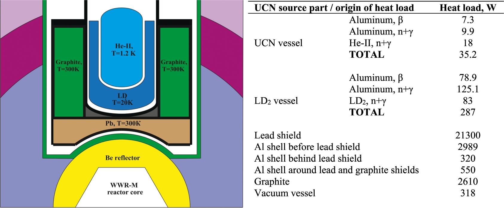
An analysis of source performance to be expected for this source model showed that LD2 would be the best choice of a material for the pre-moderator [28]. The latter needs to be enclosed in a double-walled aluminum vessel and cooled down to 20 K by helium from a refrigerator. The central bore in the LD2 pre-moderator contains the cylindrical UCN converter vessel with a diameter of 300 mm, a length of 500 mm and a wall thickness of 2 mm, which during source operation is filled with He-II at 1.2 K. The front wall of the chamber is located at a distance of 92 cm from the center of the reactor core.
The inner surface of the UCN vessel is foreseen to be coated with a 3–5 nm thick 58Ni-Mo alloy, for which UCNs have a critical reflection velocity of 7.8 m/s. UCNs can be extracted via a 58Ni-Mo-coated neutron guide, separated from the source by an 100 μm aluminum foil (foil of the minimum thickness, which will not break down under the pressure drop between the UCN chamber and UCN neutron guide). The thicknesses of the graphite moderator, the lead shield and the LD2 pre-moderator were chosen to obtain the maximal possible cold neutron flux in the UCN converter vessel, while keeping the thermal load on the coldest part of the source below 40 W.
Monte-Carlo simulations, using the program MCNP, determined neutron fluxes and heat loads. The latter are listed in the table on the right side of Fig. 8, quoting 28 kW on the source components at ambient temperature, 287 W on the LD2 pre-moderator, and 35.2 W on the filled UCN vessel; all at a reactor power of 16 MW. Calculations showed that UCN densities of about 104 cm−3 might be achievable in the experimental trap of an EDM spectrometer [44].
For implementation of this project, modern cryogenic and vacuum equipment was purchased and put into operation at PNPI. It consists of a helium liquefier with a capacity of 100 liters per hour (Linde model L-280), a helium refrigerator providing 3000 W at 20 K, and a helium pumping station enabling circulation of 3 g helium per second at 50 Pa.
3.3.Full-scale model of the UCN source
Operation of the UCN source as described above requires a technological complex, capable to maintain the He-II filled UCN converter close to 1 K, under the heat load due to the radiations from the reactor. For validation of the feasibility of such a UCN source, we created a full-scale model, respecting the geometric conditions in the thermal column of the WWR-M reactor. This mockup included all the cryogenic and vacuum facilities as needed in its designated position. Thermal studies were performed using a heater, which imitated the heat flow from the reactor radiation. To make these studies as realistic as possible, a thermal screen at 20 K surrounded the entire low-temperature part of the model. The goals of experiments with this setup were:
to validate the chosen technology for producing He-II at 1.2 K,
to confirm the possibility to remove up to 60 W of heat loads from the He-II,
to purify helium from the strongly neutron absorbing isotope 3He,
to gather experience in operating the whole source complex before moving it to the reactor.
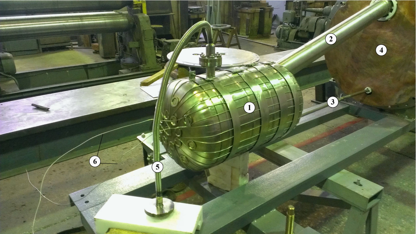
Figure 9 shows a schematic of the technological complex implemented at PNPI. It includes the mockup of the UCN converter, a helium cryostat, a helium liquefier (L-280), a helium refrigerator (TCF-50), a helium gas pumping station, a helium storage system, and auxiliary technological and control systems. Figure 10 shows some photos of the whole technological complex, and Fig. 11 the UCN converter vessel.
Fig. 9.
Technological complex of the UCN source mockup (see text).
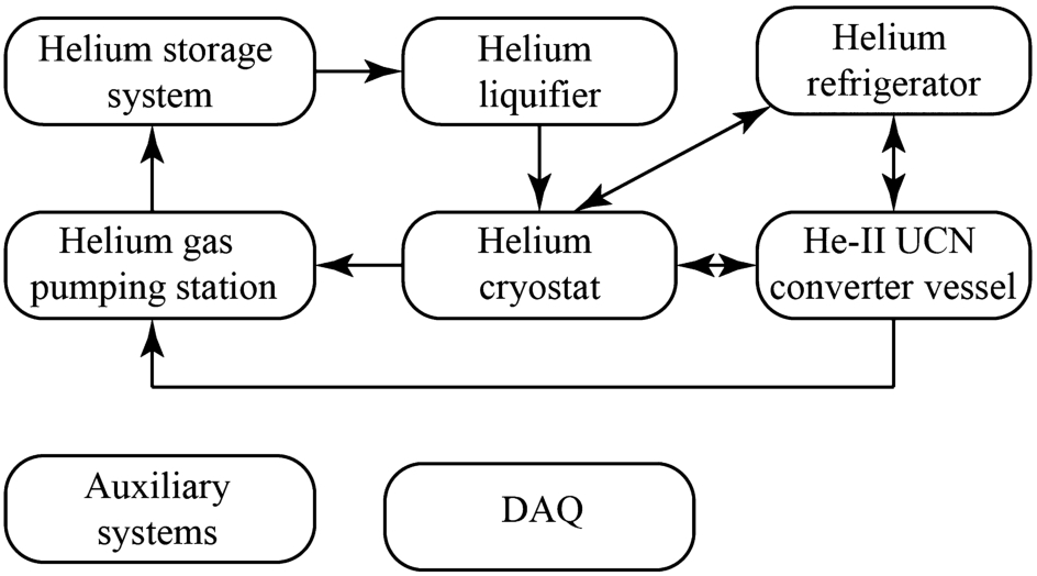
Fig. 10.
UCN source mockup at the WWR-M reactor (1 – helium liquefier L-280; 2 – helium refrigerator TCF-50; 3 – helium cryostat; 4 – UCN source model; 5 – pumping unit for isotopically pure 4He gas; 6 – helium vapor heaters; 7 – liquefier control cabinet; 8 – refrigerator control cabinet; 9 – helium roots pumps).
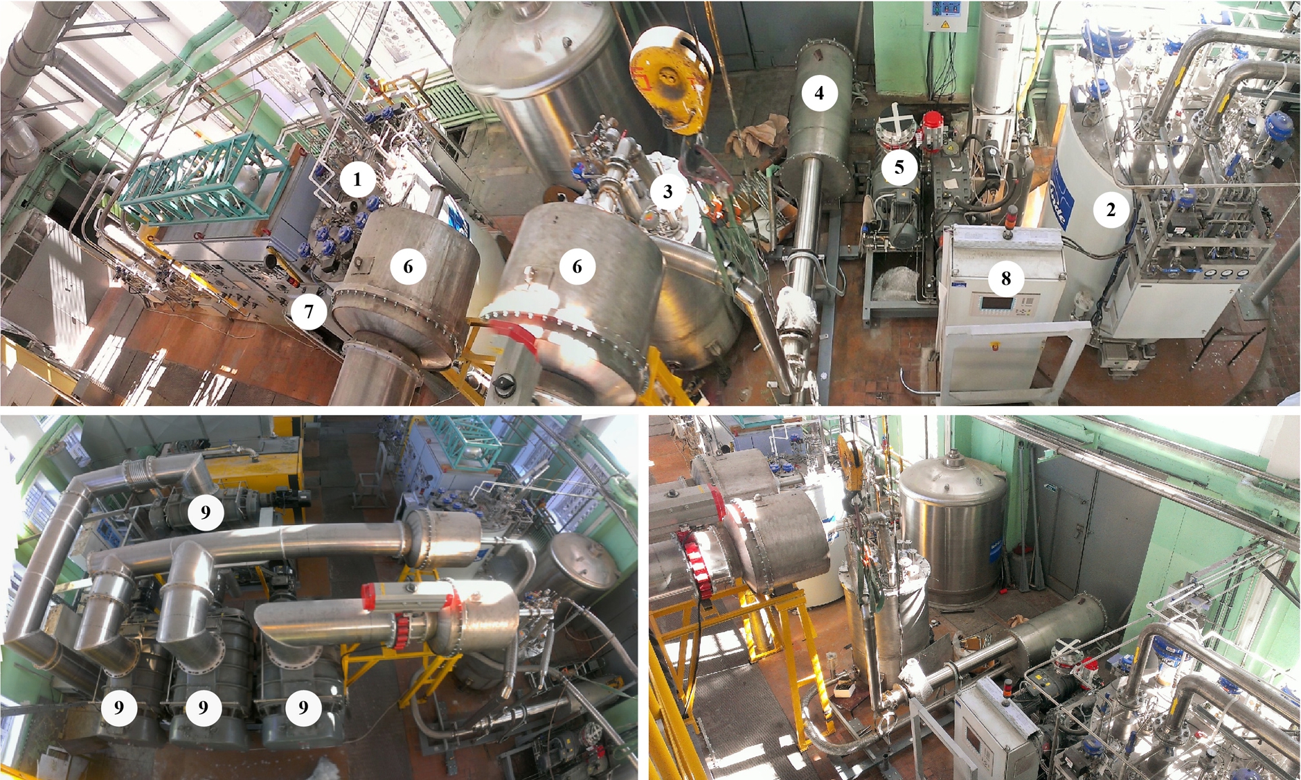
Fig. 11.
UCN converter vessel mockup (1 – helium vessel, 2 – helium vapor pipe, 3 – He-II supply pipe, 4 – heat screen, 5 – wire pipe, 6 – 250 Ohm nichrome electrical heater). The He-II vessel has a diameter of 300 mm and a length of 500 mm. The chamber is equipped with a helium level gauge and a temperature sensor.
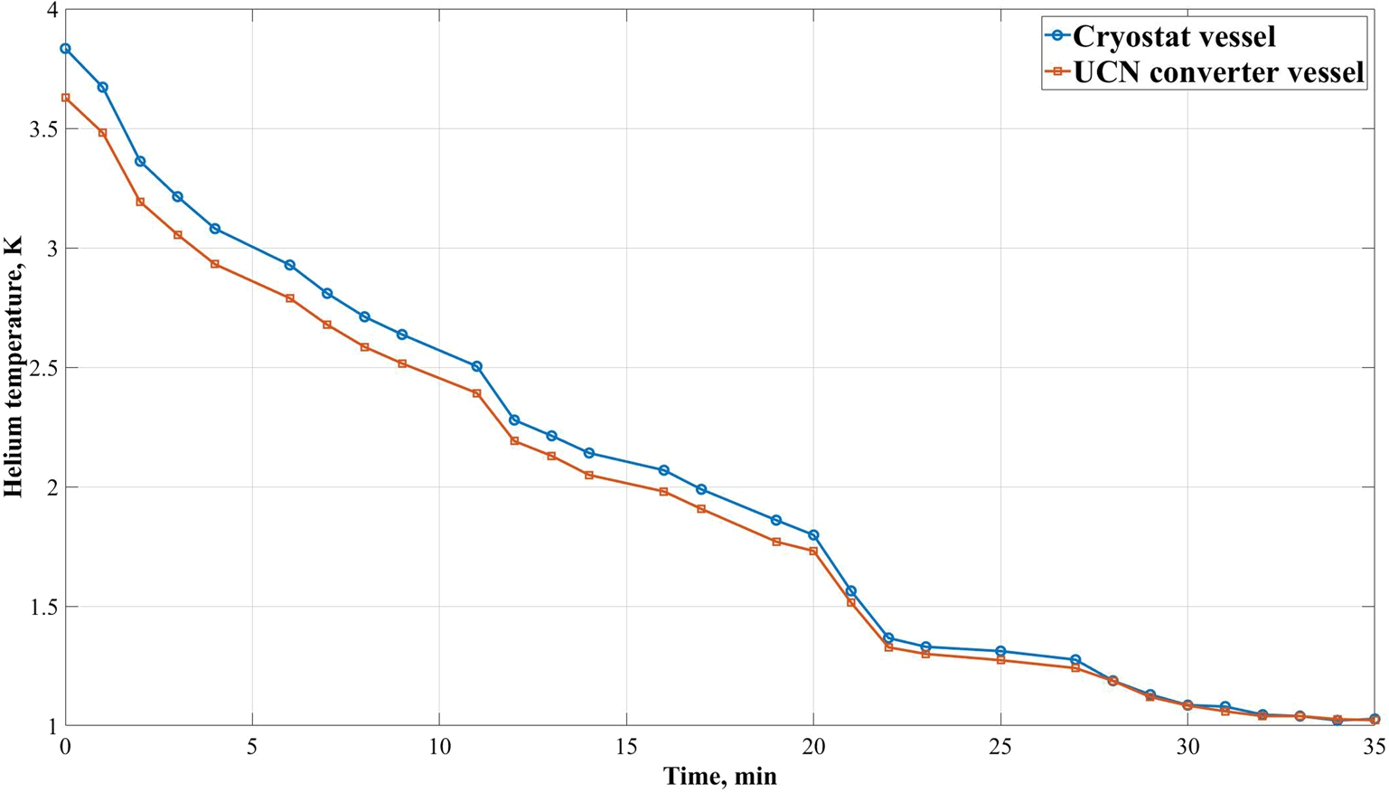
As a first step in preparation of a cooldown of the source mockup, the helium gas inventory (corresponding to 150 liters of liquid at standard conditions) is circulated through a cryogenic absorber in a cold trap filled with liquid nitrogen, which removes most of the nitrogen and water impurities from the helium. Then, the helium refrigerator TCF-50 is launched to cool the heat shields to 20 K. Next, the L-280 liquefier is launched. Temperatures below 4 K are attained using the helium gas pumping station, which includes four Edwards HV-30000 roots pumps, each with nominal pumping speed of 30000 m3/h. This reduces within about 40 minutes the helium temperature to below 1.1 K (see Fig. 12).
Fig. 12.
Cooldown of the liquid helium, using the system of roots pumps (see text).
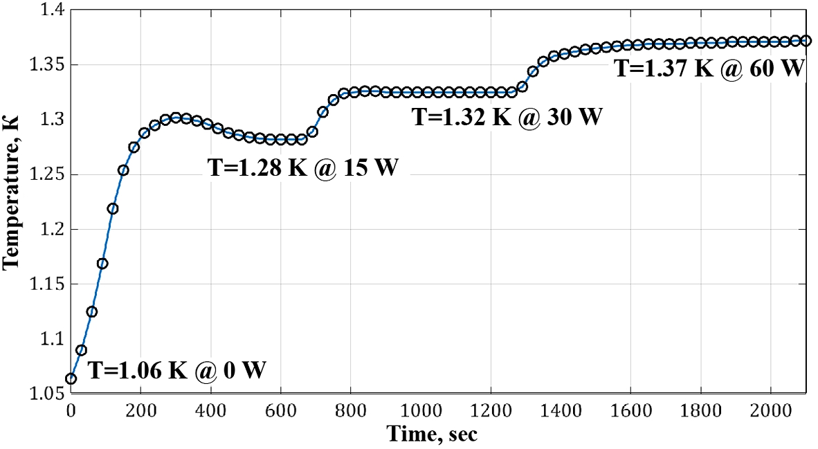
The main goal of the first cooldown test experiment was to determine the real temperatures of the He-II in the converter at various heat loads, i.e., 0, 15, 30, and 60 W. The latter exceeds the calculated value for the heat load at the WWR-M reactor operated at a power of 16 MW, which is expected to be 52 W (broken down to 35.2 W due to reactor radiation, 0.8 W through thermal bridges, and 16 W due to heat carried by the constant inflow of liquid helium at 4.2 K to be cooled down to the converter temperature). Each level of the heater power was maintained for 10 minutes, which was sufficient to stabilize the temperature in the cryostat and the converter vessel. Figure 13 shows the experimental results, which demonstrate the feasibility of the studied UCN source at the WWR-M reactor. More details about this experiment can be found in Ref. [41].
Fig. 13.
Evolution of the liquid-helium temperature during the experiment with a resistive heater (see text). The values of pressure measured at the inlet of the pumping station were: 0.5 Pa at 0 W, 5.7 Pa at 15 W, 14.6 Pa at 30 W, and 24 Pa at 60 W power provided by the heater.
This experimental confirmation of maintaining superfluid helium under such high thermal loads opens up new possibilities in the technology of producing UCN sources. While sources of this kind were previously located under conditions of low heat inputs and, correspondingly, low neutron fluxes, it is now possible to significantly increase the UCN density by placing the converter in close proximity to a strong neutron source.
3.4.UCN sources on cold neutron beams at PIK reactor
In 2020, a Federal Program was implemented for creating experimental facilities for the PIK reactor. One of the main facilities to be constructed within this Program is a new He-II based UCN source for research in fundamental physics. Afterwards, the decision was taken not to relaunch the WWR-M reactor anymore. This motivated us to study possibilities to place a He-II converter in a cold neutron beam at the PIK reactor [38].
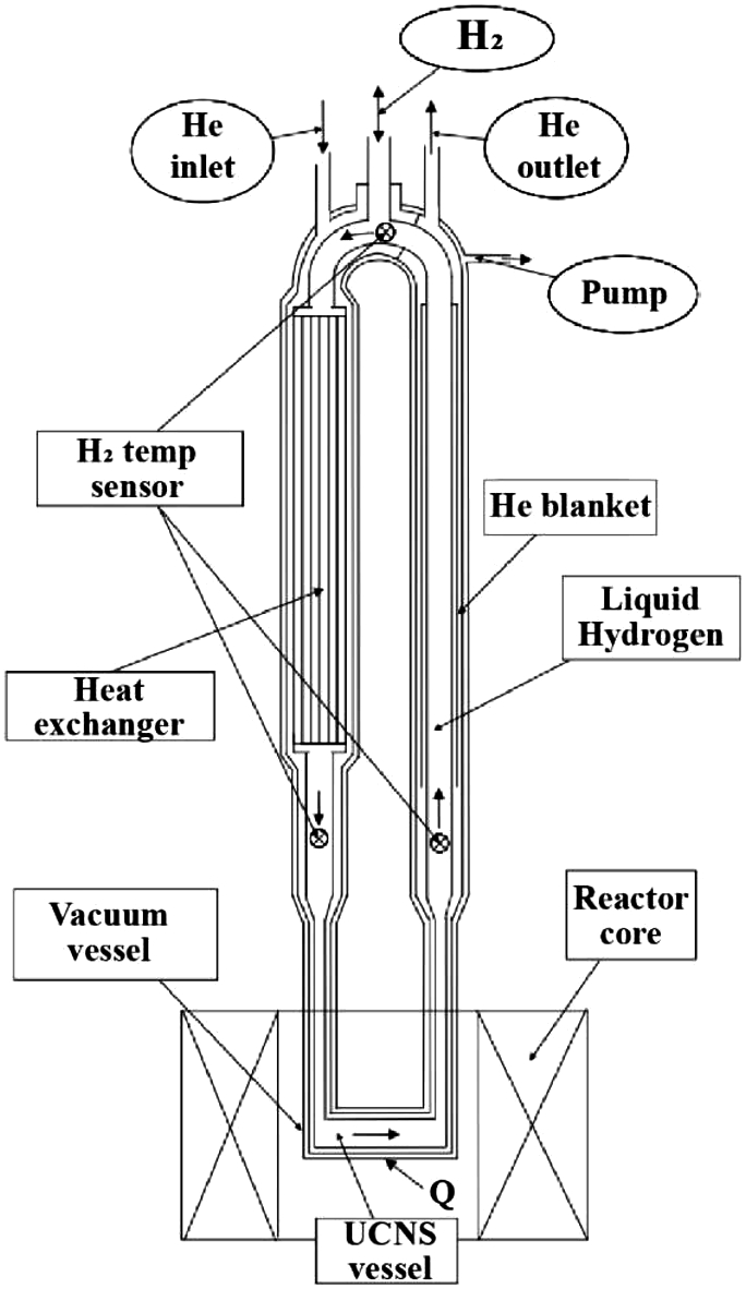
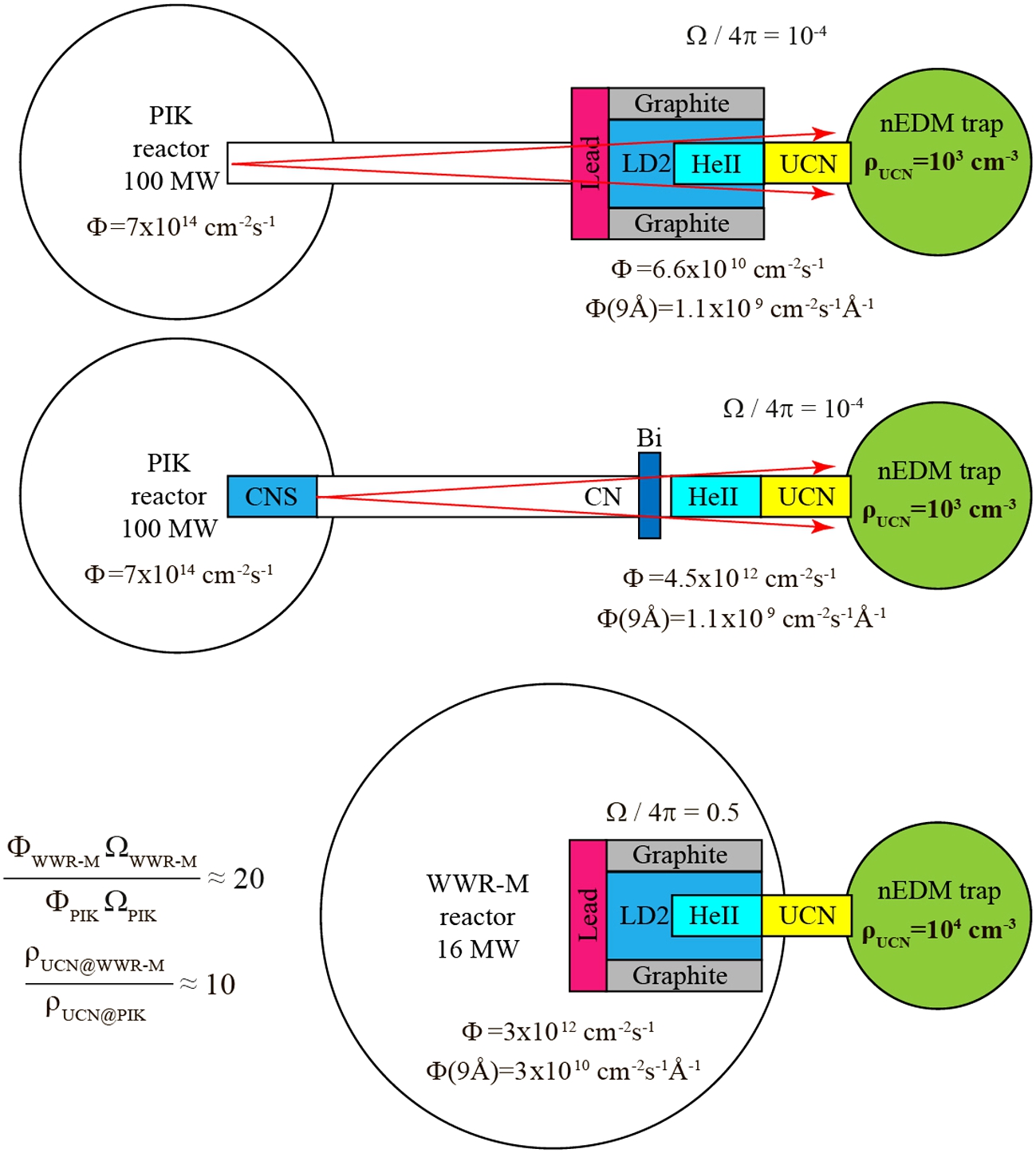
The main differences between the UCN sources studied for the PIK and WWR-M reactors are shown in Fig. 14. No in-pile position is available at the PIK reactor right now, so that a UCN source based on He-II has to be located on an extracted neutron beam, at a minimum distance of 3 meters from the reactor core, while in the thermal column at the WWR-M reactor this distance would have been only 40 cm. At a 3-meter distance from the neutron source, the solid angle is
Due to this lower flux incident on the UCN source, the total heat load on the He-II will be 10 times lower than it would have been at the WWR-M reactor. Moreover, it can be further reduced by placing a block of polycrystalline bismuth in front of the source, serving for protection against gamma radiation. A 100 mm thick block would reduce the heat release in the UCN source vessel by 30 times. This will greatly simplify the technique to maintain the converter at 1 K and correspondingly reduce the cost of the necessary cryogenic and vacuum equipment. Accordingly, the temperature of He-II can be lowered significantly, with a positive impact on the UCN density. Results of a work studying bismuth filters are given in Ref. [39].
Taking all effects into account, the UCN density attainable in an external experimental trap drops by one order of magnitude when moving from the «in-pile position» at the WWR-M reactor to an «in-beam position» at PIK. It is noteworthy that simulations of two rather different schemes of a UCN source, with a cold source implemented inside or outside the PIK reactor (see Fig. 14) predict the same UCN density. However, operating a CN source in-pile would be very expensive due to the necessary powerful cryogenic equipment able to remove about 7 kW of heat loads. The next subsection presents our currently preferred solution for a UCN source at PIK.
Fig. 14.
Schematic comparison of UCN source implementations (in «zero approximation») at the PIK reactor with a CN source in-beam (upper figure) and in-pile (middle), and at the WWR-M reactor (lower). Φ denotes the thermal neutron flux.
3.5.UCN source on the thermal neutron beam GEK-4 at PIK reactor
This UCN source will be installed on the thermal neutron beam channel GEK-4. With its inner diameter of 220 mm, it is the largest available channel of the PIK reactor (see Fig. 15, left). Our plan is to create a 1-meter wide aperture in the outer PIK biological shielding. Similar to the source design for the WWR-M thermal column, this hole is large enough to host the entire UCN source, with a graphite reflector, a low-temperature pre-moderator and the He-II converter, everything included in an outer vacuum vessel. The front part of the UCN source will start directly after the flange of the GEK-4 channel. The thermal neutron flux density in the He-II in this geometry is expected to be 6.6 × 1010 cm−2s−1.
The works on optimization of the UCN source included analyses of the source configuration as shown in Fig. 15 (left), but also of a so-called «inverse pre-moderator design». In this latter scheme, the low-temperature pre-moderator is placed behind the He-II, therefore mainly working as a reflector, which returns slowed-down CNs to the He-II source chamber. Liquid D2 and solid methane were considered as pre-moderator materials. Preliminary calculations showed that LH2 would give a significantly lower 9 Å neutron flux at the same heat load, and was therefore discarded. The use of solid methane would entail strict measures to comply with government safety rules, as clogging of cavities with solid methane can lead to disruption of the pre-moderator vessel. We have therefore decided to use LD2 as a pre-moderator.
Fig. 15.
UCN source implemented in the horizontal experimental channel GEK-4 at the PIK reactor. Left: source model studied by MCNP calculations (see text); 1 – UCN converter vessel containing isopure superfluid 4He; 2 – heat exchanger containing helium at 1 K for cooling the converter vessel; 3 – LD2 pre-moderator; 4 – graphite; 5 – lead shield; 6 – aluminum biological source shield; 7 – steel reactor biological shield; 8 – borated polyethylene reactor biological shield). Right: optimized parameters of the UCN source (for 100 MW reactor power).
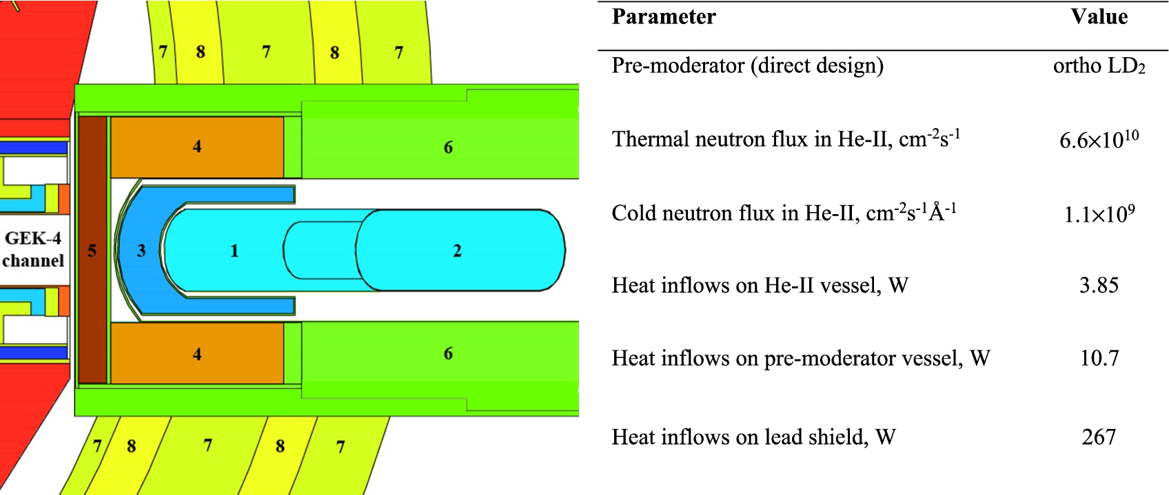
Neutron flux densities and heat loads on the main parts of the optimized UCN source are summarized in Fig. 15 (right). Compared to the WWR-M project described in Section 3.2, heat loads on the low-temperature parts of the source are sufficiently low to use gaseous helium as a coolant for the lead screen. Helium, compared to water, has a lower neutron cross section, which gives 1.57 times more 9 Å neutrons in He-II. The results of the thermal calculation showed that to ensure the proper thermal condition of the lead shield, a minimum helium mass flow rate of 1.1 g/s is required, at which the temperature of the shield will be 59.5°C, and the maximum temperature of the aluminum vacuum vessel will be 58.8°C.
The optimization of the UCN source for GEK-4 resulted in the same design of the pre-moderator part (with the same material composition) as for the WWR-M reactor. However, at this new location, the heat release in the pre-moderator vessel has noticeably decreased from 287 W to now 10 W. In addition to changing the material of the UCN source chamber (from AlMg5 to stainless steel), the design of the helium part itself was also changed: a heat exchanger was added, the evacuation pipeline was removed, the diameter of the neutron guide was increased, etc. The total value of heat loads not related to radiations from the reactor (i.e., those left due to thermal bridges and thermal radiation) was calculated to be 3 W. Thus, the total heat load on the helium part, including the heat from the reactor at 100 MW, will be 6.85 W. This heat will be removed through a heat exchanger, using 4He as a coolant.
The UCN density calculated for this source would be 2.2 × 103 cm−3 in case of the closed UCN converter. However, we plan to work in the mode of filling experimental traps with UCN together with the source, so the UCN density in traps is of practical importance. For predictions of the UCN fluxes and densities available in an experimental setup placed in the main hall of the reactor to search for the neutron EDM, a Monte-Carlo model has been developed. The model is based on realistic assumptions on UCN transport in the guide system connecting the source with the experiment and also takes into account the presence of 2 aluminum foil (100 μm each) that separate the volumes of the UCN source, neutron guide and nEDM facility. The simulations predict a UCN density of 200 cm−3 in the setup. This density will allow us to achieve a sensitivity of
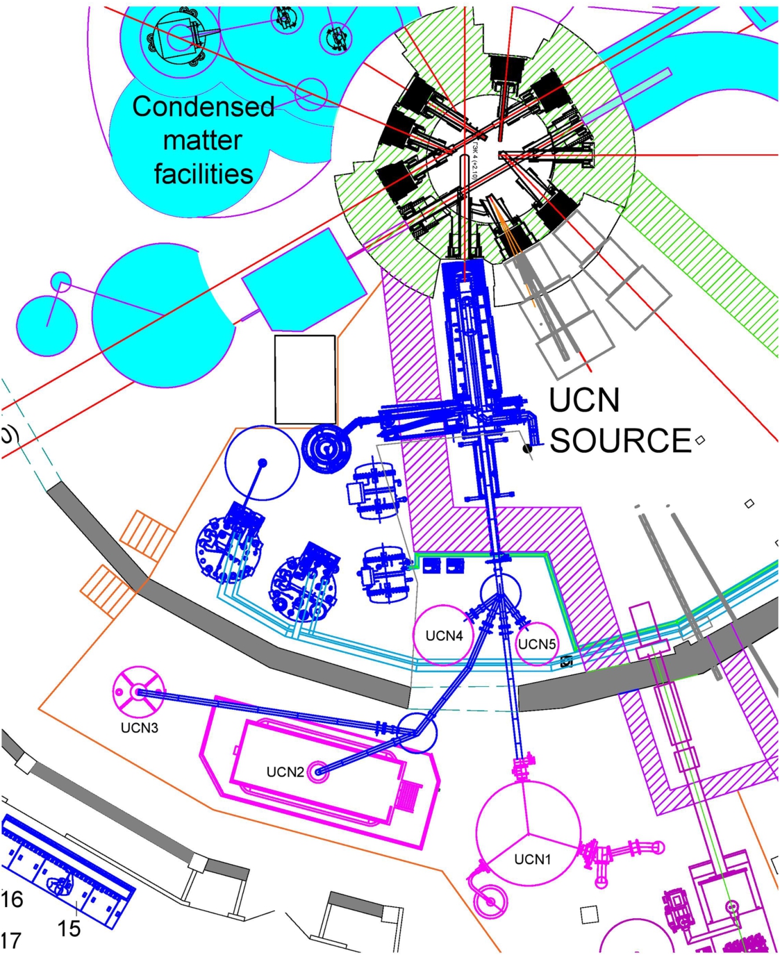
In general, a broad research program is planned. The UCN guide system has been designed to feed up to five experimental facilities [43]. At the start of its operation, it is planned to equip the UCN source with experimental setups already available at PNPI: an nEDM spectrometer [40] and two neutron lifetime experiments, one with a gravitational [42] and one with a magnetic trap [10]. In Fig. 16 the corresponding beam lines are designated as UCN1, UCN2 and UCN3, respectively.
Fig. 16.
Floor plan showing the UCN source at GEK-4 at the PIK reactor with its UCN guide system (in navy blue) and beam ports to five locations for experiments (in magenta); UCN1 – nEDM experiment, UCN2 – gravitational trap, UCN3 – magnetic trap, UCN4 – free, UCN5 – free.
4.PNPI proposals for UCN sources at the ESS
From our experience acquired at PNPI we can conclude that:
A sD2 based UCN source is good for pulsed neutron sources, mainly because of the possibility of cooling down the sD2 in the absence of a neutron beam (during zero heat loads).
A He-II based UCN source is good for stationary neutron sources, mainly due to the absence of neutron absorption in He-II.
However, due to its high pulse frequency, the ESS is practically stationary for UCNs, and therefore He-II will be more suitable. This section presents ideas for He-II based UCN sources in several locations at different distances from the planned LD2 lower moderator of the ESS (see the workshop contributions by Zanini et al. [53] and Oden [27], which present more details about these locations).
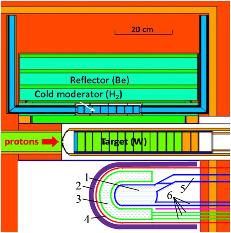
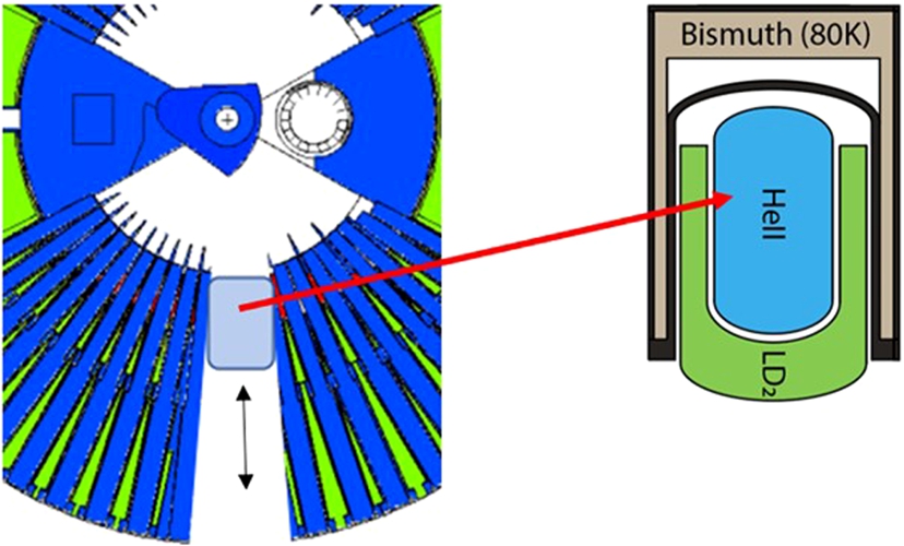
4.1.Option 1 – inside twister
From our simulations of the various source options for the WWR-M and PIK reactors as described in Section 3, we expect the largest UCN fluxes achievable for a UCN source with a pre-moderator placed closest to the primary neutron source. At the ESS, this would mean to implement the source inside the twister, replacing the foreseen LD2 cold source (see Fig. 17). This location will obviously be accompanied by huge heat loads on the He-II converter and its vessel. If it does not exceed 150 W, a bismuth screen surrounding this vessel (see Fig. 18) might reduce it to a level of 5–8 W, at which modern cryogenic and vacuum equipment as described above would be able to keep the He-II converter close to 1 K. It is however most likely that the heat load will be too high, so that the He-II converter will have to be located outside the LD2 cold source, but then in closest possible vicinity. This situation is discussed in the next subsection.
Fig. 17.
Option 1 – inside twister (1 – He-II converter; 2 – bismuth shielding with water cooling, which will also thermalize fast neutrons; 3–LD2 pre-moderator; 4 – vacuum vessel; 5 – UCN guide; 6 – cryogenic supply lines).
4.2.Option 2 – in a standard beam port viewing the LD2 cold source
In this case, the maximal lateral thickness of the He-II converter cannot exceed 100 mm. Depending on the total heat loads, its length can be 2–3 meters. The heat load can be further reduced by a block of polycrystalline bismuth in front of the converter, serving for protection against gamma radiation. The inner part of the beam port can be covered with a CN reflector. It would be useful to foresee some flexibility for placement of the UCN source along the axis of the beam port, for optimization of the CN yields and the heat loads. This scheme for a UCN source is similar to what we proposed for the PIK reactor with a cold neutron source inside reactor (see Section 3.4).
Fig. 18.
Option 2 – in a standard beam port.
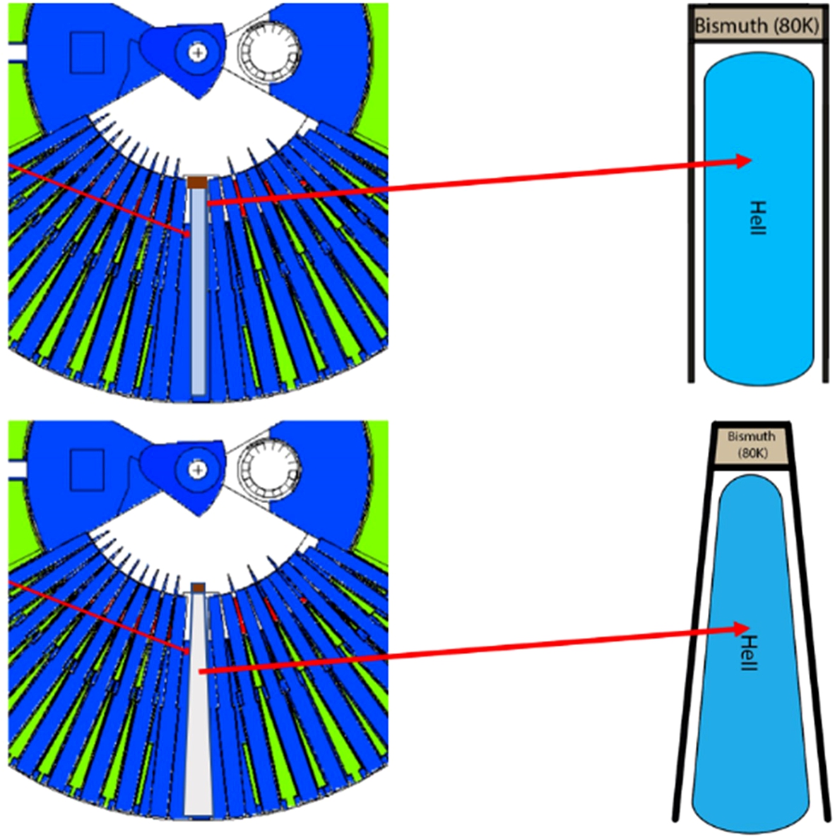
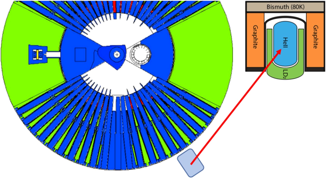
4.3.Option 3 – in the large beam port
With respect to heat loads and neutron fluxes, this solution looks most realistic and promising of all options discussed here (see Fig. 19). Moreover, the data presented in Ref. [53] indicates a heat load of only 8.4 W on a 57.6 liter He-II converter and its vessel, which would be manageable for the cryogenic complex described in Section 3.3. We would recommend further optimization of this geometry, for which we expect the inverse scheme of the pre-moderator to be advantageous.
Fig. 19.
Option 3 – in the large beam port.
4.4.Option 4 – outside the shielding monolith
This case corresponds to the scheme of a UCN source coupled to a cold source at the PIK reactor (see Section 3.4). We propose this option only as a solution if for any reason none of the others can be done. An advantage of this option would be that it can be realized at any time, even after the actual launch of the ESS. Note the «inverse scheme» arrangement of LD2, shown in Fig. 20. Working as a reflector instead of a CN generator, one may expect a significant increase of 9 Å neutrons impinging on the He-II converter. However, this option will unfortunately most likely provide the lowest UCN densities, due to the large distance of more than 5 meters from the CN source.
Fig. 20.
Option 4 – outside the shielding monolith.
5.Conclusions
Ultracold neutrons play a major role in scientific research on the physics of fundamental interactions. The main current topics addressed with UCNs are searches for a nonzero electric dipole moment of the neutron, exact determination of the neutron lifetime and its beta asymmetry, and searches for dark matter. Experiments complement much more expensive facilities and megaprojects at modern high-energy particle colliders. Over the past 50 years, the UCN density has been increased by 8 orders of magnitude. Efforts towards further improvements are made all over the world.
Developments of new technologies for UCN production are needed to enable further progress in the aforementioned projects, which are mostly limited by counting statistics, but might also open up great new opportunities in the field of fundamental physics. The current status is that effective methods using low-temperature neutron converters, such as sD2 and He-II, have been well studied. At PNPI, we have demonstrated a full-scale model of a UCN source able to remove a heat load of 60 W from He-II at a temperature of 1.37 K. This has confirmed the practical possibility to implement low-temperature converters in strong neutron fluxes with large heat inflows.
Nowadays, there are two main ways to obtain high-intensity neutron fluxes – the spallation neutron source at a pulsed accelerator and the stationary nuclear research reactor. The studies carried out at PNPI have shown a high UCN production efficiency of sD2 at pulsed sources and of He-II at research reactors. An advantage of pulsed neutron generation is the possibility to cool down the sD2 during absence of the neutron beam, where heat loads become marginal. However, as for UCN the ESS is practically stationary due to its high frequency of pulses, UCN generation in He-II seems to be the preferable solution, due to the absence of neutron absorption in He-II.
Based on our experience, we have proposed He-II based source options for the ESS. For each choice of a preliminary UCN source design, careful calculations of the heat loads to all parts of the source need to be performed. Once sure that one can remove the heat using state-of-the-art cryogenic facilities, some optimizations of the source performances need to be done, addressing choice of materials and geometrical parameters of the source. An important goal is to keep the UCN source accessible for maintenance and upgrades, for which reason it should be removable and made of materials with still manageable activation under neutron irradiation.
References
[1] | C. Abel et al., Measurement of the permanent electric dipole moment of the neutron, Physical Review Letters 124: ((2020) ), 081803. doi:10.1103/PhysRevLett.124.081803. |
[2] | A.I. Ahiezer and I.Y. Pomeranchuk, On the scattering of neutrons with an energy of several Kelvin in liquid helium II, JETP 16: ((1945) ), 391. |
[3] | I.S. Altarev et al., A search for the electric dipole moment of the neutron using ultracold neutrons, Nuclear Physics A 341: ((1980) ), 269–283. doi:10.1016/0375-9474(80)90313-9. |
[4] | I.S. Altarev et al., A liquid hydrogen source of ultra-cold neutrons, Physics Letters A 80: ((1980) ), 413–416. doi:10.1016/0375-9601(80)90784-7. |
[5] | I.S. Altarev et al., Universal liquid-hydrogen source of polarized cold and ultracold neutrons at the VVR-M reactor of the Leningrad Institute of Nuclear Physics, Soviet Journal of Experimental and Theoretical Physics Letters 44: ((1986) ), 344. |
[6] | F. Atchison et al., An ultracold neutron facility at PSI, PSI Scientific Report 1 (2002). doi:10.1016/j.physletb.2004.04.048. |
[7] | C.A. Baker et al., Experimental measurement of ultracold neutron production in superfluid 4He, Physics Letters A 308: ((2003) ), 67–74. doi:10.1016/S0375-9601(02)01773-5. |
[8] | M. Bonneton et al., Installation and testing of the OPAL (ANSTO) Cold Neutron Source, in: 10th Meeting of the International Group on Research Reactors, (2005) , pp. 256. |
[9] | E. Chanel et al., Concept and strategy of SuperSUN: A new ultracold neutron converter, Journal of Neutron Research, (to be published in 2022). |
[10] | V.F. Ezhov et al., Magnetic storage of UCN for a measurement of the neutron lifetime, Nuclear Instruments and Methods in Physics Research Section A: Accelerators, Spectrometers, Detectors and Associated Equipment 611: ((2009) ), 167–170. doi:10.1016/j.nima.2009.07.071. |
[11] | A.K. Fomin et al., PSI Report No. TM-14-01-01, 2000. |
[12] | A.K. Fomin and A.P. Serebrov, Simulation of the ultracold neutron source at the reactor PIK, Technical Physics 92: ((2022) ), 327–332. doi:10.21883/0000000000. |
[13] | R. Golub et al., Operation of a superthermal ultra-cold neutron source and the storage of ultra-cold neutrons in superfluid Helium 4, Zeitschrift für Physik B Condensed Matter 51: ((1983) ), 187–193. doi:10.1007/BF01307673. |
[14] | R. Golub and M. Pendlebury, The interaction of Ultra-Cold Neutrons (UCN) with liquid helium and a superthermal UCN source, Physics Letters A 62: ((1977) ), 337–339. doi:10.1016/0375-9601(77)90434-0. |
[15] | T. Grosz et al., Liquid hydrogen cold moderator optimization at the Budapest Research Reactor, Physica B 234–236: ((1997) ), 1194–1195. doi:10.1016/S0921-4526(97)00255-X. |
[16] | C.S.W. Hu et al., Cold neutron source at CMRR, in: 9 Meeting of the International Group on Research Reactors, Vol. 36: , (2003) , INIS-XA-C–030. |
[17] | V.K. Ignatovich, Physics of Ultracold Neutrons, Nauka, Moskow, (1986) . |
[18] | S.K. Imam & nEDM@ SNS Collaboration, Measurement of neutron polarization and transmission for the neutron EDM at SNS experiment, in: 18th International Workshop on Polarized Sources, (2019) , pp. 22. |
[19] | T.M. Ito et al., Performance of the upgraded ultracold neutron source at Los Alamos National Laboratory and its implication for a possible neutron electric dipole moment experiment, Physical Review C 97: ((2018) ), 012501. doi:10.1103/PhysRevC.97.012501. |
[20] | T. Jenke et al., Testing gravity at short distances: Gravity Resonance Spectroscopy with qBounce, EPJ Web of Conferences 219: ((2019) ), 05003. doi:10.1051/epjconf/201921905003. |
[21] | J. Kahlenberg et al., Upgrade of the ultracold neutron source at the pulsed reactor TRIGA Mainz, The European Physical Journal A 53: ((2017) ), 226. doi:10.1140/epja/i2017-12428-9. |
[22] | B. Lauss et al., UCN, the ultracold neutron source–neutrons for particle physics, SciPost Physics Proceedings 5: ((2021) ), 004. doi:10.21468/SciPostPhysProc.5. |
[23] | K.K.H. Leung et al., A next-generation inverse-geometry spallation-driven ultracold neutron source, Journal of Applied Physics 126: ((2019) ), 224901. doi:10.1063/1.5109879. |
[24] | V.I. Lushchikov et al., Observation of ultracold neutrons, JETP Lett. 9: ((1969) ), 40–45. |
[25] | J. Martin et al., The TRIUMF UltraCold Advanced Neutron Source, Nuclear Physics News 31: ((2021) ), 19–22. doi:10.1080/10619127.2021.1881367. |
[26] | P.V. McClintock, An apparatus for preparing isotopically pure He4, Cryogenics 18: ((1978) ), 201–208. doi:10.1016/0011-2275(78)90002-4. |
[27] | U. Oden, The ESS Monolith Vessel design and possibilities to introduce a UCN/VCN source, Journal of Neutron Research, (to be published in 2022). |
[28] | M.S. Onegin et al., Estimation of the ultracold neutron production by a source designed for the WWR-M reactor, Technical Physics 62: ((2017) ), 633–637. doi:10.1134/S1063784217040193. |
[29] | F.M. Piegsa et al., New source for ultracold neutrons at the Institut Laue–Langevin, Physical Review C 90: ((2014) ), 015501. doi:10.1103/PhysRevC.90.015501. |
[30] | A. Saunders et al., Demonstration of a solid deuterium source of ultra-cold neutrons, Physics Letters B 593: ((2004) ), 55–60. doi:10.1016/j.physletb.2004.04.048. |
[31] | P. Schmidt-Wellenburg et al., Experimental study of ultracold neutron production in pressurized superfluid helium, Physical Review C 92: ((2015) ), 024004. doi:10.1103/PhysRevC.92.024004. |
[32] | A.P. Serebrov, Is it possible to produce the next generation of UCN sources with density 103–104 cm−3?, Acta Physica Hungarica 75: ((1994) ), 169–175. doi:10.1007/BF03156571. |
[33] | A.P. Serebrov et al., Experimental study of a solid-deuterium source of ultracold neutrons, JETP Letters 62: ((1995) ), 785–790. |
[34] | A.P. Serebrov et al., Solid deuterium source of ultracold neutrons based on a pulsed spallation source, JETP Letters 66: ((1997) ), 802–808. doi:10.1134/1.567601. |
[35] | A.P. Serebrov et al., Studies of a solid-deuterium source for ultra-cold neutrons, Nuclear Instruments and Methods in Physics Research Section A: Accelerators, Spectrometers, Detectors and Associated Equipment 440: ((2000) ), 658–665. doi:10.1016/S0168-9002(99)01058-X. |
[36] | A.P. Serebrov et al., Experimental studies of very cold neutrons passing through solid deuterium, Journal of Experimental and Theoretical Physics Letters 74: ((2001) ), 302–305. doi:10.1134/1.1421404. |
[37] | A.P. Serebrov et al., Project of the ultracold and cold neutron source at the WWR-M reactor with superfluid helium as a moderator, Physics of the Solid State 52: ((2010) ), 1034–1039. doi:10.1134/S106378341005032X. |
[38] | A.P. Serebrov et al., The project of ultracold neutron sources at the PIK reactor with superfluid helium as a moderator, Technical Physics Letters 40: ((2014) ), 10–12. doi:10.1134/S1063785014010118. |
[39] | A.P. Serebrov et al., Using polycrystalline bismuth filter in an ultracold neutron source with superfluid helium, Technical Physics Letters 41: ((2015) ), 1016–1018. doi:10.1134/S1063785015100284. |
[40] | A.P. Serebrov et al., PNPI differential EDM spectrometer and latest results of measurements of the neutron electric dipole moment, Physics of Atomic Nuclei 78: ((2015) ), 1601–1605. doi:10.1134/S1063778815130293. |
[41] | A.P. Serebrov et al., Putting in operation a full-scale ultracold-neutron source model with superfluid, Technical Physics 62: ((2017) ), 329–333. doi:10.1134/S1063784217020256. |
[42] | A.P. Serebrov et al., Experimental setup for neutron lifetime measurements with a large gravitational trap at low temperatures, Technical Physics 64: ((2019) ), 282–286. doi:10.1134/S1063784219020191. |
[43] | A.P. Serebrov et al., Superfluid helium based ultracold neutron source for the PIK reactor, Technical Physics 92: ((2022) ), 899–906. doi:10.21883/JTF.2022.06.52522.21-22. |
[44] | A.P. Serebrov and A.K. Fomin, Calculation of the ultracold neutron yield from a superfluid helium source in the WWR-M reactor, Technical Physics 60: ((2015) ), 1238–1242. doi:10.1134/S106378421508023X. |
[45] | A. Steyerl, Measurements of total cross sections for very slow neutrons with velocities from 100 m/sec to 5 m/sec, Physics Letters B 29: ((1969) ), 33–35. doi:10.1016/0370-2693(69)90127-0. |
[46] | A. Steyerl et al., A new source of cold and ultracold neutrons, Physics Letters A 116: ((1986) ), 347–352. doi:10.1016/0375-9601(86)90587-6. |
[47] | U. Trinks et al., Concepts of UCN sources for the FRM-II, Nuclear Instruments and Methods in Physics Research Section A: Accelerators, Spectrometers, Detectors and Associated Equipment 440: ((2000) ), 666–673. doi:10.1016/S0168-9002(99)01059-1. |
[48] | UCNτ Collaboration, Improved Neutron Lifetime Measurement UCNτ, Physical Review Letters 127: ((2021) ), 162501. doi:10.1103/PhysRevLett.127.162501. |
[49] | UCNA Collaboration, Precision measurement of the neutron β-decay asymmetry, Physical Review C 87: ((2013) ), 032501. doi:10.1103/PhysRevC.87.032501. |
[50] | V.V. Vladimirskii, Magnetic mirrors, channels and bottles for neutrons, JETP 12: ((1961) ), 740–746. |
[51] | D. Wurm et al., The PanEDM neutron electric dipole moment experiment at the ILL, EPJ Web of Conferences 219: ((2019) ), 02006. doi:10.1051/epjconf/201921902006. |
[52] | H. Yoshiki et al., A new superleak to remove He3 for UCN experiments, Cryogenics 45: ((2005) ), 399–403. doi:10.1016/j.cryogenics.2005.01.007. |
[53] | L. Zanini et al., Very Cold and Ultra Cold Neutron Sources for ESS, Journal of Neutron Research, (to be published in 2022). |
[54] | Y.B. Zel’dovich, Storage of ultracold neutrons, JETP 9: ((1959) ), 1389. |
[55] | O. Zimmer et al., Ultracold neutrons extracted from a superfluid-helium converter coated with fluorinated grease, The European Physical Journal C 67: ((2010) ), 589–599. doi:10.1140/epjc/s10052-010-1327-1. |
[56] | O. Zimmer et al., Superthermal source of ultracold neutrons for fundamental physics experiments, Physical Review Letters 107: ((2011) ), 134801. doi:10.1103/PhysRevLett.107.134801. |
[57] | O. Zimmer and R. Golub, Ultracold neutron accumulation in a superfluid-helium converter with magnetic multipole reflector, Phys. Rev. C 92: ((2015) ), 015501. doi:10.1103/PhysRevC.92.015501. |

