
Production of ultracold neutrons in a decelerating trap
Abstract
This note proposes a new concept for the production of ultracold neutrons (UCNs) in a decelerating trap. UCNs are widely used in the physics of elementary particles and fundamental interactions, and can potentially be used in studies of condensed matter. However, most of these studies are limited by the available UCN densities and fluxes. One of the ways to increase them is to extract more neutrons from the full phase space of a source and better exploit peak fluxes in pulsed neutron sources, orders of magnitude larger than the mean values. For instance, at ESS, the pulsed flux will be a factor of ∼25 larger than the mean flux of ILL at nominal power. Here, a concept of UCN sources is proposed, which allows to implement this idea. We propose to produce very cold neutrons (VCNs) in converters located in a neutron source, extract and slow them down to UCNs by a decelerating magnetic or material trap. As shown in this paper, for both pulsed and continuous neutron sources, this method could provide a high conversion efficiency of VCNs to UCNs with low losses of density in the phase space. More detailed calculations and the proposals for concrete technical designs are going to be developed in future publications.
1.Introduction
Ultracold neutrons (UCNs) with an energy
In particular, the discovery of UCNs [26,47] aroused from the necessity to increase the sensitivity of experiments to search for the neutron electric dipole moment
High UCN densities are critical in studies of the dynamics of nano-objects on the surface [10,35], and might become important in a number of neutron scattering methods similar to those that use cold and thermal neutrons, including spin-echo spectrometers, reflectometers, small-angle scattering diffractometers, time-of-flight spectrometers, and others. These methods, however, have yet to be adapted to the velocities of very cold neutrons (VCNs), and even more so to the UCN velocities.
As it is clear from the comparison of statistical and systematic uncertainties in these experiments and from the general trends, an important limitation of UCN applications is the smallness of the available densities and fluxes. This is a consequence of their low energy, thus, a small fraction of the flux in the thermal spectrum of the neutron source, which is
The actual UCN densities obtained are usually orders of magnitude lower than the initial expectations. The reason lies in the difficulty of extracting more neutrons from the full phase-space and transporting UCNs from the cryogenic environment to the experimental setup at room temperature, without a major loss in the phase-space density. The need for separating windows, valves, long transport lines, intermediate volumes etc, adds complications. A typical efficiency of a UCN extraction could be estimated as follows. A mean neutron flux in an intense neutron source, a reactor or a spallation source, can reach up to
2.Description of the method, scheme of the installation
First, we present the principle of the proposed method, and then explain point by point the components of the method. In the installation that implements the proposed method, the VCN converter (pos. 1 in Fig. 1) is located close to center of the neutron source and in front of the specularly reflecting neutron guide (pos. 2) needed to transport VCNs outside the biological shielding where the other components are placed. Behind the biological shielding (pos. 3) of the neutron source, a device for focusing the VCNs in time is placed (pos. 4) to recover the phase-space density diluted when neutrons exit the shielding. Then the VCNs are trapped and decelerated to UCNs in a decelerating (material or magnetic) trap (pos. 5). This relatively small bunch of UCNs then enters a much larger accumulation volume (pos. 7) separated from the guide by a fast valve (pos. 6). The synchronization of the valve opening/closing allows to fill in the accumulation volume with a phase-space density close to that in the bunch of UCNs in the guide. The main part of the VCNs that are not captured in the trap is extracted from the guide exit, which ends is a thin separating foil (pos. 8), so that they can be exploited by other instruments placed downstream the proposed experimental setup.
Fig. 1.
A scheme of the installation to produce and accumulate UCNs: 1 – VCN converter, 2 – specular guide, 3 – biological shielding of the neutron source, 4 – time focusing device, 5 – segment of deceleration of VCNs to UCNs, 6 – fast valve, 7 – UCN accumulation volume, 8 – thin separating foil.
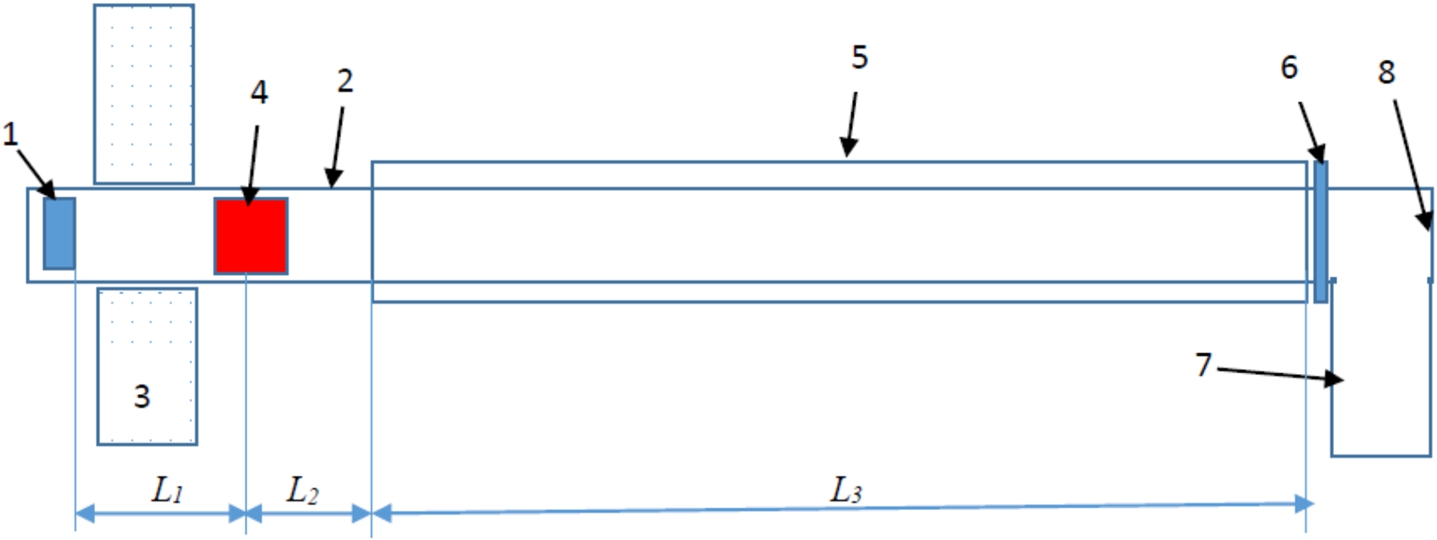
The specular neutron guide consists of a segment “1” of length
The accumulation volume (pos. 7) is located at the end of the guide. If one lets the UCN bunch enter the last small segment of the guide and the accumulation volume and then quickly closes it inside with the valve (pos. 6), the bunch is trapped. The UCN valve is opened only for the moment of arrival of the UCN bunches. It can be magnetic or mechanical, but transparent to VNCs to allow other downstream instruments to use them.
The main processes used in this method have been considered, some of them have already been implemented. For a pulsed source, this method can provide UCN densities approaching half of the peak phase-space density in the converter, as was proposed by F.L. Shapiro [45]. The choice of optimal phase-space range and the efficient extraction of VCNs are the basis of the “Steyerl turbine” [48]. Time focusing of neutrons was proposed in [14]. The motion of neutrons together with a material trap has been demonstrated [7,19]. The slowing down of neutrons by an inhomogeneous magnetic field has been repeatedly shown [38], and the slowing down of neutral atoms and molecules by an inhomogeneous magnetic field is used in experiments [11–13,21,25,50]. The novelty of the proposed concept lies in the combination of several methods developed in different fields of physics, so that the method of obtaining near-peak UCN densities can be implemented in practice.
3.Formation of UCN bunches
3.1.VCN converter
In the following, we show feasibility of the method on an example of a solid-deuterium converter by analogy with UCN converters [17]. It is placed into the maximum neutron flux in the vicinity of the neutron source and is surrounded by a nanodiamond reflector [27,36] in combination with a liquid-deuterium or hydrogen premoderator from all sides, except for the direction of the VCNs extraction. The purpose of the VCN converter is to increase the VCN phase-space density compared to that in the pre-moderator (the cold neutron source). The reflector is rather transparent for thermal and cold neutrons, but reflects efficiently VCNs. It is used to accumulate the VCN density in the converter and increase the fraction of VCNs directed along the guide axis. In the absence of the reflector, the converter size would have to be increased. Let the diameter of the converter disk be equal to the characteristic VCN guide diameter,
3.2.Neutron bunch
During a neutron source burst of duration
For matching the downstream devices, the intensity distribution within the bunch is important. For the solid-deuterium converter and both long and short source pulses, the phase-space density is fairly uniform in its central part
In the segment “1” of the specular neutron guide, the VCN bunch freely propagates and its length S increases in accordance with the formula known from the optics of beams:
3.3.Time focusing device
The focusing device can be considered as a “thin lens” – in which the neutron coordinates with respect to the center of the bunch change slightly, and the deviation of the velocity from the central value changes in the proportion to the distance to the center of the bunch. In the second drift segment, the bunch length decreases, and at a certain distance
The principle of operation of a magnetic lens is as follows. In a certain segment of the neutron guide, a magnetic field is produced that is uniform in space, but with its gradient directed along the neutron guide axis. When a neutron enters the magnetic field region, its kinetic energy changes by the value
An alternative focusing upon the interaction with a moving material wall (grating) is studied, for example, in a series of works [15,16], or with a neutron spin-flip in the intense magnetic field [6,20]. Other methods of focusing can also be proposed, for example, using the reflection of VCNs from a moving wall.
3.4.VCN decelerator
The resulting VCN bunch must be quickly trapped non-adiabatically into a magnetic or material trap and adiabatically decelerated together with the trap. The fast trapping is important for decreasing losses in the phase-space density and an adiabatic deceleration of the trap does not affect the phase-space density. By the time the bunch reaches the beginning of the deceleration segment, a neutron-reflecting “wall” has already been formed and it moves with a velocity
The material trap can be imagined in the form of an empty cola can without a lid on the side of the converter. Alternatively, it is sufficient to have only a flat bottom and the walls of the VCN specular guide would play the role of side walls of the trap. Note that an immobile material trap could only hold UCNs. To trap VCNs, one needs to move it with the bunch velocity and slow it down (for example, using a magnetic drive).
The principle of the magnetic wall is similar. It is not possible to provide a constant magnetic field strength high enough to decelerate VCNs. However, the use of a runaway magnetic wall, firstly, reduces the required field many times, and secondly, allows using a significantly larger pulsed magnetic field [23]. These gain factors are illustrated in Fig. 2 and explained below. The trap field is produced by a sequence of annular segments with length
Moving a light material wall with a magnetic drive is not energy-intensive, but building a reliable mechanical system with a large number of rapidly moving parts is a difficult task. In the case of a magnetic trap, it is easier to build a system that works reliably for a long time, however, it is energy intensive and more expensive to operate. Note that the simultaneous use of material and magnetic traps can significantly reduce the requirements for the magnetic system. On the other hand, it could significantly increase the deceleration rate or/and increase the range of longitudinal velocities of trapped neutrons.
The dynamics of neutron motion during deceleration is easier to describe in the case of a material trap, the wall of which is “infinitely sharp”. In this case, the boundaries of the region of stable motion are determined analytically. A neutron striking the wall at a velocity of
Fig. 2.
Effective potential that traps the neutron bunch in the reference system associated with the runaway decelerating trap.
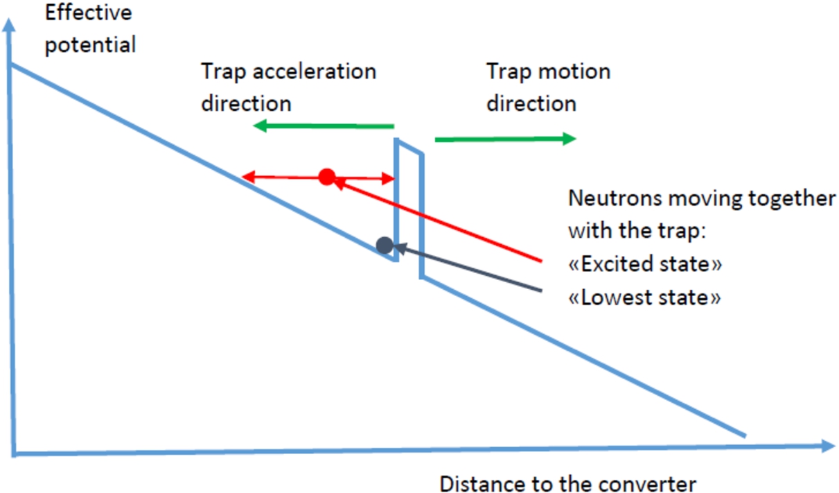
From the analysis of Fig. 2, two important conclusions can be drawn. With a sufficiently long neutron guide: 1) a running away and decelerating trap can, in principle, decelerate neutrons of any initial velocity, 2) the trap height can be arbitrary lower than the initial VCN energy; it is determined only by the energy range of the trapped UCNs.
4.Accumulation of UCN bunches from different pulses of the pulsed neutron source
With the parameters of our numerical example, the neutron bunch length is
Let new portions of neutrons
In the case of a magnetic trap used for slowing down neutrons, the UCN density could be doubled by adding bunches of neutrons with opposite spin orientations in one volume in analogy to the process of adding cold neutrons in one volume considered in [52]. This does not contradict Liouville’s theorem but has not yet been implemented with UCNs. The method of magnetized foils [41] could be used in principle to do this by adiabatically displacing UCNs of one polarization without affecting the UCNs with the other polarization. More details are given in Appendix A. Note that in the case of a material trap, both neutron polarizations are trapped simultaneously and adding bunches of neutrons with opposite spin orientations in one volume is not needed.
5.Parameters of the installation
The total guide length required to implement this method is about
Table 1
The parameters of the UCN source are given only for the purpose of demonstrating its feasibility and should be optimized for each specific project involving precise parameters of the neutron source, precise technical arrangement of the proposed focusing/decelerating system, and the optimization of the two simultaneously. In particular, several parameters can be changed to facilitate the practical implementation of the proposed method, which, however, will lead to a decrease in performance of the UCN source. These parameters include: the magnitude of the magnetic field strength of the trap, the diameter of the neutron guide, and the fraction of neutron source pulses used. This analysis goes far beyond the scope of this conference contribution. Note that the considered parameters are close to those of the ESS spallation source (
| Source pulse duration, | ms | 2 |
| Converter thickness (solid ortho-deuterium), | m | 0.1 |
| Converter diameter, d | m | 0.07 |
| Initial velocity of the bunch, VS0 | m/s | 50 |
| Length of the neutron bunch at the converter, | m | 0.1 |
| Maximum velocity spread in the bunch, | m/s | ±6 |
| Deceleration, a | m/s2 | 102 |
| Frequency of bunches, | Hz | 10 |
| Initial/final distance between bunches | m | 5/0.5 |
| Number of bunches in the deceleration segment | 6–7 | |
| Magnetic field strength in the deceleration segment | T | 4.3 |
| Length of the deceleration segment, | m | 12.5 |
| Total length of the neutron guide, L | m | 25 |
| Time of flight of the bunch through the guide, T | s | 0.67 |
| UCN bunch volume, | dm3 | 0.36 |
| Number of accumulated bunches | 700 |
6.Additional possibilities of the method
One can use a broader initial VCN spectrum employing a stronger magnetic field of the decelerating trap. This increases the bunch size, the number and volume of accumulated UCNs. After trapping such a broad neutron spectrum, the trap size increases adiabatically, its volume increases, and the velocities decrease in order to get the standard UCN spectrum. Note, however, that increasing the strength of magnetic fields can be associated with significant technical difficulties.
An alternative option is to convert UCNs (for instance, produced in a standing alone inexpensive UCN source of high phase-space density) to monochromatic VCNs or even cold neutrons by their acceleration in the analogous trap. The feasibility of building such a UCN source is becoming a hot topic; the first published example we are aware of is [46]; a few more configurations are discussed. In the long term this method may become an alternative to the construction of expensive standard neutron sources. In principle, the UCN density in a standing-alone dedicated UCN source can be significantly larger than the equilibrium UCN densities in cold sources of the most powerful modern neutron sources. Provided the acceleration of UCNs is not associated with significant losses in the phase-space density, one could obtain cold neutron pulses with record densities/fluxes without the need to build an expensive thermal neutron source. Note, however, that high neutron velocities require either an increase in the length of the accelerating segment in proportion to the square of the velocity, or an increase in the rate of acceleration. Both of these methods are resource-intensive, so the maximum achievable velocity is determined by a reasonable velocity/cost trade-off. At the acceleration rate considered above of
The method of increasing the UCN velocity to produce faster neutrons has already been studied in [29]. In contrast, the method for increasing the UCN energy proposed in this work preserves the density in the phase-space and can be considered as a logical continuation of this idea. Note that an increase in the velocity of all neutrons from some phase-space element and an increase in the energy of all neutrons from that element lead to different transformations in the phase-space. If an increase in velocity leads to an increase in the size of the bunch in space and, accordingly, to a decrease in the density in the phase-space (proportional to the ratio of the velocities), the method proposed here preserves the density in the phase-space.
7.Conclusion
We propose the method for producing UCNs based on the VCN deceleration by a decelerating trap. A high conversion efficiency of VCNs into UCNs can be achieved.
For pulsed neutron sources, the UCN density in the phase-space can approach the initial peak density (the idea of F.L. Shapiro); the maximum gain factor in the UCN density compared to the (otherwise used) mean UCN density is equal to the reciprocal duty cycle of the neutron source. Long pulses (as, for instance, at ESS) provide a simpler implementation due to larger neutron bunches and slower manipulations with them. On the other hand, short pulses (as, for example at IBR2 and projected IBR3) might provide a larger gain provided the efficient manipulation with short UCN pulses. Accumulation of different UCN bunches produced from different pulses of the neutron source allows to increase the total volume, which can be filled in with UCNs with this density by a factor of ∼103 compared to the single bunch volume; this gain factor can nearly approach the UCN storage time divided by the frequency of the pulsed neutron source.
The proposed method is also of interest for continuous neutron sources, in particular, for the PF2 facility [49] at ILL, due to the most efficient conversion of VCNs into UCNs. The neutron phase-space density, even in the existing liquid-deuterium source of cold neutrons [2] (>103 UCN/cm3), is an order of magnitude higher than the best worldwide achieved today. The use of an optimized (solid-deuterium) converter and an efficient (nanodiamond) VCN reflector would significantly increase this estimation. A loss-free extraction and deceleration of VCNs would provide an UCN source with a much higher performance than it is currently.
By analogy with the proposed VCN deceleration method, an accelerating trap converts UCNs to faster neutrons of an arbitrary velocity while preserving the initial high phase-space density produced in a standing alone inexpensive high-density UCN source.
Some of the methods for manipulating the elements of the phase-space occupied by neutrons have not yet been implemented; therefore, their analysis, modeling, implementation and optimization are important tasks that should be solved before starting any implementation of the proposed method as a whole. In particular, a prototype of the entire system can be built using a beam of hydrogen atoms with the same initial velocity: since their magnetic moment is three orders of magnitude higher, that is, the required magnetic field strengths are three orders of magnitude lower.
Acknowledgements
The authors are sincerely grateful to the whole UCN group at JINR for constructively discussing these ideas and participating in this development.
Appendices
Appendix A.
Appendix A.A possibility of increasing the density by adding UCNs with opposite polarizations
Some experiments, such as searching for a non-zero electric dipole moment of the neutron and spin-dependent extra fundamental interactions, spin-echo spectrometry, storing polarized neutrons in magnetic traps, studying the interaction of UCNs with magnetized surfaces, etc, use polarized neutrons. In this case, no additional transformation of the phase-space is required because the UCNs are already polarized.
Other types of experiments, such as measuring the lifetime of a neutron in material traps, studying the interaction of UCNs with a surface, neutron optics, using gravitational quantum states, (n,γ)-surface spectroscopy, etc, would benefit from doubling the UCN density due to the addition of UCNs with opposite polarizations in one volume, provided that the key parameter is the density, and not the total number of UCNs.
The Liouville theorem does not prohibit the addition of UCN densities with opposite polarization directions in one spatial volume. Neutron of the opposite polarizations occupy different phase-space volumes, corresponding to different polarizations. Indeed, the overlap of these volumes on one spatial coordinate does not result in the compression of the resulting phase-space volume as the total phase-space volume didn’t change. We illustrate this statement with the following example.
Imagine a volume separated by magnetized foils as shown in Fig. 3. Volume “1” is filled with UCNs of one polarization. Volume “2” is filled with UCNs of opposite polarization. The foils are magnetized in such a way that they transmit UCNs of one polarization, but block UCNs of the opposite polarization. If the arrows of UCN polarization and foil magnetization are parallel in Fig. 3, then the foil is transparent, and if they are antiparallel, then it is reflecting.
Fig. 3.
A simplified illustration of the principal possibility of doubling the UCN density by adding UCNs with opposite polarization directions in one volume. The storage volume is shown with thick blue line. Magnetized foils can slide along the inner walls, shown by red and green lines with arrows.
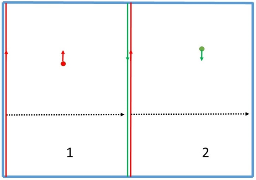
If we now adiabatically and simultaneously move the two foils to the right, as shown in Fig. 3, most of the UCNs will be in one half of the volume, and the density in it will almost double. At the initial moment of time, UCNs with “up” polarization (red circle with an arrow pointing up) fill volume “1”, and UCNs with “down” polarization (green circle with arrow pointing down) fill volume “2”. The foil indicated by green line with an arrow reflects UCNs with “down” polarization, but is transparent to UCNs with “up” polarization. The foils indicated by red lines with arrows reflect UCNs with “up” polarization, but are transparent to UCNs with “down” polarization. Now, adiabatically and parallel to each other, move the two red foils to the right, as shown by the black dotted arrows. UCNs from volume “1” move to volume “2”, and UCNs, which were in volume “2” initially, remain there.
This example is just an illustration of the principle possibility. Such a scheme for adding densities has never been implemented before, so its effectiveness is still difficult to assess. The main concern is the losses associated with the UCN absorption and up-scattering in the magnetized foils. To minimize this effect, one should carefully design the foils and decrease the number of subsequent penetration by optimizing the geometry of the traps and the foils. To ensure the adiabaticity condition, the number of UCN passages through the (green) magnetized foil must be “much greater than unity”, say 10. If its thickness is, say, 10 µm, the total UCN losses will be on the order of 20–30% percent of the UCN of one polarization, or 10–15% from the total density. Still there is a serious problem of designing the magnetic coating in such a way that magnetic potential compensates precisely nuclear potential (for the corresponding neutron polarization), so the method would not work for the fraction of slowest UCNs.
This method has never been discussed for neutrons, but has many well-known analogies in fields as diverse as electronics, chemistry, transmission of cell membranes, transmission of filters, and so on. A magnetized foil is a “semiconductor” for UCNs.
Appendix B.
Appendix B.A possibility of producing monochromatic neutrons with a high density in phase-space
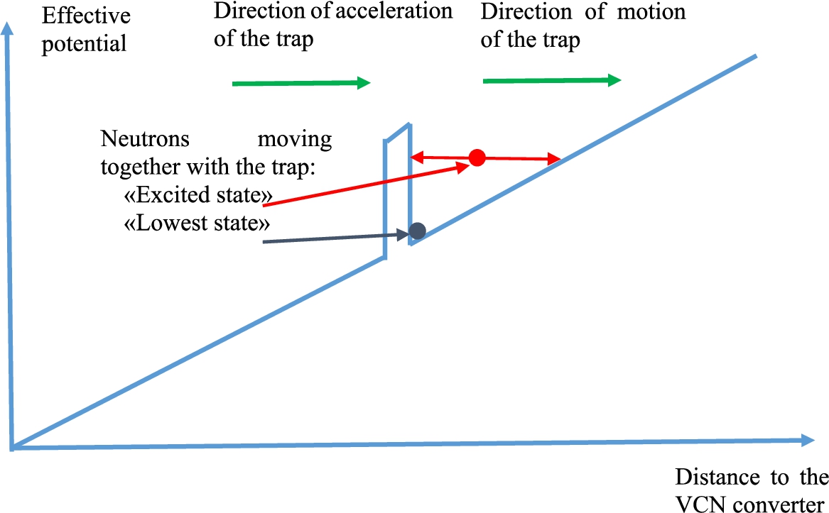
An obvious logical continuation of the VCN deceleration method is the reverse process of UCN acceleration by an oncoming accelerating trap, as shown in Fig. 4. The effective linear growing potential arises due to the acceleration of the coordinate system. A rectangular positive potential corresponds to a magnetic or material wall. For simplicity, edge effects, which are necessarily present in the case of a magnetic potential, are not indicated. A neutron with zero energy in a potential well shown as blue circle does not move relative to the well. A neutron with some energy relative to the potential well indicated by red circle oscillates in the potential well, as indicated by red arrows. For clarity, the height of the wall potential is disproportionally increased.
Fig. 4.
Effective potential locking the neutron bunch in the coordinate system associated with the running-away accelerating trap.
In principle, it is possible to obtain neutrons of any energy with the same high density in the phase-space as the initial UCN density in the phase-space. High velocities require either an increase in the length of the neutron guide in proportion to the square of the velocity, or an increase in the acceleration rate. Both of these methods are resource-intensive, so the maximum achievable velocity is determined by a reasonable velocity/cost trade-off. At the above acceleration rate of
References
[1] | C. Abel et al., Measurement of the permanent electric dipole moment of the neutron, Phys. Rev. Lett. 124: ((2020) ), 081803. doi:10.1103/PhysRevLett.124.081803. |
[2] | P. Ageron, Cold neutron sources, Nucl. Instr. Meth. A 284: ((1989) ), 197. doi:10.1016/0168-9002(89)90281-7. |
[3] | S. Ahmet et al., (TUCAN collaboration), first ultracold neutrons at TRIUMF, Phys. Rev. C 99: ((2019) ), 025503. doi:10.1103/PhysRevC.99.025503. |
[4] | A. Anghel et al., The PSI ultracold neutron source, Nucl. Instr. Meth. A 611: ((2009) ), 272. doi:10.1016/j.nima.2009.07.077. |
[5] | I. Antoniadis et al., Short-range fundamental forces, Compt. Rend. Phys. 12: ((2011) ), 755. doi:10.1016/j.crhy.2011.05.004. |
[6] | Y. Arimoto et al., Demonstration of focusing by a neutron accelerator, Phys. Rev. A 86: ((2012) ), 023843. doi:10.1103/PhysRevA.86.023843. |
[7] | B.V. Bagrjanov et al., Testing experimentally the dynamical convertor method for ultracold neutrons at a pulsed reactor BIGR, Phys. At. Nucl. 62: ((1999) ), 787. |
[8] | M. Baldo-Ceolin et al., A new experimental limit on neutron-antineutron oscillations, Zeit. Phys. C 63: ((1994) ), 409. doi:10.1007/BF01580321. |
[9] | G. Bison et al., Comparison of ultracold neutron sources for fundamental physics measurements, Phys. Rev. C 95: ((2017) ), 045503. doi:10.1103/PhysRevC.95.045503. |
[10] | S.M. Chernyavsky et al., Temperature dependence of the probability of “small heating” and total losses of UCNs on the surface of Fomblin oils of different molecular mass, Europ. Phys. J. C 79: ((2019) ), 329. doi:10.1140/epjc/s10052-019-6835-z. |
[11] | T. Cremers et al., Design and construction of a multistage Zeeman decelerator for crossed molecular beams scattering experiments, Rev. Sci. Instr. 90: ((2019) ), 013104. doi:10.1063/1.5066062. |
[12] | T. Damjanovic et al., A new design for a travelling-wave Zeeman decelerator: II, Theory, New J. Phys. 23: ((2021) ), 105006. doi:10.1088/1367-2630/ac2b52. |
[13] | T. Damjanovic et al., A new design for a travelling-wave Zeeman decelerator: II. Experiment, New J. Phys. 23: ((2021) ), 105007. doi:10.1088/1367-2630/ac2c2b. |
[14] | A.I. Frank et al., Time focusing of neutrons, Phys. At. Nucl. 63: ((2000) ), 545. doi:10.1134/1.855665. |
[15] | A.I. Frank et al., Non-stationary transformation of neutron energy by moving grating, J. Phys. Conf. Ser. 746: ((2016) ), 012053. doi:10.1088/1742-6596/746/1/012053. |
[16] | А.И. Франк, О возможности создания источника УХН на импульсном реакторе периодического действия, ЭЧАЯ 53: ((2022) ), 64. [A.I. Frank et al., On the possibility of creating a UCN source on a pulsed reactor, PEPAN 53 (2022) 64]. |
[17] | R. Golub et al., The interaction of ultracold neutrons (UCNs) with liquid helium and a superthermal UCN source, Phys. Lett. A 53: ((1975) ), 133. doi:10.1016/0375-9601(75)90500-9. |
[18] | K.B. Grammer et al., Measurement of the scattering cross section of slow neutrons on liquid parahydrogen from neutron transmission, Phys. Rev. B 91: ((2015) ), 180301. doi:10.1103/PhysRevB.91.180301. |
[19] | V.K. Ignatovich et al., Neutron transportation in a closed vessel, Phys. At. Nucl. 65: ((2002) ), 2029. |
[20] | S. Imajo et al., Ultracold neutron time focusing experiment and performance evaluation of an improved UCN rebuncher at J-PARC/MLF, JPS Conf. Proc. 33: ((2021) ), 01191. |
[21] | P. Jansen et al., Manipulating beams of paramagnetic atoms and molecules using inhomogeneous magnetic field, Progr. Nucl. Magn. Res. Spectr. 120: ((2020) ), 118. doi:10.1016/j.pnmrs.2020.08.002. |
[22] | T. Jenke et al., Gravity resonance spectroscopy constraint dark energy and dark matter scenarios, Phys. Rev. Lett. 112: ((2014) ), 151105. doi:10.1103/PhysRevLett.112.151105. |
[23] | P. Katitza, Some observations on α-particle tracks in a magnetic field, Proc. Cambridge Philos. Soc. A 109: ((1923) ), 511. |
[24] | B. Lauss, Ultracold neutron production at the second spallation target of the Paul Scherrer Institute, Phys. Proc. 51: ((2014) ), 98. doi:10.1016/j.phpro.2013.12.022. |
[25] | E. Lavert-Ofir et al., Stopping paramagnetic supersonic beams: The advantage of a co-moving magnetic trap decelerator, Phys. Chem. Chem. Phys. 13: ((2011) ), 18948. doi:10.1039/c1cp21225g. |
[26] | V.I. Luschikov et al., Observation of ultracold neutrons, JETP Lett. 9: ((1969) ), 23. |
[27] | E.V. Lychagin et al., Storage of very cold neutrons in a trap with nanostructured walls, Phys. Lett. B 679: ((2009) ), 186. doi:10.1016/j.physletb.2009.07.030. |
[28] | E.V. Lychagin et al., UCN sources at external beams of thermal neutrons. An example of PIK reactor, Nucl. Instr. Meth. A 83: ((2016) ), 47. doi:10.1016/j.nima.2016.04.008. |
[29] | S. Mayer et al., New aspects for high intensity neutron beam production, Nucl. Instr. Meth. A 608: ((2009) ), 434. doi:10.1016/j.nima.2009.07.030. |
[30] | {И.} Мешков, Индивидуальная инжекция, охлаждение и группировка редких радиоактивных ионов в накопительном кольце, Ат. Эн. 94: ((2003) ), 5. [I. Meshkov et al., Individual injection, cooling and grouping of rare radioactive ions in a storage ring, At. En. 94 (2003), 5]. |
[31] | F. Mezei et al., Low dimensional neutron moderators for enhanced sources brightness, J. Neutr. Res. 17: ((2014) ), 101. doi:10.3233/JNR-140013. |
[32] | V.V. Nesvizhevsky, Why very cold neutrons could be useful for neutron antineutron oscillation searches, J. Neutr. Res. (2022), submitted. |
[33] | V.V. Nesvizhevsky et al., Quantum states of neutrons in the Earth’s gravitational field, Nature 415: ((2002) ), 297. doi:10.1038/415297a. |
[34] | V.V. Nesvizhevsky et al., Neutron whispering gallery, Nature Phys. 6: ((2010) ), 114. doi:10.1038/nphys1478. |
[35] | V.V. Nesvizhevsky et al., The method of UCN “small heating” measurement in the big gravitational spectrometer (BGS) and studies of this effect on Fomblin oil H-VAC 18/8, Rev. Sci. Instr. 89: ((2018) ), 023501. doi:10.1063/1.5010974. |
[36] | V.V. Nesvizhevsky et al., Fluorinated nanodiamonds as unique neutron reflector, Carbon 130: ((2018) ), 299. |
[37] | V.V. Nesvizhevsky et al., Experimental approach to search for free neutron-antineutron oscillations based on coherent neutron and antineutron mirror reflection, Phys. Rev. Lett. 122: ((2019) ), 221802. doi:10.1103/PhysRevLett.122.221802. |
[38] | L. Niel et al., Acceleration, deceleration and monochromatization of neutrons in time dependent magnetic field, Zeit. Phys. B 74: ((1989) ), 133. doi:10.1007/BF01307246. |
[39] | R.W. Patie et al., Measurement of the neutron lifetime using a magneto-gravitational trap and in situ detection, Science 360: ((2018) ), 627. doi:10.1126/science.aan8895. |
[40] | A.P. Serebrov et al., Development of UCN sources at PNPI, J. Neutr. Res. ((2022) ). doi:10.3233/JNR-220007. |
[41] | Y.N. Pokotilovskii et al., Ferromagnetic gates for ultracold neutrons, Instr. Exp. Tech. 10: ((1976) ), 631. |
[42] | A. Saunders et al., Demonstration of a solid deuterium source of ultracold neutrons, Phys. Lett. B 593: ((2004) ), 55. doi:10.1016/j.physletb.2004.04.048. |
[43] | A.P. Serebrov et al., Neutron lifetime measurements using gravitationally trapped ultracold neutrons, Phys. Rev. C 78: ((2008) ), 035505. doi:10.1103/PhysRevC.78.035505. |
[44] | E. Chanel et al., Concept and strategy of SuperSUN: A new ultracold neutron converter, J. Neutr. Res. ((2022) ). doi:10.3233/JNR-220013. |
[45] | Ф.Л. Шапиро, Замечания к вопросам об измерении фаз структурных амплитуд в нейтронной дифракции и о накоплении нейтронов, ЭЧАЯ 4: ((1971) ), 973. [F.L. Shapiro, Remarks on measuring the phases of structural amplitudes in neutron diffraction and about neutron accumulation, PEPAN 4 (1971), 973]. |
[46] | Y.C. Shin et al., Compact ultracold neutron source for low-energy accelerator-driven sources, Europ. Phys. J. 136: ((2021) ), 136. |
[47] | A. Steyerl, Measurements of total cross sections for very slow neutrons with velocities from 100-m/sec to 5 m/sec, Phys. Lett. B 29: ((1969) ), 33. doi:10.1016/0370-2693(69)90127-0. |
[48] | A. Steyerl, Neutron turbine as an efficient source of ultracold neutrons, Nucl. Instr. Meth. A 125: ((1975) ), 461. doi:10.1016/0029-554X(75)90265-7. |
[49] | A. Steyerl et al., A new source of cold and ultracold neutrons, Phys. Lett. A 116: ((1986) ), 347. doi:10.1016/0375-9601(86)90587-6. |
[50] | N. Vanhaecke et al., Multistage Zeeman deceleration of hydrogen atoms, Phys. Rev. A 75: ((2007) ), 031402. doi:10.1103/PhysRevA.75.031402. |
[51] | A.T. Yue et al., Improved determination of the neutron lifetime, Phys. Rev. Lett. 111: ((2013) ), 22501. doi:10.1103/PhysRevLett.111.022501. |
[52] | D. Martin Rodriguez et al., How to polarise all neutrons in one beam: a high performance polariser and neutron transport system, J. Phys.: Conf. Ser. 746: ((2016) ) 012015. doi:10.1088/1742-6596/746/1/012015. |


