
Automatic beam stop changer device
Abstract
Small Angle Scattering techniques are now commonly used worldwide by scientists to characterize their samples. Collimator slit size opening is one among many parameters that the user can fine tune to fit his experiment in terms of the balance between intensity, resolution and transmitted beam size on the detector. Although every instrument in the world offer this possibility, surprisingly very few offer the possibility to change the beam stop size, located in front of the detector, to match with transmitted beam size. This article describes a device allowing changing beam stops remotely and reliably during an experiment, and its integration into an existing instrument.
1.Introduction
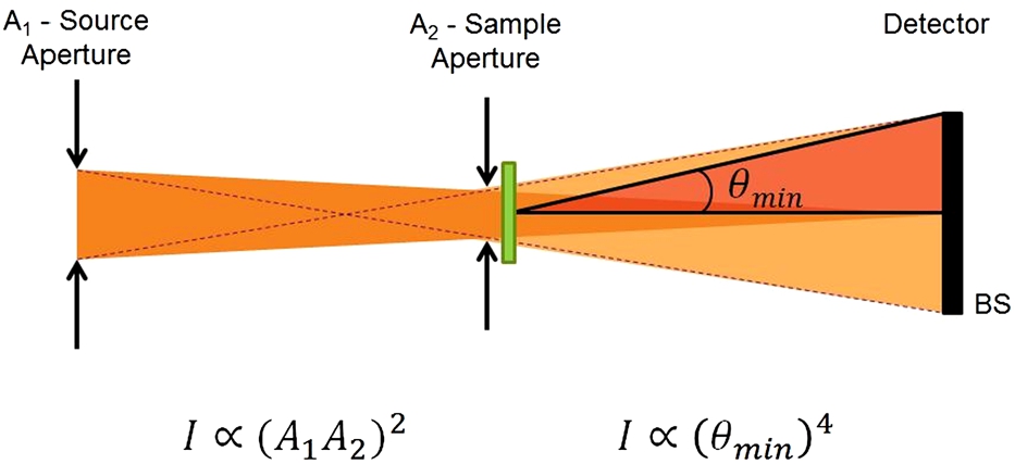
Small Angle Scattering (SAS) techniques are world widely used for sample characterization and can be used with several probing sources such as neutrons (SANS) [4], X-rays (SAXS) [5] and light (SALS) [10], and can deliver information about density or size distribution of particles, shape or interface effects and magnetic structures [9] in the range of 1–1000 nm typically of interest for soft matter (polymers, electrolytes, micelles, vesicles, biological systems like proteins) [3], materials science (chemical demixing, precipitates, porous materials, alloys in metallurgy) [8] and magnetic materials (critical magnetic fluctuations near transitions, magnetic particles or ferro-fluids [12], vortices in superconductors, nano-magnets, long-range helicoïdal orders). Typical SAS instruments offer the user a variety of collimation slit dimensions in order to tailor the probing beam according to the balance to get a good wave vector resolution with a tiny beam at the expense of intensity hence counting time necessary to achieve good statistics [7]. Figure 1 represents a schematic collimation. If
Fig. 1.
Sketch of SAS collimation and parameters.
This paper describes the design and integration of an automatic beam stop changer device developed for the SANS instrument, PA20 [2] on production since 2015 at LLB on the Orphée reactor located at CEA, France. This SANS instrument also offers Grazing Incidence (GISANS) possibility. This means that the beam can be tailored along a thin horizontal or vertical beam onto the sample to produce an equivalent thin horizontal or vertical transmitted beam on the detector. The first part of the paper will establish the implementation constraints due to the instrument environment, then the second part will present the design of the device and the last part will describe its integration on PA20.
2.Implementation constraints
2.1.Compatibility with a 25 × 25 mm 2
One of the purpose of PA20 is to be able to reach as small scattering wave vectors as possible. The pixel size of the rear detector is 5 mm so it was decided to design the beam stop to measure scattering wave vectors smaller than
2.2.No heat production
Detector tanks used for SANS are vacuumized in order to prevent beam attenuation due to the scattering of the neutron by the nitrogen content in air. Therefore, any device located inside the detector tank must not produce any heat, otherwise it must be cooled. According to Section 2.1 the beam stop has to be a compact device and is not compatible with fitting a cooling system hence it must not produce any heat.
2.3.Reliable positioning
Changing beam stops among a collection requires reliable positioning both in front of the detector and on its rack. Reliable positioning in front of the detector is crucial in order to efficiently absorb the direct beam. Also beam stops may have various shapes, from square for SANS to rectangle for GISANS, thus they must also be reliably oriented with their edges parallel to the detector pixels. Reliable positioning of the beam stop on its parking location is also important so as to have a reliable system, able to cycle without need to access the detector vessel for maintenance in case it falls or gets stuck. Indeed, any human intervention inside the detector vessel is time consuming and translates to a couple of hours: first get the vessel back to atmospheric pressure, then fix the beam stop and finally pump the vessel to the required pressure, which wastes time for the experiment.
2.4.Transparent to neutron
The beam stop must be held and fixed onto XY translation axes for its accurate positioning. Also it is not recommended to have a shadow of the beam stop holder on the detector. Aluminum 5754 is a suitable and commonly used material for the holder as it has weak interaction with neutron hence it is almost transparent up to a thickness of a few millimetres.
2.5.Beam stop weight
Table 1 lists the beam stops foreseen for PA20. These beam stops are made out of 5 mm of boron carbide glued on an Aluminum plate of 2 mm thickness producing a beam attenuation of
Table 1
Beam stops to be used on PA20
| ID | 1 | 2 | 3 | 4 | 5 | 6 | 7 | 8 |
| Width (mm) | 50 | 37 | 25 | 50 | 37 | 25 | 50 | 50 |
| Height (mm) | 50 | 37 | 25 | 37 | 100 | 100 | 100 | 25 |
2.6.Automated
For the same reason as cited in Section 2.3, human intervention inside the detector tank is not compatible with a high rate of measurements so the device must be automated, ideally via the instrument control software.
2.7.Independance of electric power
The device cannot be dependent on electric power. In other words, it must not fall or loose position in case of electrical shut down otherwise it would not fulfil the reliability requirement of Section 2.3.
3.Device
The model PEM 2020 holding magnet from Binder Magnetic was chosen in order to fulfil all the constraints listed in Section 2. It consists of a 20 mm diameter electromagnet with a permanent magnet inside. The advantage of such a magnetic system is the following: when no voltage is applied to the electromagnet, or in case of electric shut down, the magnetic field of the permanent magnet holds the beam stop. On the other hand, when a voltage of 24 V is applied to the electromagnet then the magnetic field of the permanent magnet is compensated and the device releases the beam stop. This procedure applies only when a change of beam stop is required, thus only for a few seconds so the heating is negligible and fulfils the heating requirement (Section 2.2). Figure 2 presents the magnetic force of the device for a Fe base plate of 2.5 mm thickness as a function of the air gap. Without air gap, the magnetic force is 60 N and an air gap, or waviness, up to 250 μm still allow to hold the heaviest beam stop with a safety factor of 3.
Fig. 2.
Magnetic force of the PEM 2020 electromagnet as a function of the air gap for an Fe base plate of 2.5 mm.

Concerning the reliability of the beam stop positioning on the holder, Fig. 3 presents a side picture of the electromagnet holding the beam stop fixed on its magnetic L-shape interface. The circle emphasizes that the electromagnet has been machined one indent on both side in order to match the edges also located on both sides of the beam stop interface. Therefore, the indent/edge ensemble insures that the beam stop will reliably magnetically stick to the electromagnet.
Fig. 3.
Picture of a beam stop held by the device. The circle emphasizes the indent machined on the electromagnet matching the edge of the beam stop interface for self-alignment.
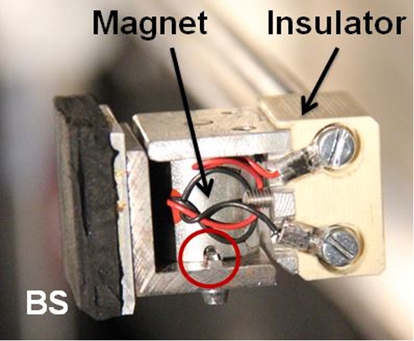
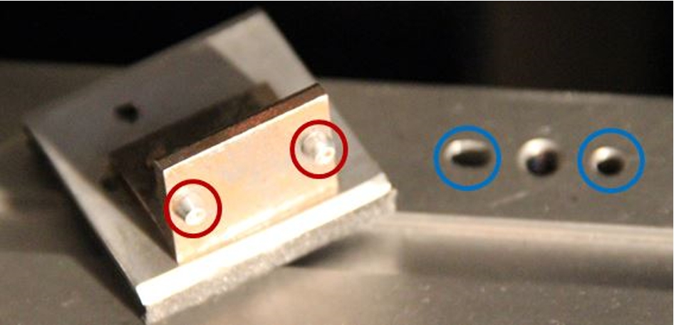
Figure 4 presents the system for a reliable positioning of the beam stop on its parking location. The beam stop interface plate has two conical parts designed to smoothly fit the circular/elongated holes in the parking position. Since the conical parts must be hidden by the beam stop, the parking has been further machined according to the height of the conical part so that the beam stop lays at the same time inside the holes and on the beam stop side.
Fig. 4.
Picture of the bottom of the beam stop interface plate with its two conical parts designed to fit the circular/elongated holes in the parking position. Since the conical parts must be hidden by the beam stop, the parking has been machined so that the beam stop lays at the same time inside the holes with its conical parts and on the beam stop bottom side.
In order to have a transparent device, the voltage is applied to the electromagnet through its conducting Aluminum holder, hence no cable is needed in front of the detector. For this purpose, two hollow rods of Aluminum have been chosen as device holder. Figure 3 shows the side of the device where the two cables of the electromagnet are hidden behind the beam stop and connected to each Aluminum rod through an insulator. Also Fig. 5 shows that the whole device is hidden behind a beam stop of
Fig. 5.
Picture of the device fully hidden behind the smallest beam stop size of
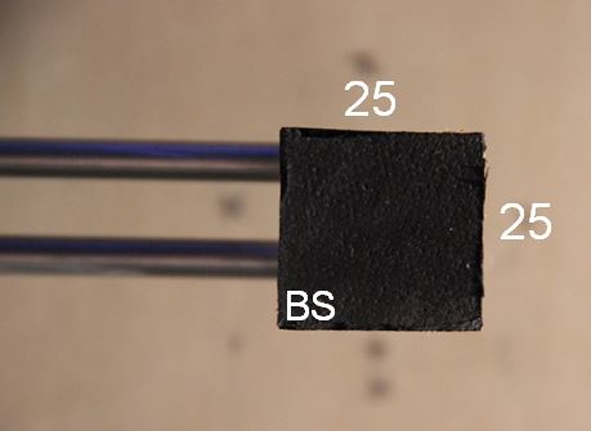
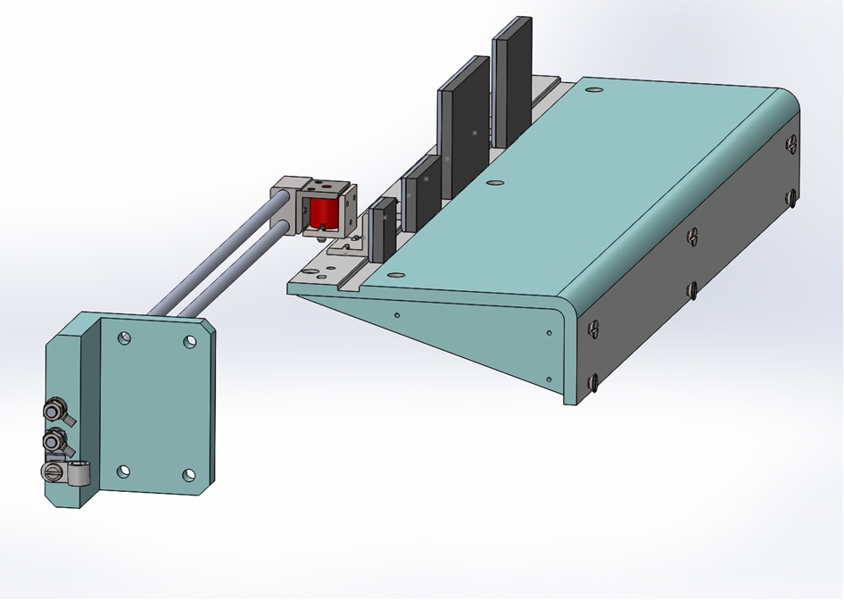
Fig. 6.
CAD side view of the beam stop device.
4.Integration
4.1.Mechanical
The integration of the device on PA20 is fairly straight forward since the 2 axes translation of the beam stop can be used both to adjust the beam stop position and exchange beam stops at the parking location. This translation system is composed by 2 linear toothed belt translations with a course of 700 mm (Rollon) powered by a cc moto-reductor (Maxon) coded by an absolute encoder (Baumer) and with magnetic end-switches (Cherry). Figure 6 is a CAD side view of the device. Obviously the parking location needs to be located outside of the sensitive surface of the detector as shown on Fig. 7. In the case of PA20, it is located at the bottom right corner of the detector. The XY course of the translations are already adapted to access these positions because they are designed to position the beam stop up to 60 cm with respect to the beam axis in GISANS mode. Two electric cables have been mounted onto the XY translation system of the beam stop in order to apply the voltage to the electromagnet through the Aluminum holder. The typical required time to exchange 2 beam stops is 10–15 s. It corresponds to the following actions: moving the holder with the actual beam stop to its parking location, releasing the beams stop by applying the voltage on the electromagnet, moving the holder to the requested beam stop parking location, releasing the voltage on the electromagnet to stick the beam stop and moving it in the beam axis.
4.2.Control software
The XY axes of the beam stop were already configured in the instrument control software, so only the calibration of the X and Y locations of the 8 beam stop had to be added as well as the procedure for beam stop change. When a change of beam stop is requested, first the actual beam stop is driven to its parking location and the voltage is applied for its release. Then the beam stop device is driven to the requested beam stop location and the voltage is cut to stick the beam stop on the device. Finally, the new beam stop is driven to the requested position.
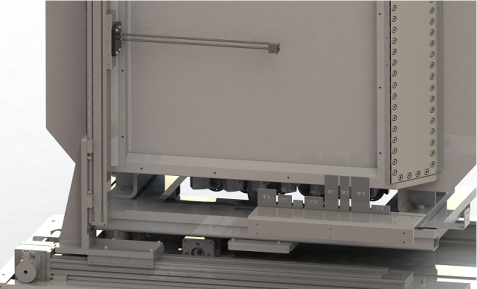
Fig. 7.
CAD of the beam stop device with respect to the detector, and the beamstop parking area located outside of the detector sensitive area. The dimensions of the beam stops are according to Table 1.
5.Discussion
A simple and effective beam stop changer device and its implementation on a SANS instrument have been presented. The aim of the device is to provide the instrument with a set of beam stops permitting optimization of the smaller scattering wave vector with respect to the collimation configuration, and it can be integrated in almost any instrument with minimal impact. The principle of using an electromagnet hosting a permanent magnet can be extended to other areas, for instance for sample changers. It could also find other applications among SAS instrument, still in front of the detector, such as the positioning of various attenuators for transmission measurements or even the positioning of a sCMOS [11] camera, with very small pixels when Very Small Angle Neutron Scattering (VSANS) information is required.
Acknowledgements
The authors would like to thank the instrument scientists, A. Brûlet and G. Chaboussant, for their support and definition of the required beam stop sizes, the electronicians, F. Coneggo, W. Josse and P. Lambert for the cabling and tests and E. Jorgji for the integration in the control software.
References
[1] | N.F. Berk and K.A. Hardman-Rhyne, J. Appl. Cryst 21: ((1988) ), 645–651. doi:10.1107/S0021889888004054. |
[2] | G. Chaboussant, S. Désert, P. Lavie and A. Brûlet, J. Phys: Conf. Ser. ((2012) ), 340, 012002. |
[3] | F. Cousin, J. Gummel, D. Ung et al., Langmuir 21: ((2005) ), 9675–9688. doi:10.1021/la0510174. |
[4] | O. Glatter and O. Kratky, Small Angle X-Ray Scattering, Academic, New York, (1982) . |
[5] | A. Guinier and G. Fournet, Small Angle Scattering of X-Rays, John Wiley & Sons, New York, (1955) . |
[6] | B. Lyot, L’Astronomie 45: ((1931) ), p. 248. |
[7] | F.M.A. Margaça, A.N. Falcao, J.F. Salgado and F.G. Carvalho, J. Appl. Cryst 24: ((1991) ), 994–998. doi:10.1107/S0021889891006672. |
[8] | Y.B. Melnichenko and G.D. Wignall, J. Appl. Phys. ((2007) ), 102, 021101. |
[9] | A. Michels and J. Weissmuller, Rep. Prog. Phys 71: ((2008) ), 066501. doi:10.1088/0034-4885/71/6/066501. |
[10] | A. Thill, S. Désert and M. Delsanti, Eur. Phys. J. AP 17: ((2002) ), 201–208. doi:10.1051/epjap:2002013. |
[11] | P. Trtik, J. Hovind, C. Grünzweig, A. Bollhalder, V. Thominet, C. David, A. Kaestner and H. Lehmann, Phys. Procedia 69: ((2015) ), 169–176. doi:10.1016/j.phpro.2015.07.024. |
[12] | A. Wiedenmann, U. Keiderling, R.P. May and C. Dewhurst, Physica B ((2006) ), 385–386, 453456. |


