
Integration of scanning and image processing algorithms for lane detection based on fuzzy method
Abstract
In order to detect lane rapidly and accurately, the integration of scanning and image processing algorithms (SIP) based on the fuzzy method is proposed. Further, combination of the proposed algorithm with an adaptive threshold value for image binarization, the least-square method and Bessel curve algorithm are proposed for detection and to fit the lane. The proposed SIP algorithm was evaluated by various tests. The experimental results indicate that the average time consumed for the detection of lane in each frame is 16.7639 ms, and the accuracy of lane detection is 95% . The proposed algorithm demonstrates good robustness, and can be used as the core algorithm for further application in lane departure warning systems.
1Introduction
Within the last few years, statistics have indicated that traffic accidents are fa major concern around the world, and that single-vehicle road departure crashes lead to more fatalities than any other type of crash [14, 16]. Several technical solutions have been proposed, e.g., lane departure warning (LDW) systems to use computer vision and highly-specialized algorithms to detect lane markings, which would then generate a warning to the driver [12]. An unintentional lane-departure is typically due to the involuntary fade of the driver’s vision caused by use of a mobile phone, falling asleep [10], chatting, or other distractions [3]. Extraction of lane-related information is the first step in lane-departure detection. Detecting road markings is also a formidable problem. Computer vision approaches [5] can be used to perform lane edge detection, and provide a measure of distance between the vehicle and the lane edge [7, 19]. Roads can be marked by well-defined solid-line markings [18], segmented-line markings [6], circular-reflector markings, or other methods [4]. Most paved roads in China have lane marks painted in white. However, road surface environmental conditions such as glare and snow, unpredictable weather conditions and time of day, may inhibit widespread adoption.
Pilutti and Ulsoy [15] proposed a system identification approach by applying an ARX model to estimate the relationship between vehicle lateral position and the steering wheel angular position. Lee [9] proposed a feature-based lane-departure detection system using edge information to define an edge distribution function (EDF). Kwon and Lee [17] developed a lane departure warning system utilizing heuristic decision-making strategies, a time-to-lane crossing (TLC) strategy and a lateral offset (LO) strategy to improve decision-making performance. Hsiao, et al. [11] proposed an improved lane detection algorithm based on peak finding using a spatiotemporal mechanism to detect lane boundaries and then generate warning signals. Wang, Lin, and Chen [8] developed a vision-based lane detection and departure warning system which combines fuzzy rules, the fuzzy C-mean and the self-clustering algorithm (SCA) to process spatial information, and Canny algorithms to enhance lane boundary information to suit various light conditions throughout the day. López, Serrat, and Cañero [1] proposed a generic robust estimation method based on ridge orientation to extract lane features. Jiang, et al. [13] proposed a new weak lane model based on particle filtration to detect all types of lanes. Wu, Lin, and Lee [2] proposed a special-purpose lane-detection method based on a functional neurofuzzy network, used the fan-scanning-detection method to extract lane boundary information.
Almost all LDW systems follow a similar flow. First, a road model and vehicle model are proposed. Second, a sensing system is used to gather data information regarding the traveling environment of the vehicle. Third, data from the sensors are fused to estimate lane position. Finally, the vehicle model can be used to refine the estimates and determine whether to issue a warning. This paper proposes a framework for the development of a lane-detection algorithm, focused on a computer vision method combined with lane data to extract features. Features information such as edges and textures are used in combination with the road model to detect the lane position.
Much of the information about the road captured by camera when a vehicle is driving is useless to lane detection. As a result, this paper proposes an algorithm which combines the scanning area algorithm to obtaining points and the image processing algorithm to detect the lane. The algorithm obtains the efficient points of the lane line in the scanning area which the lane lays, so that the computing time of the algorithm can be greatly reduced. This paper is organized as follows. In Section 2, a lane detection algorithm is proposed, including the image binarization algorithm which can self-adaptively obtain a threshold value, the image processing algorithm which can obtain the intersection of the lane and the image edge, and the scanning algorithm. Additionally, it introduces the algorithm selection with the application of a fuzzy controller, as well as the lane fitting method. In Section 3, the experimental results and comparative studies are provided. Finally, conclusions are discussed in Section 4.
2Lane detection
Image preprocessing is a key component to lane detection, which can greatly increase system performance. Road modeling depends on the road environment. A video camera used to identify the lane can be installed at the top right of the windscreen. The adjustment principle of the camera overlooking angle is to ensure that the horizontal middle line of the camera screen meets the vanishing line of the road far in the distance. Figure 1 shows the lane detection process used in the proposed algorithm.
2.1Adaptive image binarization threshold algorithm
For the lane detection algorithm based on computer vision, the accuracy of the lane detection is affected by changes in weather and light intensity on the road surface. To improve the real-time performance of lane detection, binarization processing is conducted on the RGB image captured by the camera. The binarization threshold of the image must therefore be rapidly and accurately determined. For this reason, this paper proposes an adaptive image binarization threshold algorithm, as follows:
Adaptive Image Binarization Threshold Algorithm
Step 1: n = 1;//To initiate the binarization threshold value.
i = 255;//To initiate the controlling variable of the loop.
Step 2: For i > = 0 do;//To determine the last coordinates of the fastest falling point.
if Array[i] > 500 then;//Storage of binarization threshold. break; endif;
i = i-1;//endfor.
Step 3: n = i+10;//Access to the fastest falling point coordinate values, then read its 10th points’ value in the array.
Step 4: for Array[n] > 50 and n < 255 do;//To obtain the correct binarization threshold.
n = n+5; end.
Effects are induced by scenery changes ahead of the vehicle, including: clouds, houses beside the road, trees, road signs, etc. The proposed algorithm is based on statistical information to adaptively obtain the image binarization threshold.
2.2Obtain the intersection of lane and image edge
Ideally, after binarization, the lane will extend to the bottom of the image or to the margin of the broadside image. A lane depicted by a dotted line is shown in Fig. 2, in which the green portion depicts the edge area of the image.
Because the image captured by the camera represents a certain range of road environment, conditions will not be acceptable when three lane lines simultaneously intersect with the bottom edge of the image. If the four lane lines closest to the vehicle are all dotted lines, then some lanes will intersect with the image bottom, while some lanes will intersect with the image side. An algorithm is proposed to determine the intersection between the lane and the image side by scanning, expressed as follows:
Obtain the Intersection of Lane and the Image Edge Algorithm
Step 1: //On the lower part of the image block processing, as shown in Fig. 3, the b 2 block pattern is used to count all pixels for the binary b 2 block, with b representing the length of the block.
In the block, if N point w ⩾ N point b , k = 1, else k = 0 (N point w is the number of the white points, and N point b is the number of black points). Due to the fact that the edge of the green area is only at the image edge, the number of the blocks processed by the algorithm is shown in Equation (1):
(1)
Step 2:// Scan image edges.
Step 2.1. i = 0;
Step 2.2. Scan image bottom from left to right, i = i+1 when meeting Point w , then retreat to the state of the white line area.
Step 2.3. i = i-1/ When black spots (Point b ) is met, the points should be saved. If δ ≤ 5 and the distance from the identified points in the previous frame is less than 5 (d≤5), repeat Step 2.2 until all the edge points on the image edge have been scanned.
Step 3:// Scan the left side of the sidebar from the bottom up.
Step 3.1. Check k = 1. In the left points in the sidebar at the bottom of the image, if k = 1, then move up five pixels, which illustrates that these points may overlap.
Step 3.2. Reaches an end if a white point is obtained in the left sidebar in the image.
Step 4:// Scan right sidebar from the bottom up.
Step 4.1. Check k = 1. In the right points, which are at the bottom sidebar of the image, if k = 1, then move up five pixels, which illustrates that these points may overlap.
Step 4.2. Reaches an end if a white point is obtained in the right sidebar of the image.
With the application of this algorithm, the intersections of the lane and the image edge can be obtained. However, when there is a strong light on the road, the result of image binarization will be inaccurate. When the lane is denoted by a dotted line, all intersections of the lane and the image edge cannot be determined. One node, at least, can be obtained with this algorithm; some nodes can be obtained in most cases. For this reason, based on the above algorithm to get the intersection of the lane and the image side by scanning, this paper further proposes an algorithm to obtain lost intersections, described as follows.
Obtaining Lost Intersections Algorithm
Step 1: Obtain two nodes, Point G and Point H , intersections of the lane and the image edge, by the scanning algorithm, as shown in Fig. 4.
Step 2: Line _ BC : turn 90 degrees counterclockwise to cobtain Line _ AC ; turn Line _ DE 90 degrees clockwise to obtain Line _ DF .
Step 3: As the greatest width of the lane in the image is 5/7 of the image (the area between Point I and Point J in Fig. 4), the vanishing point P K of the default lane is described as follow:
The horizontal coordinate is expressed in Equation (2):
(2)
The vertical coordinate is expressed in Equation (3):
(3)
Step 4: Calculate the coordinates of Point M according to the position of Point K and Point H . When Point H is mapped to Line _ D F, the lane slope r is obtained based on the coordinate of Point H . Then, the coordinate of Point M can be calculated.
Step 5: Repeat Steps 1 through 4 to calculate the coordinates of ‘Point L , Point I , Point J , Point M ’.
According to the scanning algorithm, the position of ‘Point L , Point I , Point J , Point M ’ will be easily obtained by the further application of the algorithm to obtain lost nodes as long as any two nodes of ‘Point G , Point I , Point J , Point H ’ have been obtained. In the driving process, the position of ‘Point L , Point I , Point J , Point M ’ will shift left or right with vehicle movement. Once the positions of ‘Point L , Point I , Point J , Point M ’ are obtained, they can be used to calculate all intersections of lane and image edge in the next frame.
Based on the above analysis, this algorithm can be applied to calculate all intersections on the condition that some intersections of the lane and image edge were not detected as shown in Fig. 5.
In Fig. 5(a) and (b), the blue area between the two lines is the scanning area of the left lane, the light blue area between the two lines is the scanning area of right lane, the black circle is the lane points found in the scanning area, and the red circle is the points calculated by the locations of other points. In Fig. 5(a), the white circle represents the nodes between a lane of the current frame and the bottom edge of the image calculated according to the lane position in the past frame. In Fig. 5(b), the pink points represent the nodes between the lane and left edge of the image.
2.3Fuzzy controller
This paper uses the fuzzy method to determine whether to choose the intersection algorithm by scanning area or the intersection algorithm during image processing. ‘IF X AND Y THEN Z’ fuzzy rules were used to construct a rule-based fuzzy system [2, 8]. As the image is being processed by the algorithm looking for intersections between the lane and image edge and the algorithm to obtain lost nodes, the algorithm can obtain both coordinates of ‘Point L , Point I , Point J , Point M ’ (the nodes of the lane and the image edge) and the coordinates of the lane vanishing point. In this study, the moving distance of intersection of lanes and the images was divided into three member functions by the algorithm, as follows:
The fuzzy controller uses the Centroid-method to defuzzify the output variable without losing all the information of fuzzy rules. The Centroid-method is described by Equation (4):
(4)
According to the fuzzy rules, the output is divided into three levels, as follows:
As a result, nine fuzzy logic rules were established, and are listed in Table 1.
In summation, the algorithm can accurately obtain the node coordinates of the lane and the image edge location, as well as the coordinates of the lane’s vanishing points. The algorithm can further establish the corresponding image scanning area to detect the lane with the application of the obtained information.
2.4Obtain the efficient points of the lane line in the scanning area
In this paper, the lane scanning area is divided into four categories: (1) when the left edge of the image and the lane line intersect, the scanning area is from left to right with the intersection point as a starting point; (2) when the lane and the image bottom intersect, the scanning area is from the bottom to the top, with the intersection point as a starting point; (3) when the right edge of the lane line intersects the image to the intersection as the starting point of the scanning area from right to left; (4) when the vehicle is moving on a larger curved lane, in order to facilitate the use of the Bezier algorithm to fit the curved lane, it is necessary to establish the lane scanning area in the distance.
After establishing the scanning area, the algorithm will obtain the efficient points of the lane line in the scanning area in three ways: (1) When the scanning area extends from the left to the middle or from the right to the middle, the algorithm will scan the points from the image bottom along the edge of the domain, and will stop after scanning nine efficient points. Because the scene in the lower part of the lane line is easier to observe than that in the upper part, when the lane line is on the edge, the scene on the left upper part of the lane line extends beyond the road, while the one in the right lower part of the domain area still is still in the scope of the, and the road is of a single color. As a result, this scan mode can greatly reduce disturbance of the road surface and the surrounding sceneries; (2) When the scanning area extends from the left to the middle, the algorithm will scan points from the right to the left, and will stop after scanning nine efficient points; (3) When the scanning area extends from the bottom of the image to the middle, the algorithm will stop after scanning nine efficient points.
3Experiment
The experiment described below was conducted on flat asphalt road in the city on a clear day. In the experiment, the algorithm processing of a single-frame image takes up to 31 ms, which indicates that the algorithm demonstrates high real-time performance. The effects of the SIP algorithm is discussed: a total processing time (TT), a total number of frames (NF), the average consuming time for the detection of lane in each frame (TF), and the maximum consuming time for the detection of lane in a single frame (MaxTF). The lane detection accuracy is 95% . Most proposed lane detection algorithms have reported simply selected images of the algorithm results, but the selected images cannot be used to quantitatively compare different algorithms. Therefore, in order to measure the effectiveness of lane detection, this paper illustrates how the algorithm performs in a variety of experimental conditions. The results are listed in Table 2. The average lane detection time is described by Equation (5):
(5)
In this paper, the least square method is applied to fit the linear lane line as shown in Fig. 6, while the Bessel algorithm is used to fit a curvy lane line as shown in Fig. 6.
4Conclusion
In this paper, an integrated scanning and image processing algorithms (SIP) based on the fuzzy method is proposed to detect lanes rapidly and accurately. To evaluate the performance of the SIP algorithm and to measure the effectiveness of lane detection, the algorithm was applied to various test experiments. The experimental results reveal very encouraging results in terms of the quality and efficiency of detections. There are many research directions that can be considered as useful extensions of this research work. Further work will concentrate on combining the newly developed algorithm with warning algorithms, and experiments will be conducted on cloudy or rainy days to improve the performance of the LDW system.
Acknowledgments
This work is supported by National Natural Science Foundation of China (51205154), the science and technology development plan program of Jilin province (20140520073JH), scientific frontier and interdisciplinary preferred grants program of Jilin University (2013ZY19), the Fundamental Research Funds for the Central Universities (JCKY-QKJC14), National Level Project of Innovation and Entrepreneurship Training Program for Undergraduates (2015530719).
References
1 | López A, Serrat J, Canero C, Lumbreras F, Graf T (2010) Robust lane markings detection and road geometry computation International Journal of Automotive Technology 11: 3 395 407 |
2 | Wu CF, Lin CJ, Lee CY (2012) Applying a functional neurofuzzy network to real-time lane detection and front-vehicle distance measurement IEEE Transactions on Systems, Man, and Cybernetics–Part C: Applications and Reviews 42: 4 577 589 |
3 | You F, Zhang RH, Zhong LS (2013) Lane detection algorithm for night-time digital image based on distribution feature of boundaty pixels Journal of the Optical Society of Korea 17: 2 188 199 |
4 | Liu GL, Woergoetter F, Markelic I (2013) Stochastic lane shape estimation using local image descriptors IEEE Transactions on Intelligent Transportation Systems 14: 1 13 21 |
5 | Choi HC, Park JM, Choi WS (2012) Vision-based fusion of robust lane tracking and forward vehicle detection in a real driving environment International Journal of Automotive Technology 13: 4 653 669 |
6 | Giralt J, Rodriguez BL, Moreno GJ (2013) Lane mark segmentation and identification using statistical criteria on compressed video Integrated Computer-aided Engineering 20: 2 143 155 |
7 | Park JG, Kim KJ (2013) Design of a visual perception model with edge-adaptive Gabor filter and support vector machine for traffic sign detection Expert Systems with Applications 40: 9 3679 3687 |
8 | Wang JG, Lin CJ, Chen SM (2010) Applying fuzzy method to vision-based lane detection and departure warning system Expert Systems with Applications 37: 1 113 126 |
9 | Lee JW (2002) A machine vision system for lane-departure detection Computer Vision and Image Understanding 86: 1 52 78 |
10 | Howard ME, Jackson ML, Berlowitz D (2014) Specific sleepiness symptoms are indicators of performance impairment during sleep deprivation Accident; Analysis and Prevention 62: 1 8 |
11 | Hsiao PY, Yeh CW, Huang SS (2009) A portable vision-based real-time lane departure warning system: Day and night IEEE Transactions on Vehicular Technology 58: 4 2089 2094 |
12 | Gopalan R, Hong T, Shneier M (2012) A learning approach towards detection and tracking of lane markings IEEE Transactions on Intelligent Transportation Systems 13: 3 1088 1098 |
13 | Jiang RY, Klette R, Vaudrey T, Wang SG (2011) Lane detection and tracking using a new lane model and distance transform Machine Vision and Applications 22: 4 721 737 |
14 | Yenikaya S, Yenikaya G, Duven E (2013) Keeping the vehicle on the road: A survey on on-road lane detection systems ACM Computing Surveys 46: 1 Article 2 |
15 | Pilutti T, Ulsoy AG (1999) Identification of driver state for lane-keeping tasks IEEE Transactions on Systems, Man, and Cybernetics–Part a: Systems and Humans 29: 5 486 502 |
16 | Milanes V, Llorca DF, Villagra J, Perez J (2012) Vision-based active safety system for automatic stopping Expert Systems with Applications 39: 12 11234 11242 |
17 | Kwon W, Lee S (2002) Performance evaluation of decision making strategies for an embedded lane departure warning system Journal of Robotic Systems 19: 10 499 509 |
18 | Hsieh YC, Lee YC, You PS (2011) The optimal locations of surveillance cameras on straight lanes Expert Systems with Applications 38: 5 5416 5422 |
19 | Hsieh YC, Lee YC, You PS, Chen TC (2009) An immune based two-phase approach for the multiple-type surveillance camera location problem Expert Systems with Applications 36: 7 10634 10639 |
Figures and Tables
Fig.1
The lane detection process.
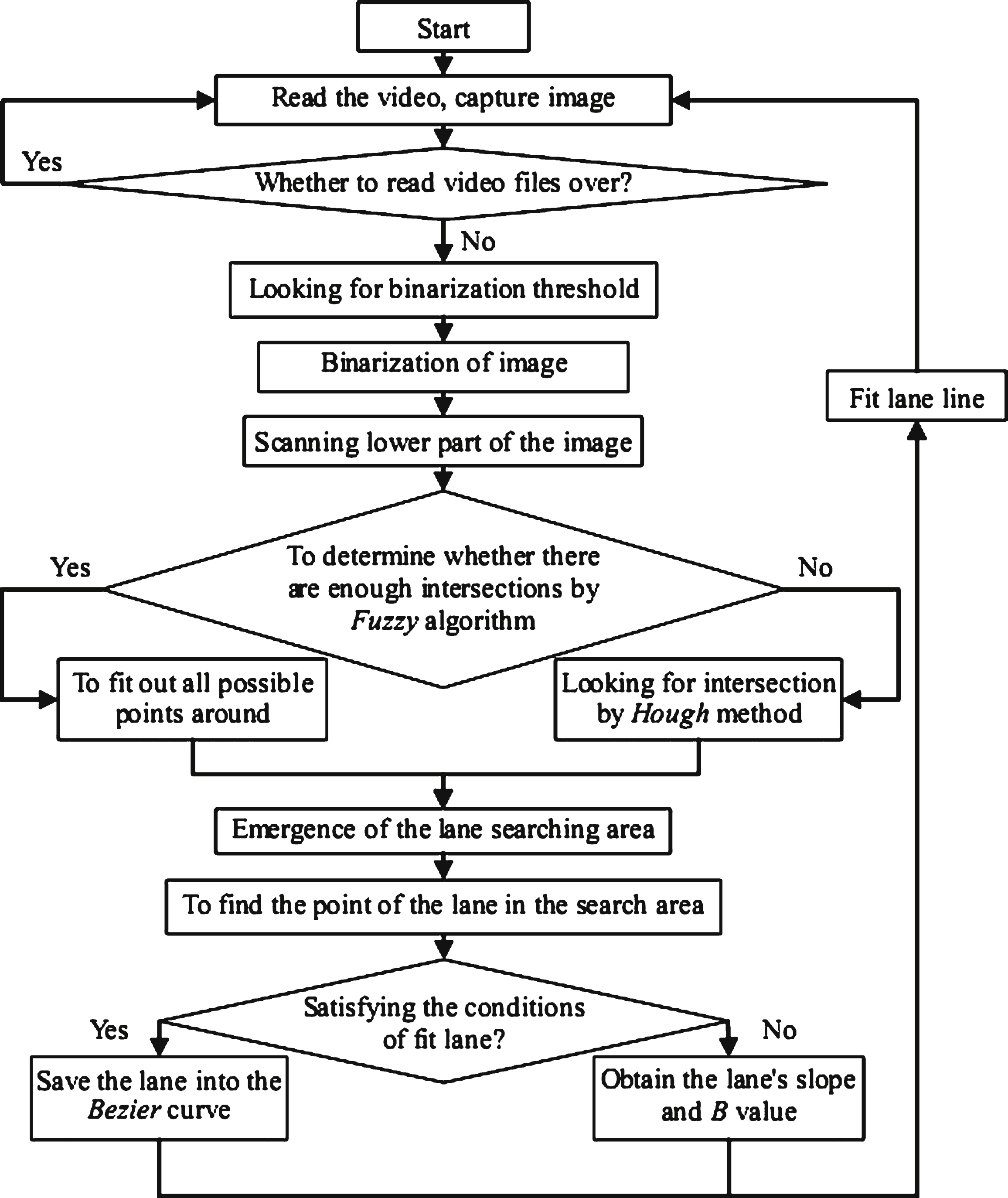
Fig.2
The intersection of lane and image edge.
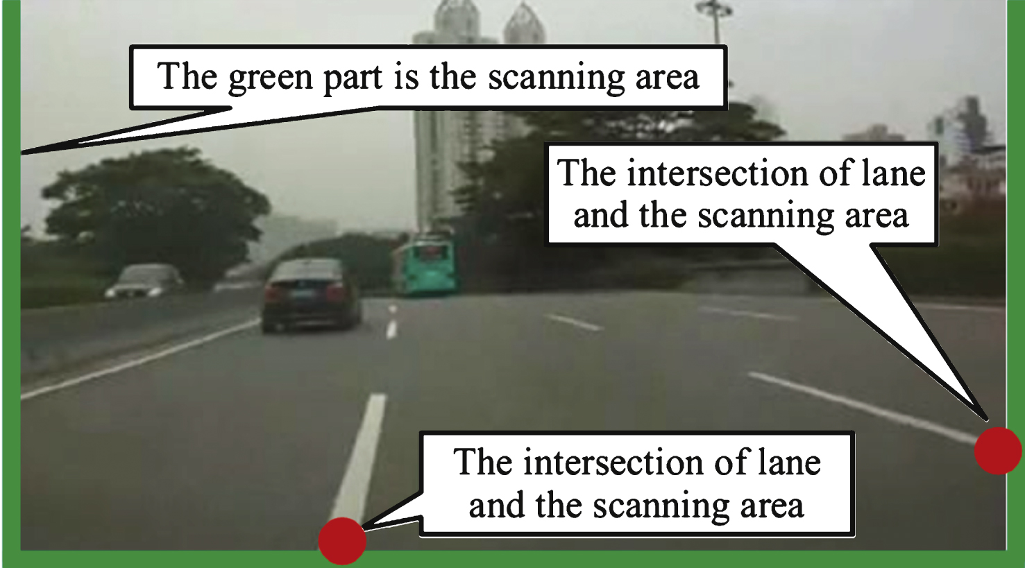
Fig.3
Lower part of image block processing.
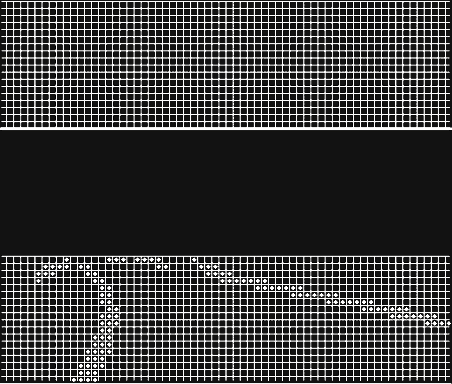
Fig.4
Obtain lost intersections.
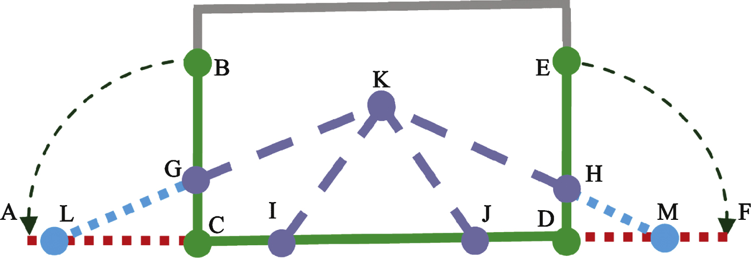
Fig.5
The intersections of lane and image edge that had not been originally detected.
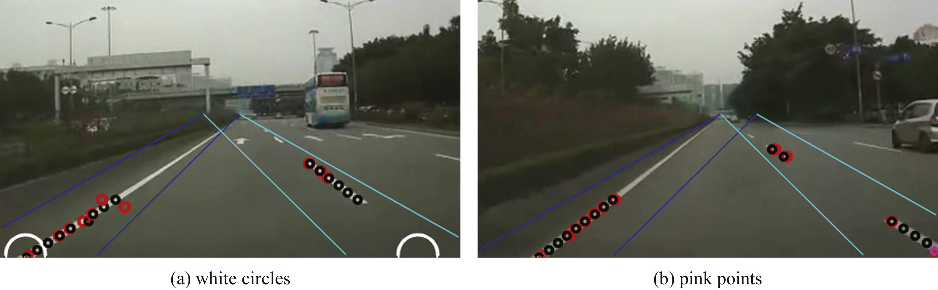
Fig.6
Fitting the lane lines.
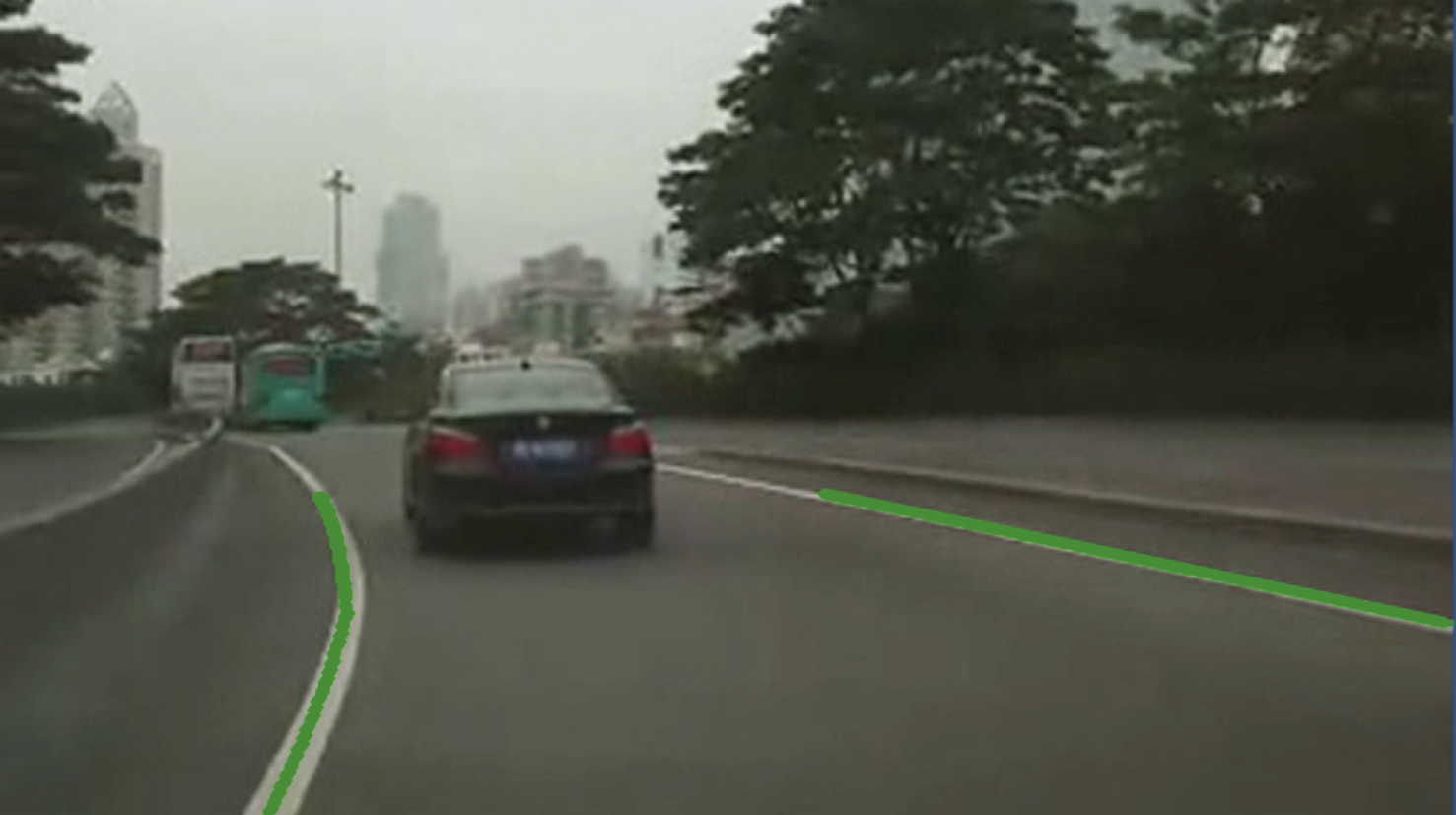
Table 1
Fuzzy logic rules
| DPC | DPN | DPF | |
| DVC | SAN | SAN | CV |
| DVN | SAN | MS | CV |
| DVF | CV | CV | CV |
Table 2
Performances of real-time experiments
| Tests | NF | TT | TF | MaxTF |
| test 1 | 917 | 20022.3001 | 21.8346 | 31.0101 |
| test 2 | 917 | 19118.9022 | 20.8549 | 32.7083 |
| test 3 | 917 | 21616.2252 | 23.5728 | 36.3838 |
| test 4 | 917 | 10581.3392 | 11.5391 | 28.9889 |
| test 5 | 771 | 18415.7394 | 23.8855 | 29.1436 |
| test 6 | 917 | 10567.0074 | 11.5235 | 20.9310 |
| test 7 | 770 | 8536.0154 | 11.0857 | 18.7122 |
| test 8 | 917 | 10442.7475 | 11.3879 | 14.3539 |
| test 9 | 2790 | 57312.4483 | 20.5421 | 30.9945 |
| test 10 | 917 | 10465.6404 | 11.4129 | 19.6281 |


