
A research method to capture design state based on multi-fuzzy cognitive mapping
Abstract
Designer thinking has received much attention as an innovative problem-solving approach. However, it is also a vague and unclear activity which can only be studied through the input and output results in a design process. This paper proposes that the visual design state is the external performance of design thinking, which is used to clarify vague design thinking. In this paper, a method for expressing and capturing design states based on multi-fuzzy cognitive mapping is presented. First, an agent model is built to capture the design states, and the weight values of the multi-fuzzy cognitive map matrix are calculated. The tightness of the design state route is then deduced. An example is presented to demonstrate the use of this method, which is able to support the designer with the necessary design resources and an intelligent design environment.
1Introduction
Designing emphasizes innovation of new products, which originates in designer thinking; therefore, the designer’s creative thinking is a determinant for the innovative solutions in the product design process [20]. The product design process consists of sequential design states; the current design state evolves into the subsequent one as the design progresses, and designer thinking develops largely based on the knowledge and experience of the designer. The design tools will provide timely and non-redundant resources if it is able to accurately capture the designer’s thinking [11].
Over the last few decades, most relevant research on identifying and capturing designer thinking during the product design process has focused on sketching, such as deducing the intention of the designer by recognizing gestures and strokes. For example, a sketch recognition system was developed to automatically transform symbolic shapes which originated from designer thinking into a shape recognizer, editing recognizer, and shape exhibitors [19]. Design activity and events from professional software designers were recorded and captured, and then visual syntactic elements in sketches were indicated to explain the designer’s thinking [13]. In addition, a 3D reconstruction method [15] and a 3D prototyping system to identify sketch profiles were also studied and developed [12]. Input from the mouse or keyboard was matched with the designer’s sketched intention to build 3D models.
Capturing a designer’s thinking is possible not only in the sketching stage, but also throughout the product design process, such as during the detailed design stage or the model construction stage [7]. Chang and Duo [21] provided a method for extracting design information in Computer Aided Design. This method describes a semantic representation framework for describing a design based on an ontology and resource description framework. The Do from Design Machine Group at the University of Washington proposed the “Right Time Tight Tools” in architectural design [8, 9], and converted and summarized design symbols from the designer’s thinking which can be identified by a computer system for architectural design. Do studied the role of designer thinking in a design process, but described it in symbols limited to architectural design. These symbols are difficult to remember and promote, so that this method for capturing designer thinking can work only for some designers. Researchers at Massachusetts Institute of Technology (MIT) and Brunel University posited that designer thinking could not be fully expressed by traditional interactions (such as with a mouse and keyboard). They proposed an interactive method of eyesight tracking and voice recognition, not simply the capture of strokes and gestures during sketching to capture the designer’s thinking. They studied the capture of designer thinking with the interactive methods, but did not take into account that the design process consists of multiple design states. Therefore, their research aim to capture designer thinking does not provide the most suitable auxiliary for designer [4, 10].
Other studies [2, 5] have proposed decomposition of the design process into a design network or tree. The neurons of the network or the nodes of the tree contain descriptive information about the design process (such as input and output operations, model data, design tasks and objectives), which are integrated into specific operations for models and aided tools recorded by the designer to capture design traces. This method was prototyped as a design tree for a CAD tool. Other studies [6, 16] have focused on the base of the design process, design units, and understand the design process as an event chain. According to this perspective, the design process is actually composed of linear chains of design events, including the operation of the design tools and models.
All the above literature demonstrates the importance of a designer’s thinking for a design process according to different methods, with different efficiency and application limitations. This paper explores the smallest design unit, which is the design state in the design process, and proposes that the design state is the external performance of a designer’s thinking, which drives the design state forward. Thus, the visual design state is used to clarify vague design thinking. To express and capture the design states better, a fuzzy cognitive map is introduced and proposed.
2Fuzzy Cognitive Map and Multi-Fuzzy Cognitive Map
A Fuzzy Cognitive Map (FCM) was proposed by Kosygin in the field of artificial intelligence in 1986 based on fuzzy and cognitive maps [3]. It is a directed graph linked by nodes and edges with arrows, which are used to indicate concepts and relationships between concepts, respectively. Concepts are used to express the states, actions, aims and results in a system, and relationships between concepts can express reasoning and feedback relationships. The node from which an arrow starts is called a forward-node or forward-concept, and the node to which an arrow points is called a backward-node or backward-concept. The state value of a backward-concept is decided by the forward-node, and the relationships related to it. FCM is able to clearly show the structural relationships in built systems. In particular, it makes full use of prior knowledge to support the system’s adaptive behavior [22].
Although the traditional FCM has many advantages, it can only express simple causality and cannot express AND, non-symmetric or non-monotonic causality. Since a designer’s thinking is very vague, this results in strong uncertainty in the design states. Causal relationships among the spatial concepts demonstrate strong sequential character. Furthermore, FCM cannot describe multiple sequential levels of causal relationships among concepts. Instead, the mufti-fuzzy cognitive map is proposed in this paper to express the design states in a product design process.
2.1Multi-Fuzzy Cognitive Map and its characteristics
Multi-Fuzzy Cognitive Mapping (MFCM) is similar to a neural network (NN) in structure and function, while the nodes of MFCM and their connections are more fuzzy, semantic and consequential, so that they can describe more semantic design states which have spatial and temporal characteristics [17].
2.1.1Concepts set
Definition 1. A concepts set, also known as the nodes set, is a collection of cognitive map nodes, and is denoted: S = {S 1, S 2 … S i … S j … S k … S n }. If the state change of node S j is caused by the shift of node S i , S i is designated the reason concept, and S j is the result concept. If S k is the ultimate design result, it is identified as the target concept. Mufti-level concepts of fuzzy cognitive maps are not single relationships between two nodes, but a many-to-one mapping relationship, which is one of the characteristics of multi-fuzzy cognitive maps. In this paper, the design states are expressed by the concepts of MFCM.
2.1.2Relationship between concepts and concept weight
In S = {S 1, S 2 … S i … S j … S k … S n }, the concepts are connected by edges. Assuming that S i and S j are connected by E ij , and the reasoning relationship between S i and S j is controlled by the concept weight W ij , the reasoning process is described in next part.
2.2The relationship among the concepts of MFCM
The relationship of MFCM may connect more than two concepts; there are three types of possible relationship among the concepts.
Definition 2. If the change of S j is caused only by S i without influence from another concept, then the relationship between S i and S j is considered to be direct causality.
Definition 3. If there is not a direct causal relationship between S i and S j , but they can be connected by S x , S y and S z concepts (S x , S y , and S z are all elements of set S), then S j and S i are considered to be a multi-tiered causal relationship. In the design process, most design states have multi-tiered causal relationships.
Definition 4. Context can currently explain the statement and assertion reasonably, and solve the ambiguous problems. Generally, context refers to the involved environment or situation for a statement, which may be one or several arguments, operations, speculations, or the relevant states in this paper [18]. In this paper, context is defined as the relationship among concepts of MFCM. If the concepts are not multi-tiered but have time series relationships, then this kind of relationship is called a context relationship, which gives the concepts layout the characteristic of time and space in MFCM, which are also the base of weighting values.
MFCM describes the causality and interaction among all the internal objects in the system. On this basis, the reason states relationship weight falls between the value [0, 1], which deals with different types and accuracy of vague information. Design states of MFCM are built based on their characteristics, as shown in Fig. 1.
3Capture agent model for design state based on MFCM
Concepts and relationships among them in MFCM constitute the internal structure of the capture agent. In a design process, the capture agent for a design state can be modeled as a binary group, Agent MFCM = {S, W} [14], in which concept “S” is a design states, and its weight “W” is expressed by a value that indicates the relationship intensity among the context concepts. S = {S 1, S 2 … S i … S j … S k … S n } is a design state set, where n is the number of the design states in the set. W = {W ij /W ij ∈ [0, 1] ; i, = 1, 2 … n} j is the probability from one state to the others, and its values constitute a relationship weight matrix, shown in Formula (1):
(1)
In the matrix above, m ≤ n. Wij = W (S i , S j ), in which S i and S j are two state nodes which are connected; S i is the forward node, and S j is the back node. W ij is the possibility from S i to S j , with a value range of [0, 1]. If W ij = 0, suggesting no possibility of a relationship between S i and S j ; if W ij = 1, it suggests that this route from S i to S j has the highest frequency.
4Reasoning the design state based on MFCM
4.1Design state reasoning function
In Agent MFCM , S indicates the internal attribute of the agent, and W represents their correlativity and interaction [1]. In fact, if all the forward design states related to design state S j are obtained, the highest possibility can be calculated, indicating the designer’s operation habits. Then, corresponding tools are provided to automatically drive S j-1 to S j .
The function of design state reasoning is shown in Formula (2).
(2)
4.2Weight value reasoning
Influenced by the design objects, external environment, the knowledge of the designer, assistance from tools, and the designer’s emotion, the same designer may have different thinking and input habits. There will be much necessary thinking to drive the design state from the beginning to the end, which constitutes different design state routes. Alternatively, the designer’s continuous thinking leads to every design state route, which constitutes a special scheduling chain structure that has not only a mainline but also branches in MFCM. The most important factor is that the associated link exists among only concepts, rather than only to the next concept. Based on the above, weight values are gradually to represent the context relationship. In the model Agent mfcm = {S, W}, the route set is defined as R. The elements of set R come from the edges connecting the state nodes, so that the weight value of W is determined by R.
Definition 5. Design state set [S = {S 1, S 2, . . . S i . . . S j . . . S n } builds MFCM, where S 1 is the first concept in MFMC, S n is the last concept, and there are a total of n concepts. Assume that S i is the ith design state, and S j is the jth design state. Define R 1-n as the design state route set S = {S 1, S 2, . . . S i . . . S j . . . S n } R 1-n = {R 1, R 2, … R k , … R m , 1 ≤ k ≤ m}, and R k is any one route connecting S 1 and S n . There are m routes in R 1-n , in which R k (1 ≤ k ≤ m) consists of some design states, that are also the concepts of MFCM, R k = {S 1 → S a , … S i → S j , … S b → S n } = {E 1a , … E ij , … E bn }. S a , S b , S i and S j are any one of node in MFCM, S i , S j , S a , S b ∈ S, probably S a = S i , S j = S b , 1 ≤ a, b, i, j ≤ n, so it requires at least one step from S 1 to S n , and there is at least one design state route. Sometimes, the designer may return to previous states for some reason during the design process, so there may be two S i or S j in R k , but only one S 1 and S n in R k . This is because the first state is an empty sketch, while the last one is the design result. Agent MFCM records the frequency of every passing node. The route runs with the minimum number of concepts at the highest efficiency, which may not be the result; only the route of highest frequency is the solution, which is relative to the tightness of the design state route.
Definition 6. The tightness of design state route R is the correlativity degree of a route in the MFCM; it includes all weight values of the state nodes. The formula to calculate W (R) is shown below:
(3)
(4)
In this paper, W ij is calculated with the mean value of probability. In fact, once the designer uses the system several times, the agent model records their operations and corresponding design states. Then, the system can re-calculate the weight probability according to the designer’s operation.
Formula (4) is suitable to the route forward, but sometimes the designer may return to some state node. For the route R 1 = {S 1 → S a , … S x → S y → S x → S z , … S b → S n }, Formulas (3) and (4) cannot resolve this situation. Returning requires giving up the present state, which may not pass again in this route. For this, a modifier can be applied as described below:
(5)
(6)
At last, the maximum of W (R k ) is calculated as follows:
(7)
R max represents the highest frequency route, and the desired result.
5Example application and analysis
According to the research method introduced in this paper, Agent MFCM is used to capture the design states. Here is an example of a table lamp design (see Fig. 2). The design involves nine states from the initial sketch to the result. The designer finishes the base and support, followed by the shade, and Agent MFCM records all the design operations and routes, which form the MFCM with multi-level and context relationships (see Fig. 3).
The weight values of this MFCM are calculated according to Formulas (4) and (6), and are placed into the weight value matrix (see Fig. 4). Then, W
(
R) can be obtained by Formulas (5) and (6). There are six routes in the set R = {R
1, R
2, R
3, R
4, R
5, R
6}, and their tightness values of design state routes are shown in Table 1, where W
27 has two values due to a return step from S
3 to S
2 in R
4. W
27 must be transformed to
The result of calculation is that R 1, R 5 and R 6 have the same maximum, indicating that they are all routes of the highest frequency, which involve both E 78 and E 89, and W 78 = 1, W 89 = 1, Only “shell” and “fillet” tools are necessary for states S 7 and S 8. Assistance from these tools drives both states to S 9, and other tools should be hidden.
The example aims to demonstrate the principle of the proposed method. Hence, there are relatively few steps in the example above, resulting in more than one outcome. In practice, designers would clearly see the intelligent guides of the method through an application of adequate steps. However, if there are enough steps in the design route, the range of results of routes of the highest frequency may be narrowed down, perhaps leaving only one route, which highlights the advantage of this method. In addition, the method proposed in this paper permits the designer to return in the design process, but the design route cannot be repeated again, so that the modifier Formulas (5) and (6) are presented. In reality, the designer can repeat the same design route unlimited times.
6Conclusion
This paper proposed the concept of a Multi-Fuzzy Cognitive Map, summarized its structure and its characteristics, and analyzed the relationships among the concepts of the MFCM. An expression of invisible designer thinking with visible design state was presented, as was a method to capture the design state based on MFCM. In this method, Agent MFCM is built to record all design routes, which form the MFCM and the weight matrix, and then the tightness values of design routes are calculated. Finally, the route of the highest frequency is determined and presented to the designer. The proposed method has the advantage of providing the designer with timing, necessary and non-redundant tools to aid the design process, and can drive intelligent navigation of the entire design process. Based on this, an intelligent design environment is built to support the designer to finish the design process quickly, so that product design time is decreased.
The formulas proposed in the paper to calculate the weight value of MFCM are set according to the average probability from one node to the others connected to it, which does not take the design habits of the designer into account. Further research will adjust the modification formula based on actual design routes after a designer uses this system several times, which will be more helpful to the designer.
Acknowledgments
The project was supported by the 111 Project of China (B13044).
References
1 | Padovitz A, Loke SW, Zaslavsky A (2008) Multiple-Agent perspectives in reasoning about situations for context-aware pervasive computing systems IEEE Transactions on systems, man, and cybernetics-part A: Systems and human 38: 4 729 742 |
2 | Bliem B, Morak M, Woltran S (2012) D-FLAT: Declarative problem solving using tree decompositions and answer-set programming Theory and practice of Logic Programming 12: 445 464 |
3 | Kosko B (1986) Fuzzy cognitive maps International Journal of Man-Machine Studies 24: 1 165 175 |
4 | Lawson B, Sassanian M, Phi M, Washington J (2003) Intentions practices and aspirations: Understanding learning in design, Design Studies 24: 4 327 339 |
5 | Costello DJ, Fraga ES, Killing N (1996) Epee: A Support Environment for Process Engineering Software Computer & Chemical Engineering 20: 12 1399 1412 |
6 | Dickerson , Charles E, Mavris Dimitri (2013) A brief history of models and model based systems engineering and the case for relational orientation IEEE Systems Journal 7: 4 581 592 |
7 | Ostrosi EH, HFougères A-JH, M. HFerney M, HKlein D (2012) A fuzzy configuration Multi-agent approach for product family modeling in conceptual design Journal of Intelligent Manufacturing 23: 6 2565 2586 |
8 | and E, Do Y-L (1998) The Right Tool at the Right Time–Investigation of Freehand Drawing as an Interface to Knowledge Based Design Tools, Ph. D. Dissertation Georgia Institute of Technology |
9 | E , Do Y-L, Gross MD, Gaiman B, Zinging C (2000) Intentions in and relations among design drawings Design Studies 21: 5 483 503 |
10 | Gharib , Islam Qin, Shengfeng (2013) Integration of sketch-based conceptual design and commercial CAD systems for manufacturing International Journal of Advanced Manufacturing Technology 68: 9 2669 2681 |
11 | Jabrouni H, Kamsu-Foguem B, Geneste L, Vaysse C (2011) Continuous improvement through knowledge-guided analysis in experience feedback Engineering Applications of Artificial Intelligence 24: 5 1419 1431 |
12 | He L, Fang G, Kong F (2007) Sketching Feature Based Modeling by Capturing Design Intention Journal of Computer Aided Design & Compute 19: 6 730 735 |
13 | Sun LY, Xiang W, Chai CL, Zhang KL (2014) Designers’ perception during sketching: An examination of Creative Segment theory using eye movements Designer Studies 35: 6 593 613 |
14 | Ammar M, Bouaziz S, Adel M, Alimi , Abraham , Ajith (2014) Multi-agent evolutionary design of Flexible Beta Basis Function Neural Tree, Proceedings of the International Joint Conference on Neural Networks 1265 1271 Beijing (China) |
15 | Contemn M, Maya F, Jorge J (2003) CIGRO: A minimal instruction set calligraphic Interface for sketch-based modeling, International Conference on Computational Science and Its Applications (ICCSA 2003) 549 558 Entreating, Canada |
16 | Remenska Daniela, Templon Jeff, Willemse AC, Tim Homburg, Philip Verstoep, Kees Casajus, Bal Adria Henri (2013) From UML to process algebra and back: An automated approach to model-checking software design artifacts of concurrent systems, NFM CA, U S A NASA Formal Methods-5th International Symposium 244 260 |
17 | Sethukkarasi R, Ganapathy S, Yogesh P, Kannan A (2014) An intelligent neuro fuzzy temporal knowledge representation model for mining temporal patterns Journal of Intelligent and Fuzzy Systems 26: 3 1167 1178 |
18 | Satur R, Liu Z, Gahegan M (1995) Multi-layered FCMs applied to context dependent learning Proceedings of 4th IEEE International Conference on Fuzzy Systems 561 568 Yokohama (Japan) |
19 | Hammond TR, Davis RH (2004) Automatically transforming symbolic shape descriptions for use in sketch recognition Proceedings of 19th National Conference on Artificial Intelligence 450 456 San Jose, Canada |
20 | Li X, Li Y, Pan P, Li W (2011) Research on computer-aided creative design platform based on creativity model Expert Systems with Applications 38: 9973 9990 |
21 | Chang Y, Duo X, Fan C (2011) semantic representation for asbly design intent Computer Integrated Manufacturing Systems 17: 2 248 255 |
22 | Li Z, Saturate R (1999) Contextual fuzzy cogonitive map for design support in geographic information Systems IEEE Transactions on Fuzzy System 7: 495 507 |
Figures and Tables
Fig.1
Design state MFCM.
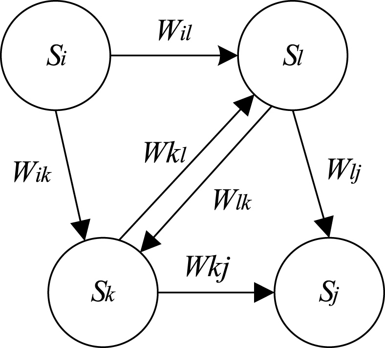
Fig.2
Nine design states for lamp shade.
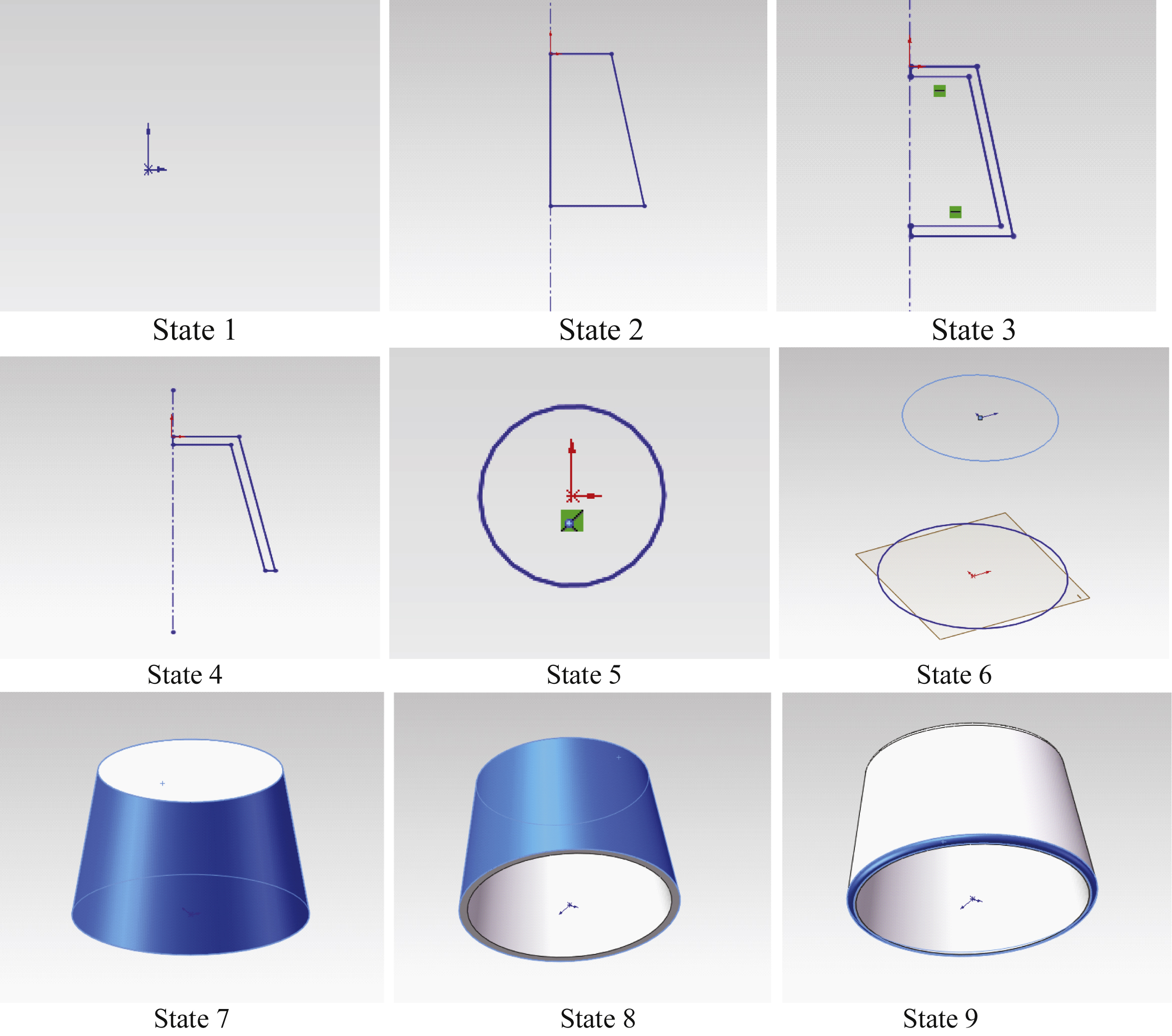
Fig.3
Design state MFCM for lamp shade.
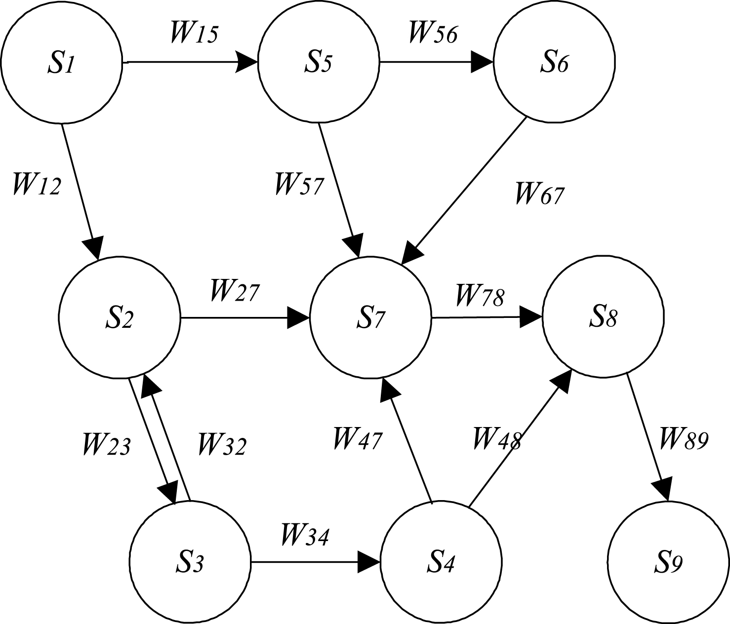
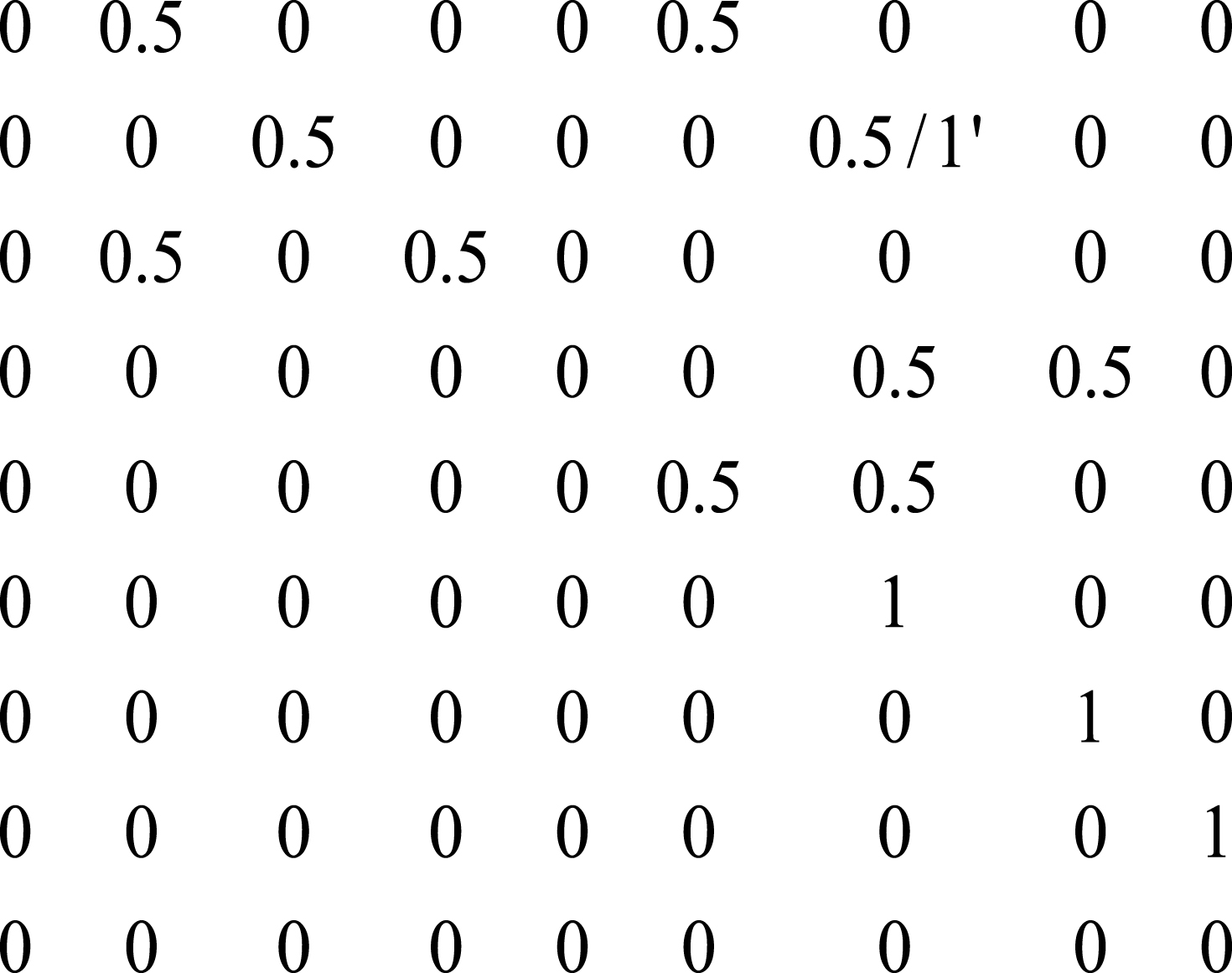
Table 1
The frequency of design routes in MFCM in Fig. 1
| R i | Elements of R i | W (R i ) |
| R 1 |
| 0.25 |
| R 2 |
| 0.125 |
| R 3 |
| 0.125 |
| R 4 |
| 0.125 |
| R 5 |
| 0.25 |
| R 6 |
| 0.25 |


