
A novel fuzzy-logic based control strategy for a semi-active battery/super-capacitor hybrid energy storage system in vehicular applications
Abstract
A hybrid energy storage system (HESS) composed of a battery and super-capacitor (SC) can make full use of advantages in energy and power density, which can further improve the performance of hybrid electric vehicles (HEV). Most studies have been limited to configuration and control to reduce the burden and prolong the life cycle of the battery, seldom focusing on the redesign of energy management strategies (EMS) for HEVs when passing from battery-only energy storage to HESS. In this paper, the equivalent fuel consumption during parallel-charging of a semi-active HESS in a series-parallel HEV under rule-based EMS was deduced, and a fuzzy-logic based (FLB) CS for the HESS was established using the state of energy (SOE) of the battery and SC as inputs. This allows the requirement of energy balance for HESS to be clearly expressed. Furthermore, the regulated EMS for HEV, which could dynamically manage the high efficiency of the engine and maintain the real-time charging/discharging capability of HESS, was proposed and verified under hardware in a loop test (HIL). Quantitative comparison of results between HESS and battery-only indicated that velocity-based SC’SOE-adjustable EMS presented in this paper could make better use of SC in filtering than SOE-constant EMS, and improve the fuel economy of HEVs from 22.76 l/100 km (battery-only) to 21.18 l/100 km. In order to emphasize the advantages of management, the electric energy usage/loss and efficiency under city driving-cycle were also presented.
1Introduction
Hybrid energy storage systems (HESS) composed of a battery and super-capacitor (SC) can utilize advantages in energy and power density simultaneously, and have attracted a great deal of attention in recent years [9, 14, 18, 20, 21]. There are three major types: passive, semi- and fully-active in the development of Hybrid Electric Vehicles (HEVs), Electric Vehicles (EVs) and Fuel Cell Vehicles (FCV) [20, 21]. All the primary purpose is to determine the use of SC as a filter to reduce the burden and prolong the life cycle of the battery to its maximum capabilities [14, 18, 20]. From the costs and the actual filtering effects, the active topology with one DC/DC converter, which is called a semi-active HESS, is often used in practical engineering. The DC/DC can regulate the voltage of the battery and SC at the same time, and controls the power flow as needed [9]. In this paper, a series-parallel HEV with a semi-active HESS was adopted as a case study. Taking into account the efficiency loss in DC/DC, the SC is directly connected to the terminal of the electric motor (EM) inverter and works as a buffer against large magnitudes and rapid fluctuations in power, whereas the battery connected to DC/DC is protected and the energy flow can be effectively controlled. However, in this topology, the DC link voltage must be allowed to fluctuate in a wider range so that the SC can be fully utilized in filtering. Furthermore, more attention should be paid to energy management strategies (EMS), which can maintain the charging/discharging capability of HESS in real time, and coordinate with the power-train control to keep the engine working efficiently [5, 9].
The objectives of this paper are as follows:
1. To clarify the performance of HESS and its relationship to HEV. Rule-based power split EMS of HEV was proposed, in which EM parallel charging and assisting envelops separated the engine fuel map contour into three working regions: engine only, EM parallel charging and EM assisting. A novel adjustment method of optimizing engine operating points was proposed in combination with the efficiency of the battery/SC under different charging/discharging powers.
2. To propose a control strategy (CS) of HESS which could maintain high performance and adjust the EMS of the HEV, according to the demand and urgency of energy balance based on SOE of the battery/SC. A novel fuzzy logic based (FLB) energy balance CS of HESS was proposed to efficiently regulate the EMS of HEVs and simultaneously maintain the charging/discharging ability of HESS. Using SOE of the battery and SC as inputs and standardized fuzzy membership function as outputs, this method could be easy translated to vehicles with same topology but different parameters.
3. To determine the control law which can make full use of SC in filtering and deduce the energy loss when the battery participates in work. A novel adjustable membership function algorithm based on velocity was developed, which ensured that the energy stored in SC could be utilized effectively during EV and regenerate mode.
2System description and EMS
2.1Series-parallel HEV with HESS
The configuration and parameters of the series-parallel HEV with HESS proposed in this paper are shown in Fig. 1 and Table 1. The power-train consists of the engine, integrated starter/generator (ISG), clutch, electric motor (EM), and transmission. Accessories such as air conditioning and vacuum boosters are electrically driven. The battery and SC are combined into a semi-active HESS through an H-bridge Buck/Boost DC/DC to supply power while driving or regenerating. Within the HESS, the DC/DC converter is typically the interface between the battery and the DC-link bus voltage, and manages the entire amount of power through the battery.
2.2Rule-based power split strategy
For the HEV, the engine will operate in a comparatively high-efficiency region. EM parallel charging and EM assisting envelopes separate the engine BSFC shown in Fig. 2 into three regions: engine only, EM parallel charging and EM assisting regions [13].
For any power demand and engine speed, the optimal CS should be able to handle the switch between the three modes (engine only, EM parallel charging and EM assisting) with minimum fuel consumption [17].
1) The critical power of EM parallel charging
For an engine speed, the EM parallel charging power is the minimum power demand (Penginemin) when the working mode of the HEV switches from EM parallel charging to engine only. At this speed, for any power demand (Prequired) less than Penginemin, the fuel consumption in EM parallel charging mode is less than that in engine only mode. Therefore, for any Prequired less than Penginemin, Equation (1) can be established [8, 12, 13, 15, 17].
(1)
Equation (1) can be simplified as follows:
(2)
When Pmotor approaches 0, Equation (2) can be written as Equation (3).
As demonstrated by the equations above, for an engine speed, when the power demand is equal to Prequired, whether the fuel economy can be improved by using EM parallel charging is determined by the specific fuel consumption of the engine and the combined efficiency of the motor and HESS.
(3)
That is:
(4)
The EM efficiency is not the research focus in this paper, so the ɛm is assumed constant at 0.88. The efficiency of HESS ɛes is primary factor of investigation, because electricity can be stored in the battery or SC when charging. However, the charging efficiency of the battery and the SC is not the same. The nominal voltage of the battery used in this paper is 256 V, and the resistance is 0.09Ω. The voltage range of SC is 250 V–430 V, the average voltage is 340 V, and the resistance is 0.047Ω. The power loss and efficiency with the Rint model [7] of battery and SC under different charge powers are shown in Table 2.
As shown in Table 2, in the 0–30 kw range of charging power, the average charging efficiency of battery is 97.5% , and the average efficiency of SC is 99.3% . When charging battery, the power is doomed through DC/DC, whose average efficiency is 97% [11], so the battery efficiency is 94.6% eventually. Take the efficiency of battery and SC into Equation (4), and calculate the values of the left and right sides in Equation (4) varying by the output power of engine. The results are shown in Fig. 3.
As shown in Fig. 3, when calculated by the efficiency of the battery and the Prequired is less than 33 kw, the Equation (4) is workable. This indicates that when the Prequired is less than 33 kw, EM charging of the battery can reduce the fuel consumption and improve the efficiency of the power-train. However, when calculated by the efficiency of SC and the Prequired is less than 40 kw, Equation (4) is workable. This indicates that when then Prequired is less than 40 kw, EM charging of the SC can improve the efficiency of the power-train. Therefore, 33 kw and 40 kw is the critical power to charge the battery and the SC, respectively, at an engine speed of 1840 rpm.
2) Critical power of EM assisting
As shown in Fig. 2, at a certain speed, the specific fuel consumption of the engine decreases with increasing engine load. The specific fuel consumption will increase when EM assisting is used before the engine reaches its maximum output, so the critical power of EM assisting should be equal to the maximum engine power [19]; that is, EM assisting should not be used when the engine can meet the demand. The optimal efficiency boundary of the control mode switch can be obtained by combining with the EM parallel charging envelop, as shown in Fig. 4.
3Dynamic fuzzy logic based energy balance EMS
3.1Definition of SOE
To represent the demand urgency of HESS energy balance, SOE is defined as the energy state of the battery or SC, which is the ratio of available energy capacity to its range.
For the battery, the SOE can be expressed as follows:
For the SC, the SOE can be expressed as follows:
3.2FLB CS
In this paper, the maximum power of EM working in assisting or generating is 100 kw; therefore, the ideal SOE of HESS is the region that 5s of sustainable charge/discharge power can reach 100 kw [8]. Methods according to which may balance the energy of HESS include: regulation of EM parallel charging and assisting, EM limiting, and DC/DC controlling [13]. The fuzzy logic based EMS shown in Fig. 5 was adopted in this paper to design the energy balance strategy. The method of determining membership function is the use of intuitionistic fuzzy sets [6, 10]. The available energy of the battery or SC is normalized into five functions of S1 to S5, whose values are all between 0 and 1 [1, 4].
In order to avoid the energy losses between battery and SC conversion, the engine balance is primarily used to adjust the SOE of the battery and SC. When the SOE of SC is too high or too low, the DC/DC will be used to charge the SC, and the EMS will not use the SC to charge the battery [11].
3.2.1Regulation with SOEUC
Set the SOEUC into five statuses: lower, low, normal, high and upper status, whose membership functions are LLUC(SOEUC), LUC (SOEUC), NUC (SOEUC), HUC (SOEUC) and HHUC (SOEUC), respectively, as shown in Fig. 6.
As shown in Fig. 6, when the SOEUC is in the range of 0.3 to 0.7, the 5s sustainable power of SC can reach 100 kw, which will be set to the normal range for SC which indicates NUC is 1, so it is not necessary to adjust for the SOEUC for the vehicle control strategy.
When the SOEUC exceeds its normal range, NUC will decrease, indicating that the SOE is high or low. The power of engine generating or EM assisting should increase to balance SOEUC to its normal range. According to the membership function of the SOEUC for each state, the adjustment method of motor critical power PengineminUC is established as Equation (5) when SC is charging.
(5)
The adjustment method of critical power Pm on of EM assisting is established as follows:
(6)
When the SOEUC exceeds the range of 0.1 to 0.9, the HHUC and LLUC will increase from 0, which indicates that the SOEUC is nearing the upper or lower limit. As shown in Equations (5) and (6), Pengine_min UC and Pm_on have reached the limit that can be adjusted, which represents the ability of engine balancing to reach its maximum value. In order to prevent the SOEUC exceeding its working range of 0 to 1, the battery must work through DC/DC to assist the SC. Set the output power from SC to battery under boost mode. If DC/DC is positive, and the input power from SC to battery under buck mode is negative, the adjustment method of output power of DC/DC is established as follows:
(7)
(8)
(9)
3.2.2Regulation with the SOEbat
Using similar methods, the SOEbat will demonstrate low, normal and high statuses. The membershipfunctions of LBATNBAT HBAT are shown in Fig. 7.
Because the SOEbat has little influence on the discharge power of HESS and the available energy capacity is large enough, 0.1 to 0.9 is set as the normal range for SOEbat, and the NBAT is set to 1. The vehicle control strategy does not need to adjust to balance the battery. When the SOEbat exceed the normal range, the increase of HBAT or LBAT indicates that SOEbat is higher or lower, and it will need to adjust the SOEbat by the coordinate control of the engine and DC/DC.
The relationship between the critical power generation and the SOEbat is established by Equation (10) when battery is charging.
(10)
The relationship between the critical power of EM assisting and SOEBAT is established as follows:
(11)
The relationship between the power of DC/DC and SOEBAT is established as follows:
(12)
As shown in the above three equations, when SOEBAT exceeds its normal range, PengineminBAT can vary between 0% and 200% of PengineminBATR, and Pm on can vary between 75% and 100% of PmonR. The power of DC/DC can vary between its maximum boost and buck powers.
3.2.3Integrated FLB EMS
As shown in Equations (5) to (12), the power balance algorithm of HESS to adjust the vehicle control strategy by SOEBAT and SOEUC is finally established as shown in Equations (13) through (16).
As shown in Equations (5) and (10), the finalcritical power of Penginemin is determined to be the maximum value of PengineminUC and PengineminBAT, as shown in Equation (13).
(13)
As shown in Equations (6) and (11), the adjustment method of the final power critical value of EM assisting Pmon is written as:
(14)
As shown in Equations (7) to (12), the adjustment method of DC/DC power is written as:
(15)
(16)
Since the power of the motor is only related to SOEUC, Equations (8) and (10) are adopted as the algorithm to limit motor power in the controlstrategy.
3.3Vehicle speed based adjusting method
As the membership function graph of SOEUC shown in Fig. 6, the vehicle control strategy always balances SOEUC in the range of 0.3 to 0.7, with 0.5 as the midpoint. However, when the vehicle speed is low, electric driving and acceleration are needed, which require more discharge from HESS. While the vehicle speed is high, the vehicle tends to recover the potential energy from regenerative braking, which requires more energy charging to HESS. Therefore, in order to make full use of the storage of the SC, the vehicle speed-based SOEUC membership function adjusting method was established, as shown in Fig. 8.
To determine the value of 1 point in HUC and LUC in membership function, the following two principles should be followed: 1) SC should satisfy the demand before vehicle speed reaches 15 km/h in EV mode, while the SOEUC is not lower than 0.1; 2) there is enough energy space for energy recovery when regenerative braking at any velocity.
As shown in Fig. 8, 50% of the middle portion between HUC and LUC is considered to be the expected SOEUC normal range, where the function value of NUC is equal to 1. The points where SOEUC are equal to 0 and 1 still indicate that the values of HHUC and LLUC are 1.
4Experiment platform
A hardware-in-the-loop (HIL) experiment platform, shown in Fig. 9, was established to verify the control effect [16]. Dspace acts as a close-loop processor, the Driver model, EMS and Vehicle model all run in it. Using the target speed shown in driving cycle as input, and power demand to the battery simulator and tester (digatron) as output. The HIL could implement the real-time simulation and performance test of HEV with HESS.
4.1Power demand on HESS
The forces on acting on a vehicle can be divided into two types [2, 3, 13]: active and passive, according to their causes. Active force Ft is the ground force acting upon the vehicle, which is caused by the torques of motors and engine, expressed as:
(17)
The passive force FZ is the result of vehicle movement and slope, etc., expressed as:
(18)
Therefore, the total external force on the vehicle (FBUS) can be expressed as:
(19)
From the perspective of vehicle kinetics, the response equation between the vehicle speed and force can be written as:
(20)
In the vehicle dynamics model, PEM and PISG are motor mechanical power in real time, which are provided by HESS. By means of motor efficiency ɛm, the electric power provided by HESS was acquired, expressed as:
(21)
4.2Results and discussions
HIL was conducted using velocity as input, as shown in Fig. 10. Constant and varied SOEUC CSs of HESS were adopted for comparisons; after many repeat tests and design modifications, the average experimental results are shown below. Figure 10 depicts the velocity input and the SOE process. Table 3 depicts the quantitative comparisons between different CSs of HESS. In order to interpret the energy used during the cycle, energy usage was defined as the integration of absolute power of the battery and SC.
As the ellipse shows in Fig. 10, compared to constant CS, varied SOE CS could utilize more energy in SC at low velocity, which could provide more space for energy recovery produced in regeneration at medium and high speeds. Consequently, the results shown in Table 3 verified that HESS under FLB CS could improve the fuel economy of HEV from 22.76 l/100 km (battery only) to 21.47 (constant SOEUC) ∼21.18 (variable SOEUC) l/100 km. The energy loss reduction and efficiency improvement also remain consistent with fuel economy.
As shown in Fig. 10 and Table 3, the variation of SOESC with velocity-based adjustment is wider than the constant results, which indicates better use of SC. While reducing the usage of battery, this CS could reduce energy exchange for maintaining SOE among the engine, battery and SC, particularly the energy loss caused by the exchange between the batteryand SC.
5Conclusion
In this paper, a novel FLB CS for a semi-active battery/SC HESS in a series-parallel HEV application was proposed to efficiently regulate the EMS of HEV and simultaneously maintain the charging/discharging ability of HESS. In particular, The equivalent fuel consumption when parallel-charging for a semi-active HESS in a series-parallel HEV under rule-based EMS was deduced, and a fuzzy-logic based (FLB) energy balance CS for the HESS was established, using the state of energy (SOE) of the battery and SC as inputs and standardized fuzzy membership functions as outputs. The requirement of energy balance for HESS could then be clearly expressed. Furthermore, the regulated EMS for HEV, which could dynamically manage the high efficiency of engine and simultaneously maintain the real-time charging/discharging capability of HESS, was proposed and verified by hardware in looptest (HIL).
Quantitative comparison of results between HESS and battery-only tests indicated that velocity-based SC’SOE-adjustable EMS presented in this paper could make better use of the SC in filtering than SOE-constant EMS, and improve the fuel economy of HEV with a battery from 22.76 l/100 km (battery-only) to 21.18 l/100 km.
The HIL results have verified the potential benefits derived from the adoption of a dynamic fuzzy membership function, especially in the SOEUC adjustment algorithm based on velocity which can ensure that the energy stored in the SC can be utilized effectively during EV and regeneration mode. In order to emphasize the advantages of management, electric energy usage/loss and efficiency under city driving-cycles were also presented. As for the standardized inputs and outputs of CS, the method proposed in this paper could be easy translated to a vehicle with same topology but different parameters.
Acknowledgments
The authors gratefully acknowledge the financial support from the National Natural Science Foundation of China (51107052).
References
1 | Ferreira AA, Pomilio JA, Spiazzi G, de Araujo Silva L (2008) Energy management fuzzy logic supervisory for electric vehicle power supplies system IEEE Trans Power Electron 23: 1 107 115 |
2 | Santucci A, Sorniotti A, Lekakou C (2014) Power split strategies for hybrid energy storage systems for vehicular applications Journal power Sources 258 395 |
3 | Sciarretta A, Back M, Guzzella L (2004) Optimal control of parallel hybrid electric vehicles IEEE Trans Control Syst. Technol 12: 3 352 363 |
4 | Hredzak B, Agelidis VG, Jang M (2014) A Model predictive control system for a hybrid battery-ultracapacitor power source IEEE Trans Power Electron 29: 3 1469 1479 |
5 | Mid-Eum C, Seong-Woo K, Seung-Woo S (2012) Energy Management Optimization in a Battery/Supercapacitor Hybrid Energy Storage System IEEE Transactions 3: 1 463 472 |
6 | Iakovidis DK, Papageorgiou E (2013) Intuitionistic Fuzzy Cognitive Maps IEEE Transactions on fuzzy systems 21: 2 342 |
7 | Vinot E, Trigui R (2013) Optimal energy management of HEVs with hybrid storage system Energy Conversion and Management 76: 437 452 |
8 | Ali Borhan H, Vahidi A (2010) Model Predictive Control of a Power-split Hybrid Electric Vehicle with Combined Battery and Ultracapacitor Energy Storage American Control Conference 5031 5036 |
9 | Cao J, Emadi A (2012) A new battery/ultracapacitor hybrid energy storage system for electric, hybrid, and plug-in hybrid electric vehicles IEEE Trans Power Electron 27: 122 132 |
10 | Jeon JK, Jun YB, Park JH (2005) Intuitionist fuzzy alpha-continuity and intuitionist fuzzy precontinuity International Journal of mathematics and Mathematical Sciences 2005: 19 3091 3101 |
11 | Blanes JM, Gutierrez R, Garrigos A (2013) Electric Vehicle Battery Life Extension Using Ultracapacitors and an FPGA Controlled Interleaved Buck-Boost Converter IEEE Transactions on power electronics 28: 12 5940 5948 |
12 | Trovao JP, Pereirinha PG, Jorge HM, Antunes CH (2013) A multi-level energy management system for multi-source electric vehicles – an integrated rule based meta-heuristic approach Appl Energy 105: 304 318 |
13 | Liang JY, Zhang JL, Zhang X (2013) Energy management strategy for a parallel hybrid electric vehicle equipped with a battery/ultra-capacitor hybrid energy storage system Zhejiang Univ-Sci A (Appl Phys & Eng) 14: 8 535 553 |
14 | Ortuzar M, Moreno J, Dixon J (2007) Ultracapacitor-Based Auxiliary Energy System for an Electric Vehicle: Implementation and Evaluation IEEE Transactions on industrial electronics 54: 4 2147 2156 |
15 | Sivertsson M, Eriksson L (2014) Optimal transient control trajectories in diesel–Electric systems—Part II Generator and Energy Storage Effects Eng Gas Turbines Power 137: 2 021602 |
16 | O’Grondin L, Thibault C (2015) Quérel, Energy Management Strategies for Diesel Hybrid Electric Vehicle Oil & Gas Science and Technology – Rev, IFP Energies nouvelles 70: 1 125 141 |
17 | O’Simona L (2015) Tribioli, Adaptive Pontryagin’s Minimum Principle supervisory controller design for the plug-in hybrid GM Chevrolet Volt Applied Energy 147: 224 234 |
18 | Carter R, Cruden A, Hall PJ (2012) Optimizing for Effciency or Battery Life in a Battery/Supercapacitor Electric Vehicle IEEE Transaction on vehicular technology 61: 4 1526 1533 |
19 | Adhikari S, Saman K, Halgamuge S, Watson HC (2010) An Online Power-Balancing Strategy for a Parallel Hybrid Electric Vehicle Assisted by an Integrated Starter Generator IEEE Transactions on vehicular technology 59: 6 2689 2699 |
20 | Lhomme W, Delarue P, Barrade P, Bouscayrol A, Rufer A (2005) Design and control of a supercapacitor storage system for traction applications IEEE Industry applications conference - 40th IAS Annual Meeting 3: 2013 2020 |
21 | Kima Y, Kohb J, Xie Q, Wang YZ, Changb N, Pedram M (2014) A scalable and flexible hybrid energy storage system design and implementation Power Sources 255: 410 422 |
Figures and Tables
Fig.1
Configuration of the series-parallel HEV with HESS.
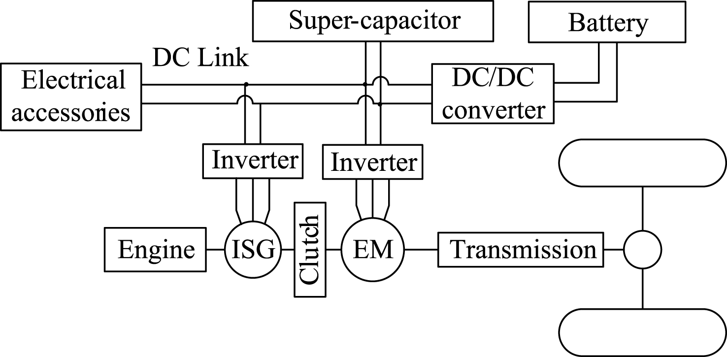
Fig.2
Fuel map contour of engine (BSFC) (g/kwh).
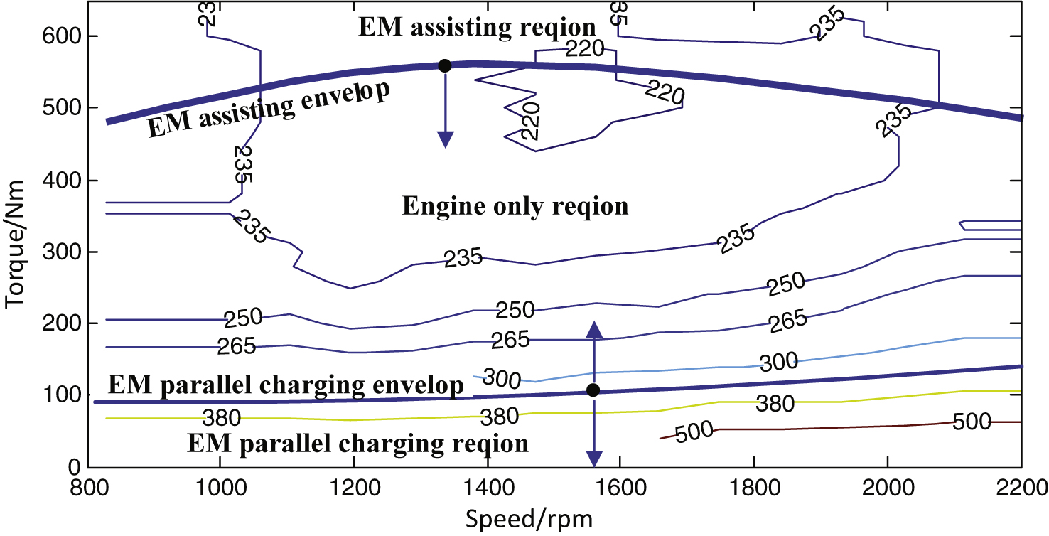
Fig.3
Optimum EM parallel charging power at 1840 rpm.
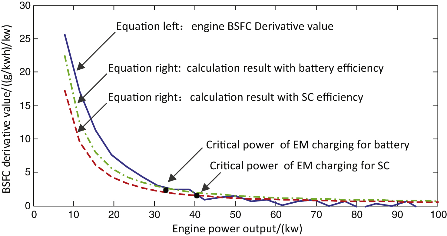
Fig.4
Control mode switching.
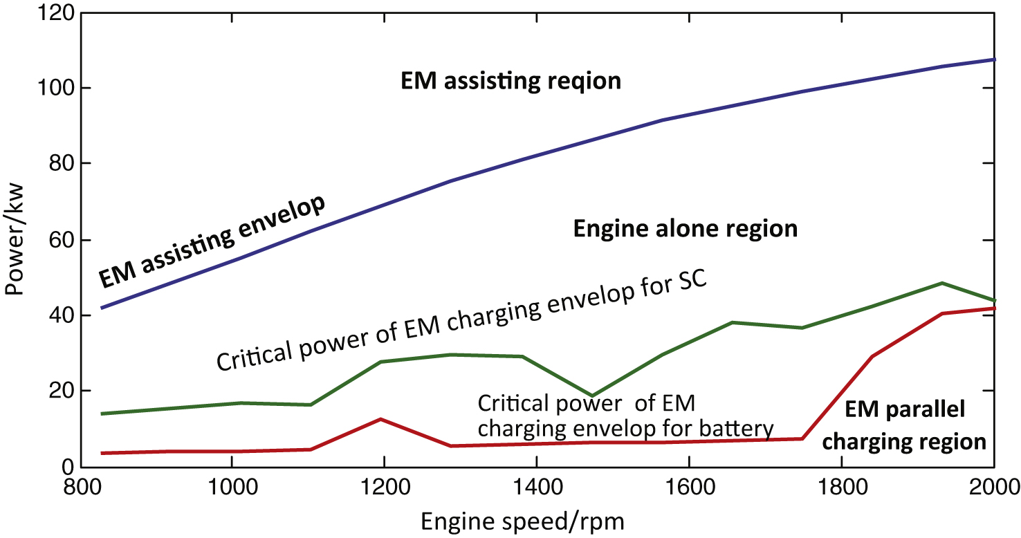
Fig.5
FLB energy balance strategy.
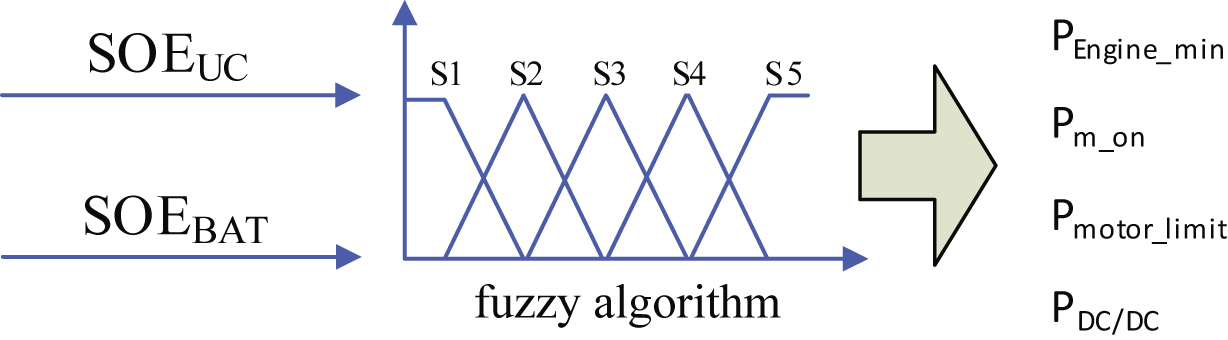
Fig.6
Membership functions of SOEUC.
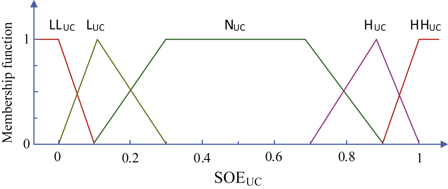
Fig.7
Membership functions of SOEBAT.
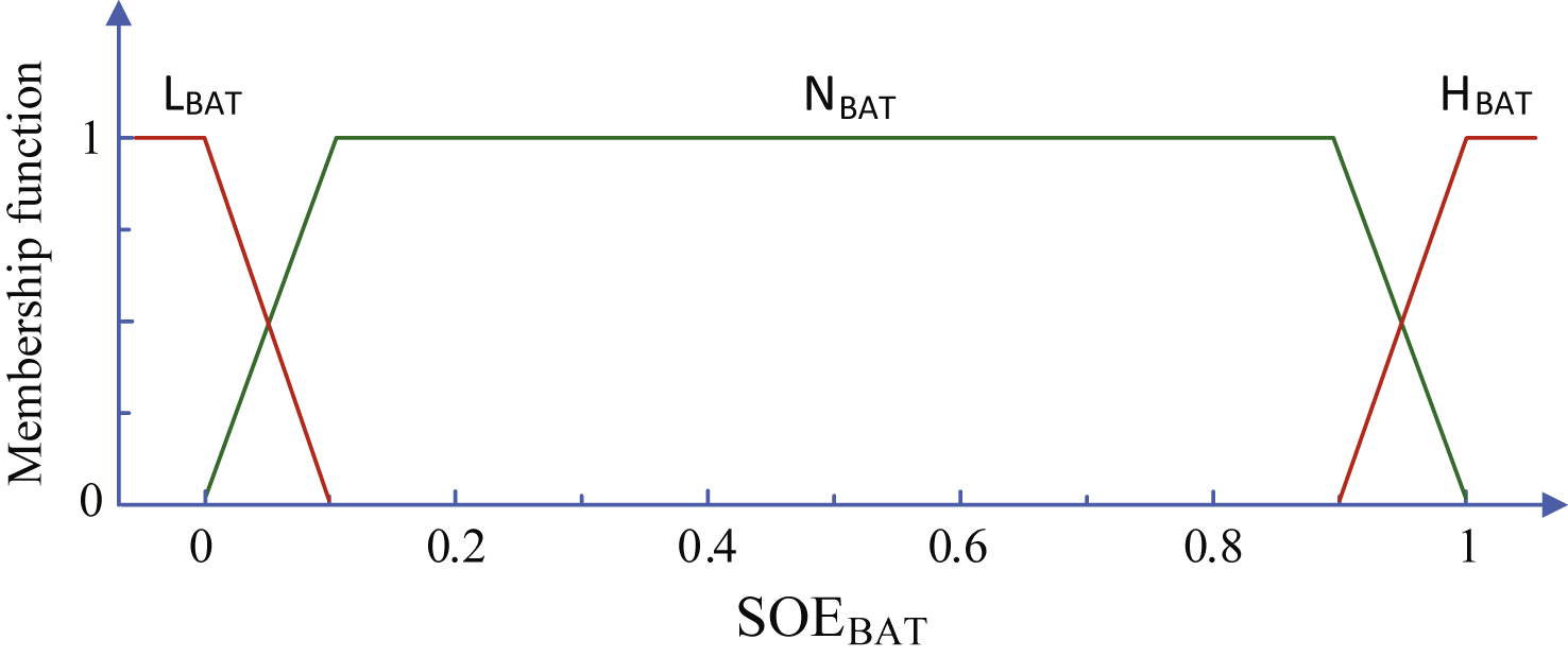
Fig.8
Velocity-based membership adjusts method.
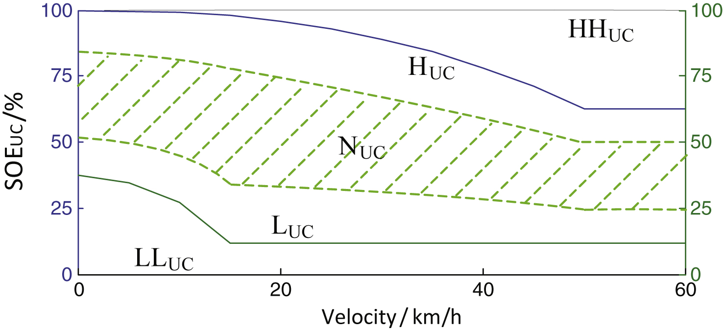
Fig.9
Real-time simulation and experimental platform for HEV/HESS.
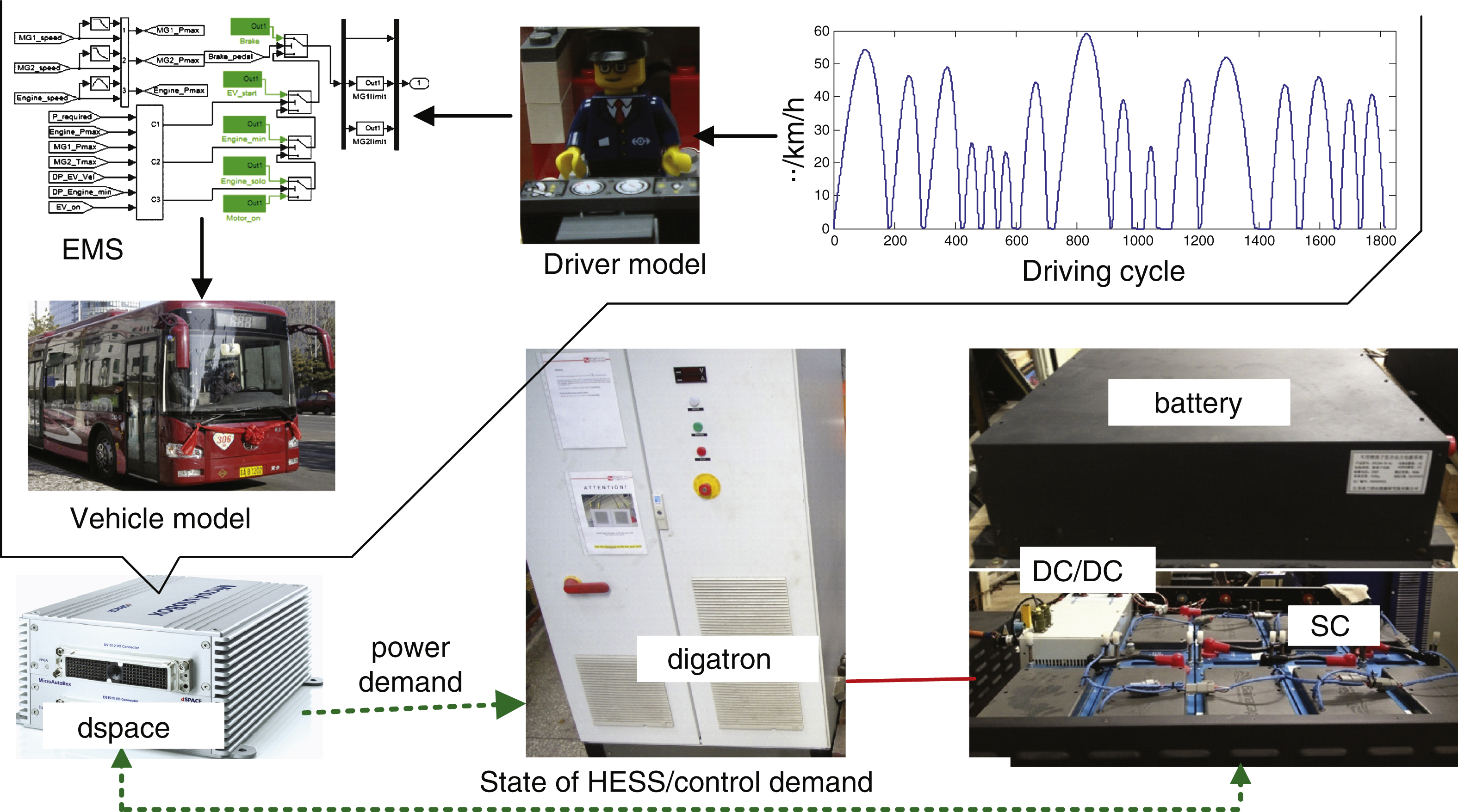
Fig.10
Variation of SOEUC between two CSs.
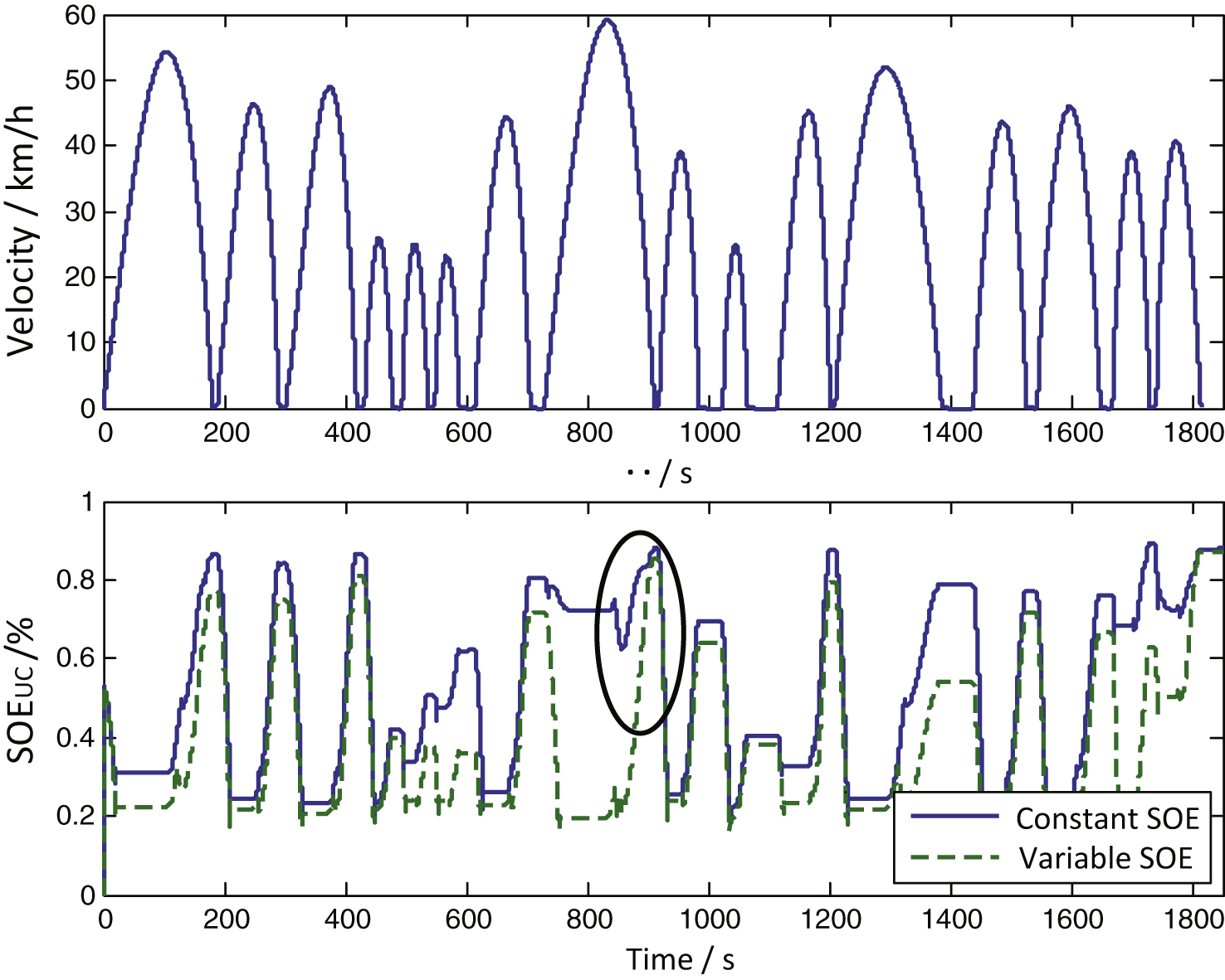
Table 1
HEV parameters
| Parameter | Value |
| Total mass | 18000 kg |
| Frontal area | 7.3 m2 |
| Wind resistance coefficient | 0.78 |
| Rolling resistance coefficient | 0.01 |
| Engine | 110 kw |
| ISG/EM | 20/100 kw |
| battery | 256 V/35Ah |
| SC | (250∼437 V)/18.5F |
| DC/DC converter | Buck /Boost 25 kw |
Table 2
The performance of battery/SC under different charging powers
| Charging power/kw | 5 | 10 | 15 | 20 | 25 | 30 | 35 | 40 | |
| battery | power loss/w | 33.7 | 134 | 296 | 520 | 802 | / | / | / |
| power loss rate/% | 0.7 | 1.3 | 2 | 2.6 | 3.2 | / | / | / | |
| efficiency/% | 99.3 | 98.7 | 98.0 | 97.4 | 96.8 | / | / | / | |
| SC | power loss/w | 10.1 | 40.5 | 90.9 | 161 | 251 | 361 | 491 | 640 |
| power loss rate /% | 0.2 | 0.4 | 0.6 | 0.8 | 1 | 1.2 | 1.4 | 1.6 | |
| eff/% | 99.8 | 99.6 | 99.4 | 99.2 | 99.0 | 98.8 | 98.6 | 98.4 |
Table 3
The HIL results of HEV with HESS/battery only
| ESS/CS | Energy usage | Energy loss | Efficiency | Fuel economy | |
| (kwh/100 km) | (kwh/100 km) | (%) | (l/100 km) | ||
| battery | SC | ||||
| variable SOEUC | 0 | 33.5 | 0.42 | 98.7 | 21.18 |
| constant SOEUC | 2.8 | 35.4 | 0.85 | 97.4 | 21.47 |
| Battery only (40 Ah/336 V) | 40.0 | 0 | 1.67 | 95.8 | 22.76 |


