
Stability analysis and fuzzy smith compensation control for semi-active suspension systems with time delay
Abstract
This paper investigates the problem of stability analysis and fuzzy-smith compensation control for semi-active suspension systems with time delay. The dynamic system of the suspension system with time delay is first formulated in terms of control objectives, such as ride comfort, road handling, and suspension deflection. By using the Lyapunov stability analysis, the necessary and sufficient condition of the critical time delay for the semi-active suspension is derived, and the numerical computation method of solving the asymptotic stability area for this suspension system is presented. Then, our work focuses on designing a Fuzzy-Smith predictive controller to satisfy suspension performance requirements. The control law adopted here is based on the smith predictive control principle, which ensures the control accuracy and stability of a time-delay suspension system. In order to overcome the challenging issues of the model uncertainties of input time delay, a Fuzzy-Smith predictive controller with time delay is established for the semi-active suspension. Furthermore, simulation and test results for the semi-active suspension are provided to demonstrate the effectiveness and feasibility of the proposed method.
1Introduction
Vehicle suspension plays a great role in evaluating vehicle dynamic performances, which is used to provide good ride quality, good handling, maintain road holding ability, and support the vehicle weight [23]. There are three types of vehicle suspension: passive, semi-active, and active suspensions. Passive suspension is both simple and reliable, but its performance is limited. Active suspension can dynamically adjust control parameters so as to satisfy various kinds of road unevenness; however, it has certain disadvantages, such as expensive hardware, complex control structure, and a high loss of power. In contrast, semi-active suspension has received a great deal of attention in recent years due to its better performance and low power requirements and especially for its ability to improve ride quality and maintain good handling and road holding simultaneously. Therefore, a semi-active suspension system is the effective way to improve the suspension system and has been widely investigated [6, 8, 15, 20]. Research has focused on determining how to achieve the optimal suspension performance: namely, ride comfort, road handling, and suspension deflection. Many semi-active suspension control methods have been proposed to manage the tradeoff between conflicting performances, which means a minimization of suspension deflection cannot be accomplished simultaneously with the maximization of ride comfort [9, 29, 30]. These control techniques includes fuzzy logic control [7, 14], fuzzy self-adaptive PI-Smith control [22], adaptive control [18], H ∞ control [11, 31], and sliding mode control [13].
It should be pointed out, however, that time delay uncertainties produced by vibration structure, control law, and actuator input response frequently occurs in pneumatic and hydraulic suspension systems and magneto-rheological suspension [34], which often deteriorates the control performance and even causes system instability under critical time delay. Moreover, the time delay can destabilize the system, which is a very critical aspect in different engineering problems, such as teleoperation systems [2, 4].
Over the past few decades, many researchers have attempted to resolve the stability analysis and controller strategy problems for time delay systems, and a great number of theoretical research results have also been presented [2, 4, 5, 10, 32] for dealing with the time-delay in singular perturbation systems, which are based on delay-dependent Lyapunov function concerning less conservatism [12]. However, the suspension actuator with time delay has a great impact on the stability and dynamic characteristics of the next generation of active suspension control systems [17, 28, 34]. The skyhook on-off control semi-active suspension with switching damping coefficients is taken as the research object in this paper, and for this suspension, the time delay uncertainties may lead to an instability of the semi-active suspension and even cause such problems as wheel jumping and transportation and actuator lag, which is a serious constraint to the development of suspension control technology.
Recently, intensive research has been conducted on addressing the problem of the smith predictor [16, 25, 27] and time delay compensation control [19, 21, 24, 26]. The authors in [17] investigated the effect of the time delay on stability and investigated a method to compensate for the time delay effect in order to ensure galloping suppression. In [27], the authors discussed the influence of the time delay on the stability of the inner current control loop and comparatively evaluated two prediction methods for time-delay compensation, i.e., a linear prediction and the Smith prediction. Moreover, the authors in [25] proposed a new method for controller tuning using an optimization method; the optimization method was based on dominating the gain of the minimum phase term in the open loop transfer function of the loop, such that the non-minimum phase effects of the model and process have become dominated by the minimum phase characteristic of the desired term. In [19], the authors designed a human-simulation intelligent control (HSIC) strategy to compensate for the time delay of the MR suspension system in the time domain. In [24] and [26], the authors adopted the Smith predictor to achieve time delay compensation and presented a stability analysis. In addition, the authors in [21] established a closed-loop stability of the resulting infinite-dimensional nonlinear system for a general non-negative-valued delay function of the state and local asymptotic stability for locally stabilizable systems in the absence of the delay. The authors in [1, 3, 33, 35] investigated a novel modified particle swarm optimization (MPSO) algorithm to identify nonlinear and showed that the proposed algorithm was successful in tracking time-varying parameters systems. They also presented a generalized hidden-mapping ridge regression (GHRR) method to train various types of classical intelligence models, including neural networks, fuzzy logical systems, and the kernel method. However, it is evident that there are nearly no results reported for the integration of the smith predictor with the fuzzy control method, especially for semi-active vehicle suspension systems with time delay. Therefore, there is a need to investigate the Fuzzy-Smith predictive control scheme for semi-active suspension systems with timedelay.
The main contributions of this paper lie in three aspects. First, the necessary and sufficient condition of the critical time delay for the semi-active suspension is derived; meanwhile, the numerical computation method of solving asymptotic stability area for this suspension system is presented. Second, a novel fuzzy-smith control strategy is designed, and this control approach integrated the advantages of the Smith predictor and fuzzy logic control, which can remove the impact of time delay as well as improve the dynamic stability. Third, the simulation and experimental set-up are performed to demonstrate the effectiveness and validity of the proposed control method. The rest of this paper is organized as follows. The problem formulation is presented in Section II. In Section III, we propose a stability analysis method for the skyhook on-off control semi-active suspension with time delay, and in Section IV, we provide the fuzzy-smith controller design scheme. Simulation and test results are provided to evaluate the proposed approach in Section V. Finally, the paper is concluded in Section VI.
2Problem formulation
In the study of vehicle dynamics and control, a quarter-vehicle model has been widely used in previous research. A two-degree-of-freedom model of suspension system is established, as is shown in Fig. 1, in which z s and z u stand for the displacements of the sprung and unsprung masses, respectively.
Moreover, z
r
denotes the road displacement input; m
s
is the sprung mass, which represents the vehicle chassis; m
u
is the unsprung mass, which represents the mass of the wheel assembly; c
s
and k
s
are the damping and stiffness of the suspension system, respectively; k
t
stands for the stiffness of the pneumatic tire; c
0 is the switching damping coefficients of the shock absorber for the skyhook control suspension under the On-state;
Based on the model in Fig. 1, the dynamic differential equation of the suspension model in which the actuator input delay is considered is established as follows:
(1)
(2)
Let x
1 (t) = z
s
(t),
For the controller design problems of suspension systems, it is widely accepted that the evaluating vehicle suspension performances (such as the ride comfort represented by the vertical body acceleration a
z
, suspension deflection f
d
, and road holding, i.e., the tire dynamic load t
l
and the tire dynamic deflection t
d
) are taken into account; hence, in order to reach a tradeoff point in evaluating vehicle dynamic characteristic performances, vehicle body acceleration, suspension deflection, tire dynamic load, and tire dynamic deflection are chosen as the control output vector
(3)
The disturbance input is U = u (t) = (f t z r (t)) T .
3Theoretical analysis on the stability mechanism of semi-active suspension system
3.1Numerical solution and analysis of critical time delay
Recall the linear constant coefficient differential equation resolving approach; the common solution of homogeneous Equation (4) can be formulated as:
(4)
(5)
Based on the Lyapunov stability analysis [24, 27], the necessary and sufficient condition of the time-delay system is that all the roots of the characteristic Equation (5) is negative real part or the conjugate complex root with negative real part. Therefore, the critical condition of suspension instability is that there is only a purely imaginary eigenvalue represented by λ in Equation (5). Suppose λ= j ω; then plug this into transcendental Equation (5), we can obtain the condtion of pure imaginary zeros for Equation (5), as is shown in Equation (6).
(6)
For simplicity, Equation (6) can be rewritten as:
(7)
(8)
In order to solve the critical time delay of suspension instability, Equation (7) should satisfy the condition that no complex roots exist to the characteristic equation. The polynomial with self-exciting frequency is listed as follows:
(9)
The solution of Equation (9) can be obtained by using MATLAB, i.e., ω= +5.5227 Hz. Meanwhile, it will make it feasible that Equation (9) has no real roots when choosing some appropriate suspension parameters in a finite frequency domain. Thus, there is not a
condition of suspension instability; that is to say, the suspension system is usually stable to arbitrary time delay.
Moreover, the critical value of the time delay, denoted by τ, can be obtained by substituting the accurate real root ω into Equation (8). From Equation (8), we get:
(10)
Based on the suspension parameters given in Table 1, we can get τ = 0.2086s. When the base damping coefficients, denoted by c and c o , are defined in c s ∈ [0, 781] ∪ [781, 1420] ∪ [1420, 4260] and c o ∈ [0, + 26000], respectively, the critical time delay can be obtained as τ= 0.1422 s, τ= 0.2086 s, and τ= 0.4266 s, which represents the characteristic value of Equation (10). We can simultaneously obtain conclusions that the sprung mass m 2 has a great impact on the time delay of a suspension system and that the critical time delay will increase with increasing m 2. Furthermore, we can solve the critical time delay τ with different c s and c o based on Equations (9) and (10), and the relationship curve among c s , c o , and τ is shown in Fig. 2.
There are four curves that denote the critical delay boundary curve of the instability for a suspension system within the non-full time delay stable region (0.1422s ∼0.4266s), respectively, and it can be concluded that:
– When the suspension parameters vary in a certain scope and the critical time delay is greater than 0.4266 s, the semi-active suspension system is asymptotically stable for all delays, which represents a turning point of the time delay that enters a stable region once again after a loss of dynamic stability.
– According to (10) and Fig. 2, when the suspension parameters are confirmed and c o is in a certain scope, the value of τ will decrease with increasing c o if c is fixed. Simultaneously, when c o is confirmed, the value of τ will increase with an increasing c s value. Specially, when the value of c o is small enough, the value of c s is big enough, and c s is greater than c o , the semi-active suspension is going to rapidly enter into the full stability region of all delays.
Moreover, in order to illustrate the full and non-full time delay asymptotic stability region more clearly, which is composed of c s and c o denoted by the (c s , c o ) plane, we can solve Equation (10) and obtain the following figure shown in Fig. 3.
Figure 3 illustrates the relationship among the critical delay τ, the base value damping coefficient c s , and the On-state switch damping coefficient c o . When c o is determined, the critical time delay τ will increase with an increasing c value. In addition, if the value of c o is great enough, the suspension system enters into the full-time-delay instability area, i.e., region III. In this region, the variation range of c o for a semi-active suspension system gradually becomes smaller, and the critical time delay τ nonlinearly increases and stably exists, which allows it to avoid the unstable phenomenon caused by the critical time delay. It can be observed from Fig. 4 that the values of c and c o are in a contradictory relationship in the non-full-time-delay asymptotic stability area II. The critical time delay of instability shows a certain amount of nonlinear stochastic instability, which allows the actual value of the time delay to easily exceed the stability margin of the minimum threshold delay and usually causes an unexpected situation of instability and also results in periodic wheel jumping. Furthermore, the suspension system motion can become distorted due to the shift change of the damping coefficients under the On-state and Off-state. It also reveals an extreme sensitivity to the perturbation of the chaotic instability phenomenon, which will deteriorate vehicle handling stability, driving safety, and comfort.
3.2Frequency response analysis of semi-active suspension with time delay
In order to analyze the frequency response of a semi-active suspension with time delay uncertainties, a Fourier transformation is conducted on Equation (1), and then, transfer functions of the vehicle body acceleration a z and the tire dynamic load t l corresponding to the road excitation are to be obtained, as shown in Equation (11).
(11)
From the assumption s = jω, we obtain the frequency-response function of a
z
and t
l
corresponding to the velocity excitation
From Figs. 4 and 5, we obtain the following conclusions:
– It is evident that the amplitude value of the first and second order vibration mode for the semi-active suspension system will increase due to the increasing time delay, and moreover, the greater the time delay value τ is, the larger the amplitude value of vibration becomes. Furthermore, the time delay will cause a small augmentation of the resonance frequency of the first and the second order vibration mode.
– The suspension acceleration and tire dynamic load will reach the critical delay instability state when the critical time delay is equal to 0.2086s, which leads to a deterioration of vehicle ride comfort and results in multi-peaks of oscillation wave in high frequency. Furthermore, the critical time delay usually causes periodic wheel jumping and seriously influences ride comfort.
4Fuzzy Smith compensation control system design of semi-active suspension with time delay
4.2Smith predictive control principle
The block diagram of the smith predictive compensation control system with time delay uncertainties is shown in Fig. 6(a). In which, G (s) is the transfer function of the controller, G p (s) e -τs is the transfer function of the time-delay control system, τ is the delay time, G p (s) is the transfer function of the control system without time delay, and e -τs is the transfer function of the pure lagged part for the controlled plant.
Through a mathematical transformation, the proposed control scheme can be changed into Fig. 6(b). The corresponding time compensation controller in parallel with G (s) is called the smith predictor, and the transfer function is G p (s) (1 - e -τs ). By using the integrated controller, the pure lagging is not included in the transfer function’s denom of the closed-loop unit feedback system, which effectively realizes the control for the prediction model of control objectives with time delay.
It should be noted that the closed-loop transfer function of the new controller T (s) is shown in Equation (12).
(12)
Moreover, the total transfer function of the fuzzy-smith controller is shown in Equation (13) after compensating for time delay, and the control block diagram that is similar to Equation (13) can be seen as Fig. 6(c).
(13)
In the equivalent block diagram shown in Fig. 6(c), the pure lagging part e -τs is not included in the close-loop feedback system; that is to say, it will not appear in the characteristic equation of the control system, which can eliminate the effects of time delay uncertainties on the stability of a controlled suspension system. Furthermore, only the dynamic responses of the controlled system are postponed for a time τ and are consistent to the controlled objective with the transfer function G p (s) of the control system without time delay, which can achieve the required control goals.
4.2Fuzzy-Smith controller design
In this section, the Fuzzy-Smith controller design is presented for semi-active suspension systems with time delay based on the integration of the smith predictor control and fuzzy logic control. The structure of the Fuzzy-Smith controller is shown in Fig. 7. The approach makes use of the Smith predictive control to compensate for the time delay and fuzzy control to overcome the challenging issues of model uncertainties. Thus, the fuzzy-smith controller can be tuned on-line by fuzzy logics to improve the control accuracy and stability of a time-delay suspension system.
In order to improve the accuracy and speed of a time-delay control and compensation for a semi-active system, the sprung mass acceleration error
The universes of discourse for the error E , the change in error EC , and the control output U are {–3, –2, –1, 0, +1, +2, +3}, the fuzzy subsets are {NB, NM, NS, ZO, PS, PM, PB}, where NB, NM, and NS are the abbreviations for negative big, negative medium, and negative small. Moreover, ZO is the abbreviation for zero; PS, PM, and PB are the abbreviations for positive small, positive medium, and positive big. The fuzzy reasoning algorithm based on the Mandani method is used in this paper, and the weight value is fixed; thus, the center of gravity method is adopted for the defuzzifier of the controller.
However, establishing the fuzzy control sets and all the membership functions are very difficult. Furthermore, it is also a difficult problem that the fuzzy control list is determined according to expert experience in control practices. For these problems, adopted ways are auto-adjusting the proportion factor, quantization factor, or changing the fuzzy relation matrix directly. The control rules with weighting factor α 1 and α 2 are introduced here, and when the error value is smaller, the control rules are tuned by α 1. In contrast, when the error value is larger, the control rules are adjusted by α 2. The analytic control rules in fuzzy control and a formula can be summed up as Equation (14):
(14)
4.3Simulation results and discussion
4.3.1Road excitation model
In order to analyze the dynamic characteristics of the semi-active suspension in the time domain, the road profile of random white noise is selected as the excitation sources waveform. This paper outlined the random white noise through the integral method, in which the mathematical formula of road roughness is expressed as Equation (15).
(15)
By using the Matlab/Simulink software, the random road profile is generated by the simulation model, see Fig. 8.
4.3.2The simulation of the Fuzzy-Smith controller
The Fuzzy-Smith controlled semi-active suspension is simulated using Matlab/Simulink software for performance, and the simulation can be divided into before control and after Fuzzy-Smith control. The parameters of the quarter vehicle model are tabulated in Table 2. We use the fuzzy controller to adjust and control the damping force, and simultaneously, a smith predicator is added to the fuzzy controller in series, which is also used to analyze the impact of time delay uncertainties on vehicle dynamic performances. In particular, the sprung mass acceleration
(16)
In which, Δ (s) = m u m s · s 4 + (m u c s + m u c s + m u c o ) · s 3 + (m u k s + m s k t + m s k s ) · s 3 + k t c s · s + k t c o · s + k t c s .
In this paper, we establish the simulation block diagram of the skyhook on-off control semi-active suspension with time delay based on the theoretical results in Section 4, as is shown in Fig. 9.
The response output to vehicle body acceleration is shown in Fig. 10. Similarly, the response output of suspension deflection and tire dynamic load are shown in Figs. 11 and 12, respectively. The RMS values of sprung mass acceleration, suspension deflection, and tire dynamic load are listed in Table 3.
After processing for the in-time signal data and compared to the semi-active without time-delay compensation, the Fuzzy-Smith predicable controller can enhance dynamic performances, such as vehicle body acceleration, suspension deflection, and tire dynamic load, and the improvements are 11.29% , 19.23% , and 16.22% , respectively, which effectively improved the ride comfort (the sprung mass acceleration decreased), the handing stability (the suspension deflection decreased), and the grounding safety (the tire dynamic load decreased). Furthermore, the dynamic stability characteristics of the semi-active suspension with time delay improved. It can be regarded that the proposed Fuzzy-Smith controller is able to satisfy the design and simulation requirements.
5Experimental set-up and results
In order to further validate the presented Fuzzy-Smith predictive control system, a practical aspect of developing and testing the suspension rig based on the proposed control strategy is conducted in this section, which is based on the previous automotive damper test bench. A schematic representation of the experimental set-up is given in Fig. 13. This experimental set-up includes such components as the INSTRON8801 electro-hydraulic servo-test bench, DonghuaDH5923 data acquisition card with a sample frequency of 100 Hz, several acceleration sensors, and the developed Fuzzy-Smith controller. Additionally, the Fuzzy-Smith time-delay compensator was already embedded in the suspension control system; meanwhile, appropriate signals from actuators, sensors, and other devices were processed through the analogue-to-digital (A/D) and digital-to-analogue converters (D/A) functions, which were also embedded in the card.
From Figs. 14, 15, and Table 3, we can obtain the following conclusions:
– All test index values of suspension performances declined in different degrees, which demonstrated that the designed Fuzzy-Smith controller could effectively improve vehicle ride comfort.
– Compared with the simulation results, the control performances of the actual test were lower than those of the simulation. This was due to an existing leakage phenomenon in the electro hydraulic servo system of this test rig. Moreover, it was hard to completely smooth no acceleration signals because of the disturbance signal.
– Compared with the simulation results, all of the test index values were less than those of the simulation. This was due to the simplifying of the actual suspension a little bit in the simulation process, which made the simulation model not reflect a practical vehicle suspension. In general, the vibration properties of the suspension were significantly improved by the proposed Fuzzy-Smith controller. At the same time, the stability and robustness of the semi-active suspension was still guaranteed, which led to a significant improvement in the riding comfort of the suspension by using the proposed Fuzzy-Smith time-delay compensation controller.
6Conclusions
In this paper, a dynamic model was established that considered the required performances as control objectives, such as ride comfort, suspension deflection, and road holding. Based on this model and the Lyapunov stability criteria, the numerical computation method of solving the asymptotic stability area for this suspension system has been presented. Moreover, the influence of base damping c s and the sky-hook On-state switching damping c o on the critical time delay τ and the stable area for the non-arbitrary and arbitrary time delay has been stimulated numerically, which provided a theoretical foundation for analyzing the instability mechanism and designing a time-delay compensation controller for this semi-active suspension. Most importantly, a novel fuzzy-smith control strategy has been proposed for eliminating the influence of time delay on the suspension system. The effectiveness and validity of the proposed controller has been verified by carrying out simulation and test rig studies. It is evident that the designed Fuzzy-Smith controller has the capability to decrease vibration responses and compensate for dynamic performance loss, which is suitable for the stability control of a semi-active suspension system. In the future, we will study the fault tolerant control mechanism of an active/semi-active suspension system in order to overcome the limitations of the method and model.
Acknowledgments
This work is supported by the National Natural Science Foundation of China (Grant No. 51305342), Natural Science Basic Research Plan in Shaanxi Province of China (Program No. 2014JQ7240), Educational Commission of Shaanxi Province, China (2013JK1027), and Doctor Science Research Foundation of Xi’an University of Technology (102-211204), which is gratefully acknowledged by the authors.
References
1 | Alfi A, Farrokhi M (2008) A simple structure for bilateral transparent teleportation systems with time delay Journal of Dynamic Systems, Measurement, and Control (ASME) 130: 4 044502-1-044502-9 |
2 | Alfi A, Farrokhi M (2008) Force reflecting bilateral control of master–slave systems in teleoperation Journal of Intelligent & Robotic Systems 52: 2 209 232 |
3 | Alfi A, Fateh MM (2011) Identification of nonlinear systems using modified particle swarm optimisation: A hydraulic suspension system Vehicle System Dynamics (Taylor & Francis) 49: 6 871 887 |
4 | Alireza A, Mohammad F (2008) A simple structure for bilateral transparent teleoperation systems with time delay ASME Journal of Dynamic Systems Measurement & Control 130: 4 472 480 |
5 | Lin C, Wang Z, Yang F (2009) Observer-based networked control for continuous-time systems with random sensor delays Automatica 45: 2 578 584 |
6 | Chen H, Long C, Yuan C, Jiang H (2013) Non-linear modelling and control of semi-active suspensions with variable damping Vehicle System Dynamics 51: 10 1568 1587 |
7 | Du H, Zhang N (2009) Fuzzy control for nonlinear uncertain electro hydraulic active suspensions with input constraint IEEE Transaction Fuzzy System 17: 2 343 356 |
8 | Du H, Li W, Zhang N (2011) Semi-active variable stiffness vibration control of vehicle seat suspension using an MR elastomer isolator Smart Materials and Structures 20: 10 |
9 | Gao H, Sun W, Shi P (2010) Robust sampled-data H ∞ control for vehicle active suspension systems IEEE Transaction on Control System and Technology 18: 1 238 245 |
10 | Lam H, Narimani M (2010) Quadratic-stability analysis of fuzzy-model based control systems using staircase membership functions IEEE Transaction Fuzzy System 18: 1 125 137 |
11 | Li H, Jing X, Karimi H (2014) Output-feedback based H-infinity control for active suspension systems with control delay IEEE Transactions on Industrial Electronics 61: 436 446 |
12 | Li H, Jing X, Lam HK, Shi P (2014) Fuzzy sampled-data control for uncertain vehicle suspension systems IEEE Transactions on Cybernetics 44: 7 1111 1126 |
13 | Li HY, Yu J, Hilton C, Liu HH (2013) Adaptive sliding-mode control for nonlinear active suspension vehicle systems using T–S fuzzy approach IEEE/ASME Transaction Industrial Electronics 60: 8 3328 3338 |
14 | Cao J, Li P, Liu H (2010) An interval fuzzy controller for vehicle active suspension systems IEEE Transaction Intelligent Transportation Systems 11: 4 885 895 |
15 | Crews JH, Mattson MG, Buckner GD (2011) Multi-objective control optimization for semi-active vehicle suspensions Journal of Sound and Vibration 330: 23 5502 5516 |
16 | Natori K, Tsuji T, Ohnishi K, Hace A, Jezernik K (2010) Time-delay compensation by communication disturbance observer for bilateral teleoperation under time-varying delay IEEE Transactions on Industrial Electronics 57: 3 1050 1062 |
17 | Rohman MA, John MJ, Hassan MF (2010) Compensation of time delay effect in semi-active controlled suspension bridges Journal of Vibration and Control 16: 10 1527 1558 |
18 | Paksoy M, Guclu R, Cetin S (2014) Semi-active self-tuning fuzzy logic control of full vehicle model with MR damper Advances in Mechanical Engineering 44: 7 1 10 |
19 | Yu M, Li LX, Dong XM, Li Z (2008) Response time of MR suspension system and control compensation HumanSystem Interactions, 2008 Conference on IEEE 797 801 Krakow, Poland |
20 | Zapateiro M, Pozo F, Karimi H (2012) Semi-active control methodologies for suspension control with magnetorheological dampers IEEE-ASME Transactions on Mechatronics 17: 2 370 380 |
21 | Bekiaris-Liberis N, Krstic M (2013) Compensation of state-dependent input delay for nonlinear systems IEEE Transactions on Automatic Control 58: 2 275 289 |
22 | Wei QY, Wang WQ (2011) Research on fuzzy self-adaptive PI-Smith control in long time-delay system The Journal of China Universities of Posts and Telecommunications 18: 5 114 128 |
23 | Rajamani R (2012) Vehicle Dynamics and Control Springer New York |
24 | Goto S, Nakamura Y, Wakui S (2014) Smith predictor-based time delay compensation for attitude control of pneumatic anti-vibration apparatuses with two degrees-of-freedom Advanced Intelligent Mechatronics (AIM), 2014 IEEE/ASME International Conference on IEEE 137 142 Besançon, France |
25 | Shokri S, Shirvani M, Salmani AR, Younesi M (2006) Improved PI controllers tuning in time-delay smith predictor with model mismatch International Journal of Chemical Engineering and Applications 1: 4 290 293 |
26 | Vardhan S, Kumar R (2011) Simulations for time delay compensation in networked control systems Multidisciplinary Journals in Science and Technology, Journal of Selected Areas in Telecommunications (JSAT) June Edition 38 43 |
27 | Nussbaumer T, Heldwein ML, Gong G, Round SD, Kolar JW (2008) Comparison of prediction techniques to compensate time delays caused by digital control of a three-phase buck-type PWM rectifier system IEEE Transactions on Industrial Electronics 55: 2 791 799 |
28 | Lee TY, Kawashima K (2007) Semi-active control of nonlinear isolated bridges with time delay Journal of Structural Engineering 133: 2 235 241 |
29 | Sun W, Gao H, Kaynak O (2011) Finite frequency H ∞ control for vehicle active suspension systems IEEE Transaction on Control System and Technology 19: 2 416 422 |
30 | Sun W, Zhao Y, Li J, Zhang L, Gao H (2012) Active suspension control with frequency band constraints and actuator input delay IEEE Transaction on Industrial Electronics 59: 1 530 537 |
31 | Sun W, Zhao Y, Li J, Zhang L, Gao H (2013) Saturated adaptive robust control for active suspension systems IEEE Transaction on Industrial Electronics 60: 9 3889 3896 |
32 | Guo Y, Jiang B, Shi P (2010) Delay-dependent adaptive reconfiguration control in the presence of input saturation and actuator faults International Journal of Innovative Computing, Information and Control 6: 4 1873 1882 |
33 | Jiang Y, Chung FL, Ishibuchi H (2015) Multitask TSK fuzzy system modeling by mining intertask common hidden structure IEEE Transactions on Cybernetics 45: 3 548 561 |
34 | Shen YJ, Yang SP, Xing HJ, Pan CZ (2013) Analytical research on a single degree-of-freedom semi-active oscillator with time delay Journal of Vibration and Control 19: 12 1895 1905 |
35 | Deng Z, Choi K-S, Jiang Y, Wang S (2014) Generalized hidden-mapping ridge regression, knowledge-leveraged inductive transfer learning for neural networks, fuzzy systems and kernel methods IEEE Transactions on Cybernetics 44: 12 2585 |
Figures and Tables
Fig.1
A quarter-vehicle model.
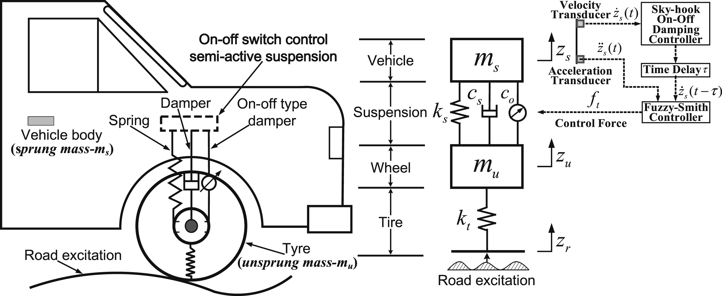
Fig.2
The relationship curve among c, c 0, and τ.
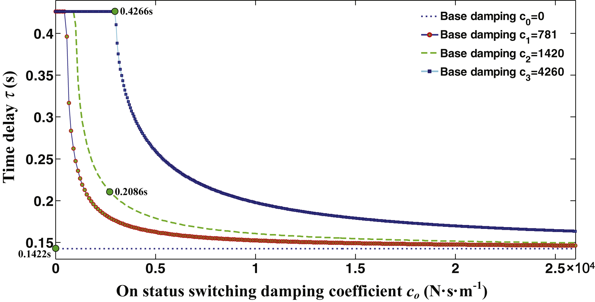
Fig.3
The stable area for full and non-full time delay with c s and c o .
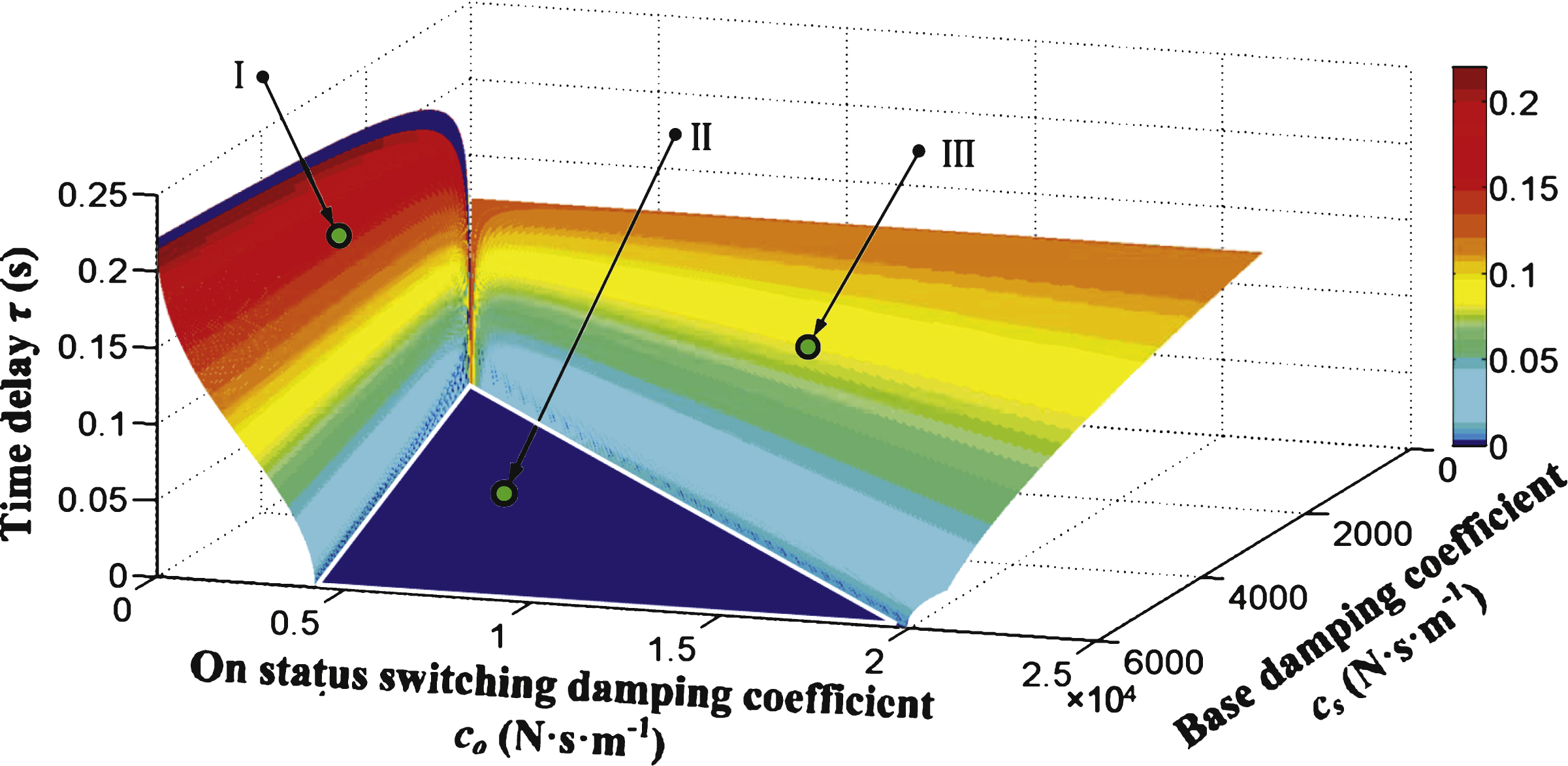
Fig.4
Acceleration amplitude frequency characteristic curve.
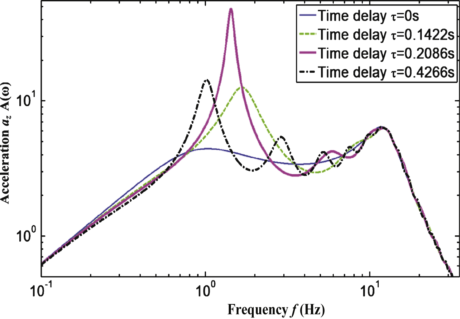
Fig.5
The dynamic load of tire amplitude frequency characteristic curve.
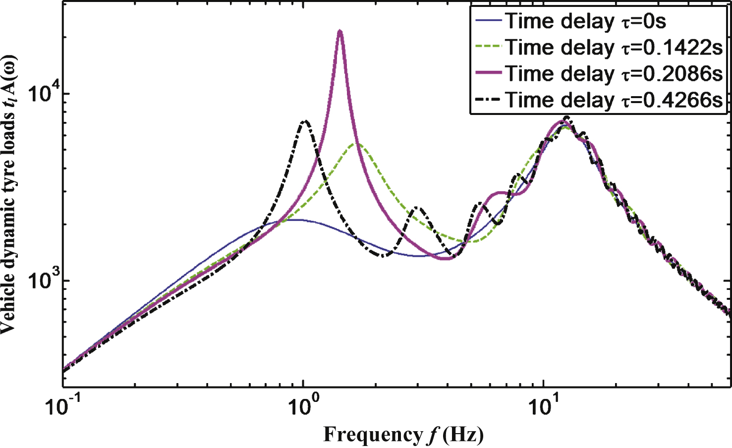
Fig.6
Block diagram of Smith predictive compensation control system with time delays.
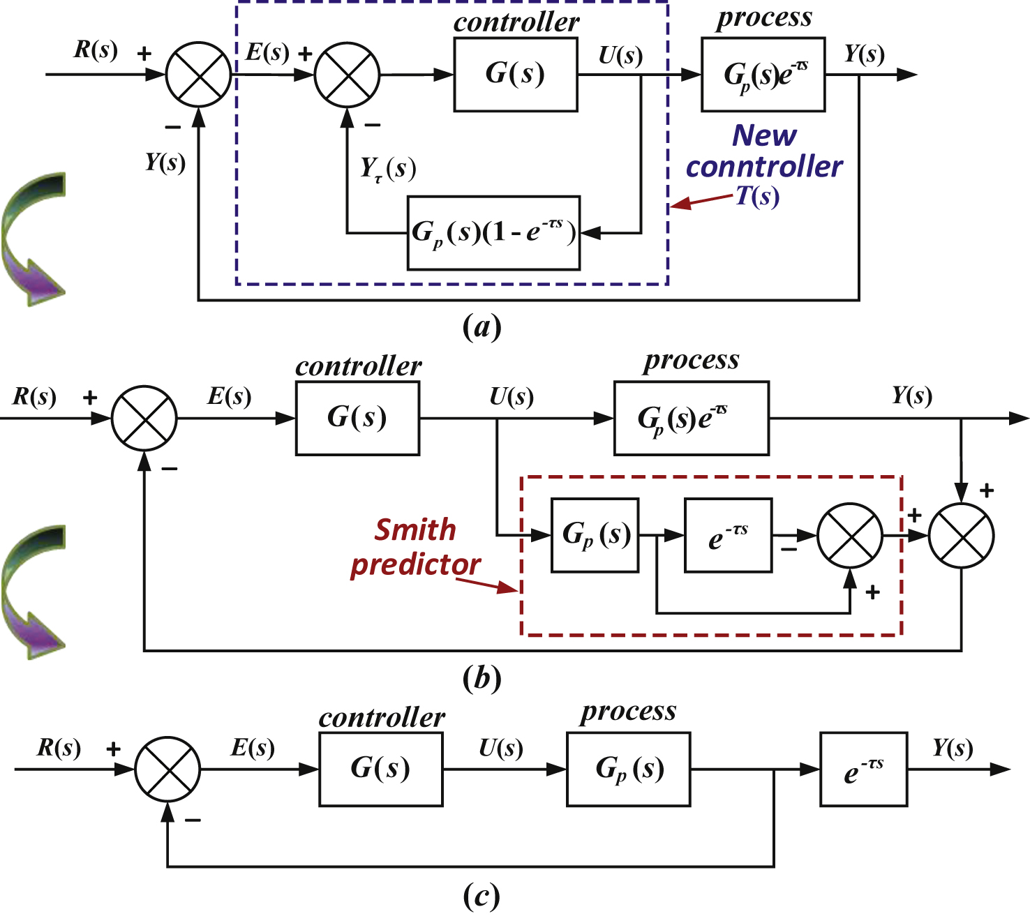
Fig.7
System structure of the Fuzzy-Smith predictive controller with time delay.
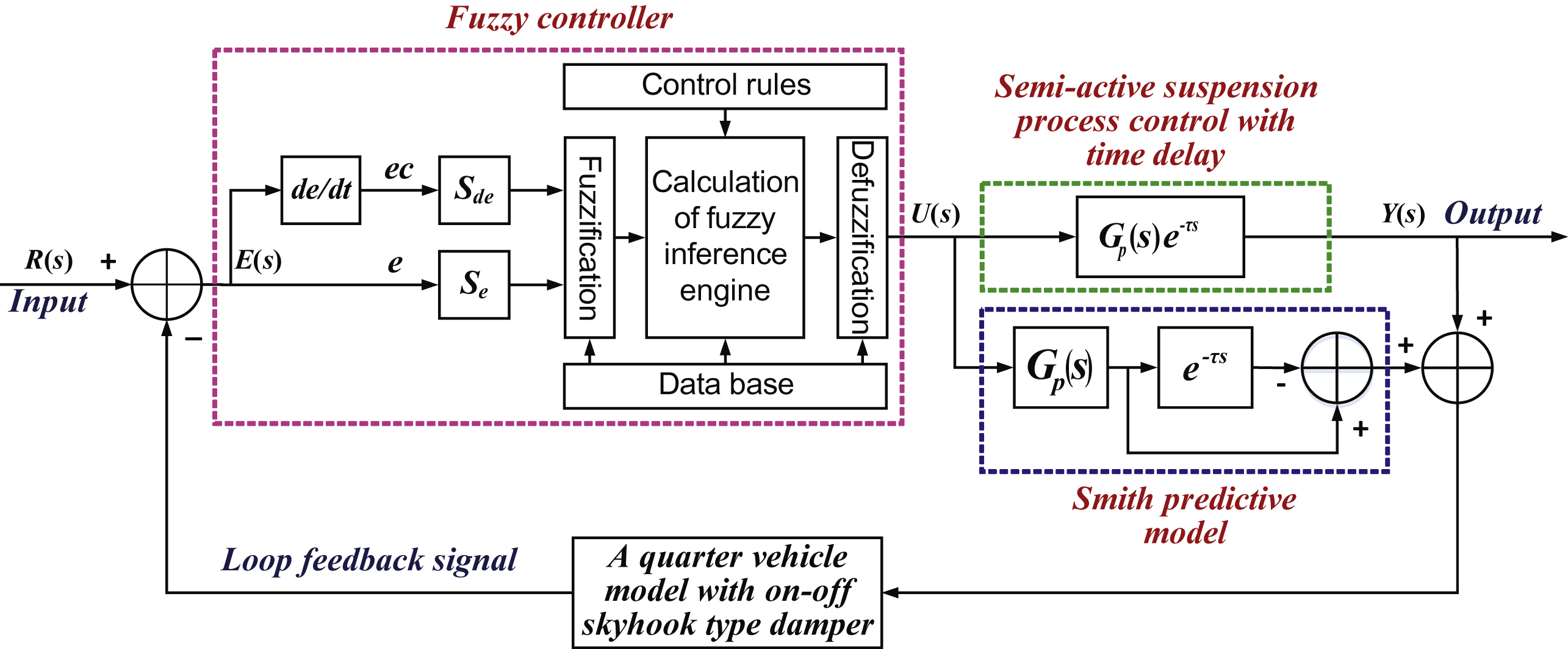
Fig.8
The road excitation used for simulation.
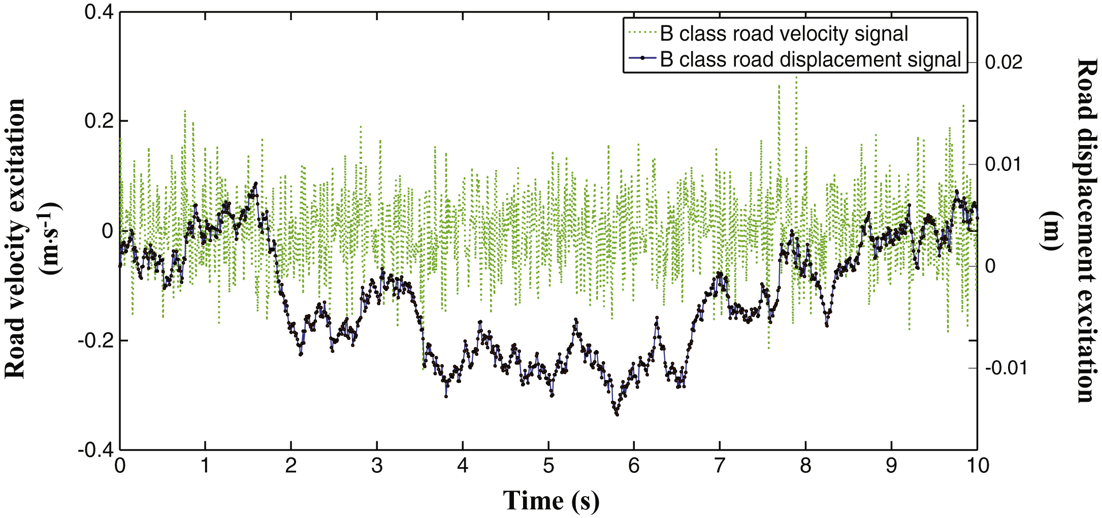
Fig.9
Simulation block diagrams of the Fuzzy-Smith time delays compensating system.
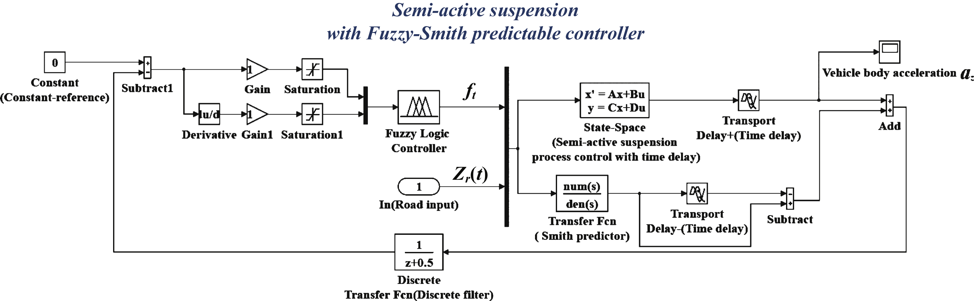
Fig.10
Simulation output of the vehicle body acceleration.
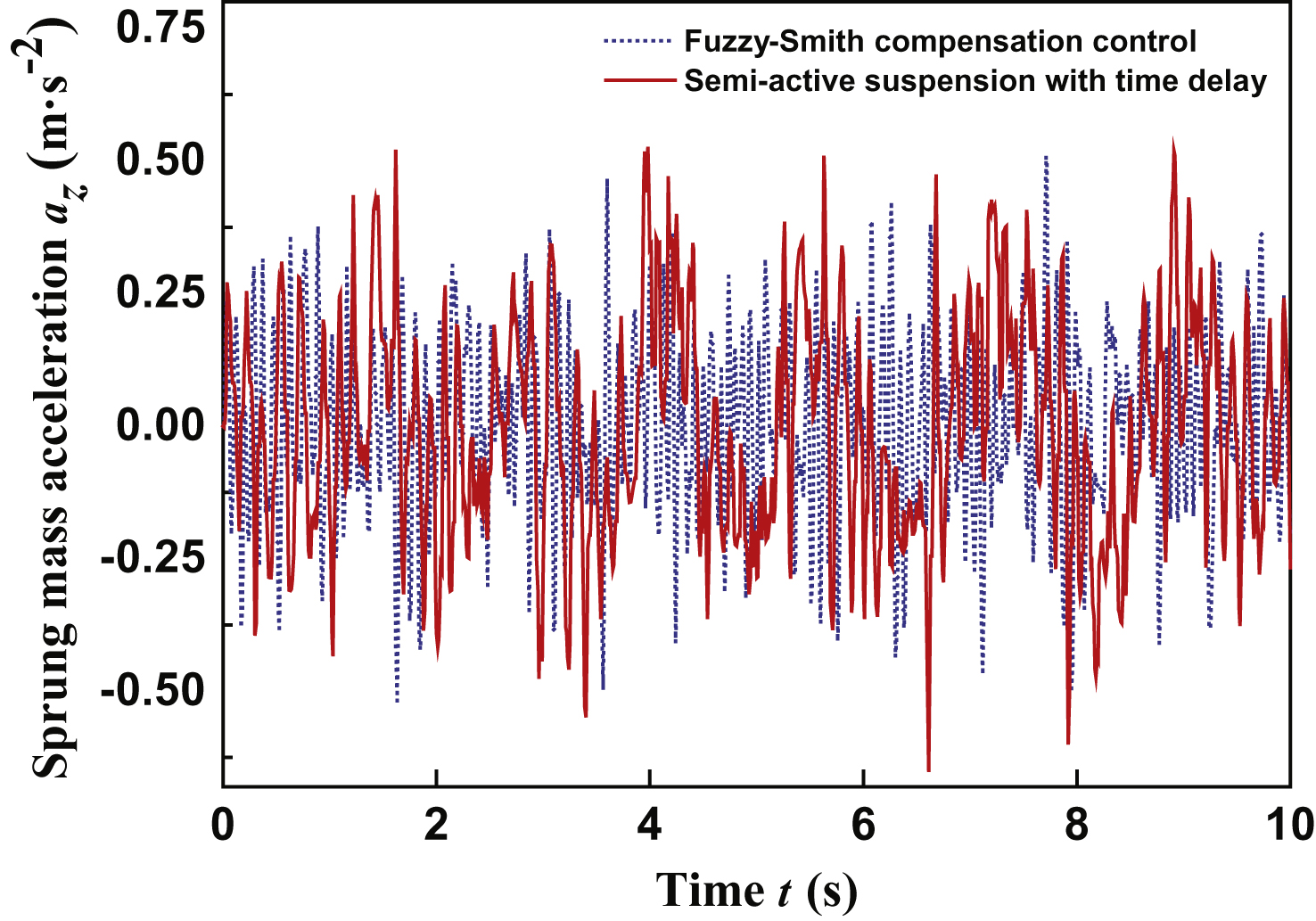
Fig.11
Simulation output of the vehicle suspension deflection.
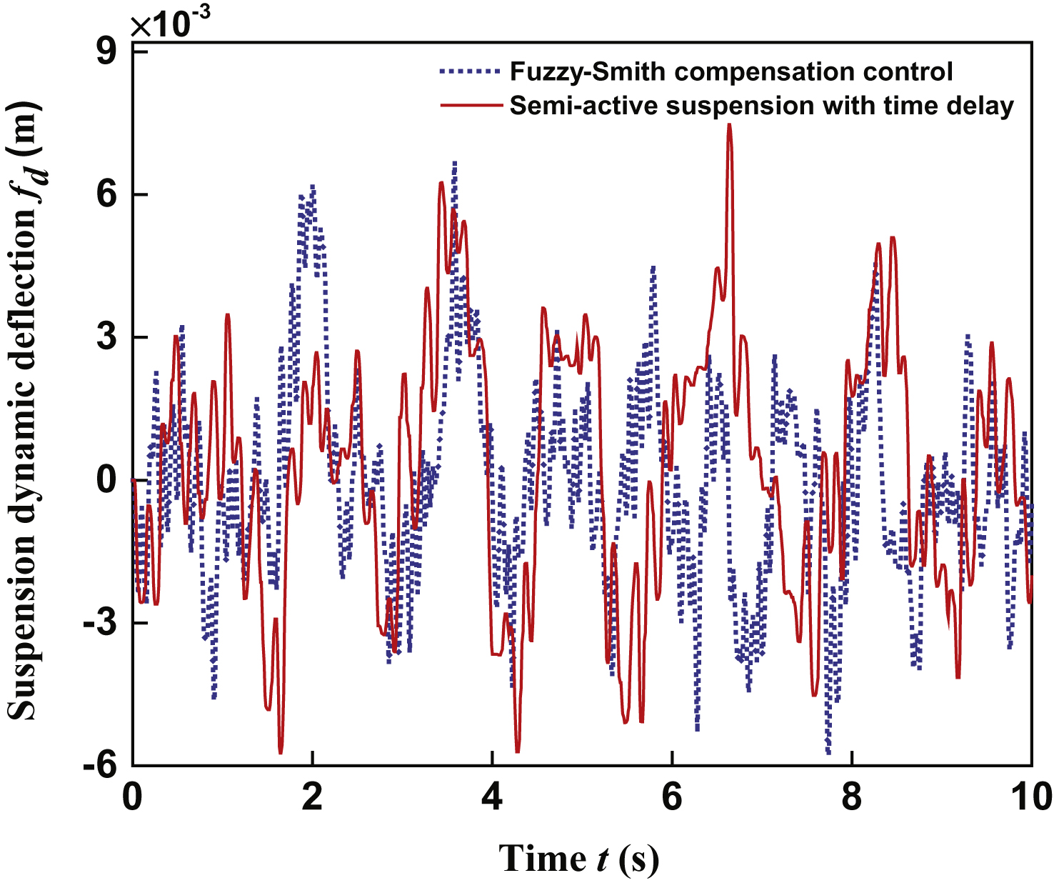
Fig.12
Simulation output of the vehicle tire dynamic load.
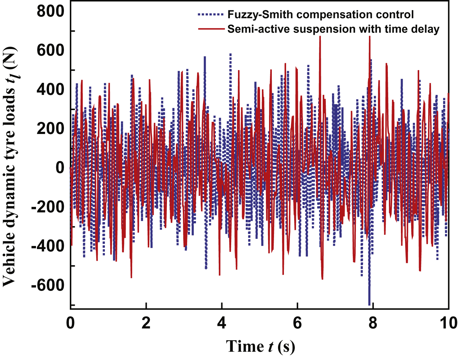
Fig.13
The schematic diagram of the experimental set-up.
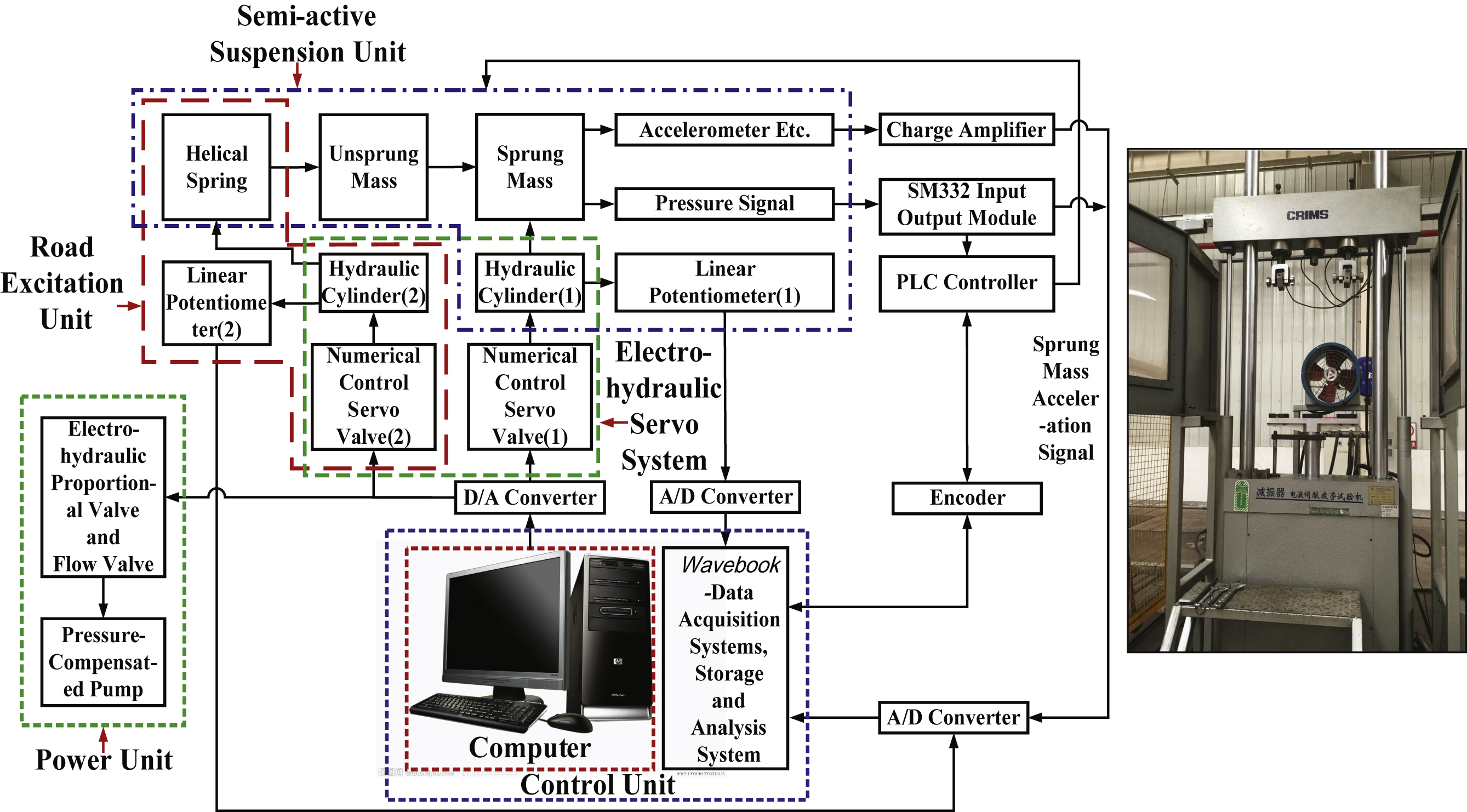
Fig.14
The test curves on vehicle body acceleration.
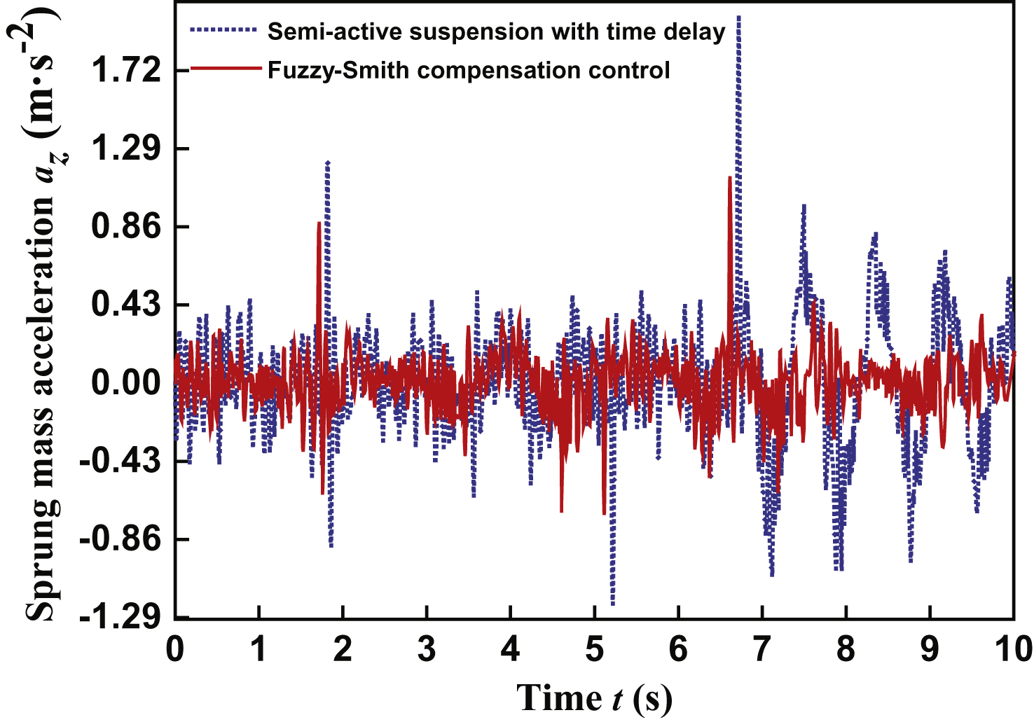
Fig.15
Output PSD curves of vehicle body acceleration.
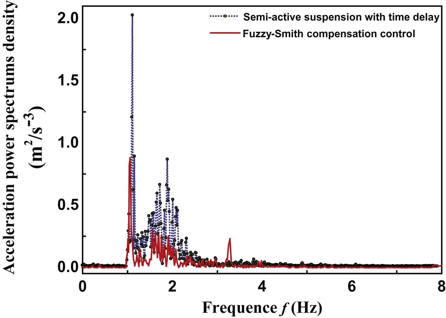
Table 1
Fuzzy control rule table (α 1 = 0.4, α 2 = 0.6)
| U | E | |||||||
| NB | NM | NS | ZO | PS | PM | PB | ||
| EC | NB | PB | PB | PM | PM | PM | PS | PS |
| NM | PB | PM | PM | PS | PS | PS | ZO | |
| NS | PM | PM | PS | PS | ZO | NS | NM | |
| ZO | PM | PS | PS | ZO | NS | NS | NM | |
| PS | PM | PS | ZO | NS | NS | NM | NM | |
| PM | ZO | NS | NS | NS | NM | NM | NB | |
| PB | NS | NS | NM | NM | NM | NB | NB | |
Table 2
Parameters of 2-DOF semi-active suspension system
| Parameter Name | Parameter Values |
| Sprung mass (m s ) | 492 kg |
| Unsprung mass (m u ) | 40kg |
| Tire stiffness (k t ) | 238145 N/m |
| Spring stiffness (k s ) | 16021 N/m |
| Base value damping coefficient (c s ) | 1420 N·s·m–1 |
| On status Switching damping coefficient (c o ) | 2800 N·s·m–1 |
Table 3
Comparison of test and simulation data
| Parameter Index | Simulation | Test | ||||
| Before | After | Improvement | Before | After | Improvement | |
| control | control | % | control | control | % | |
| Vibration acceleration of sprung mass (m/s2) | 0.209 | 0.1854 | 11.29 | 0.3167 | 0.2759 | 12.88 |
| Suspension stroke (m) | 0.0026 | 0.0021 | 19.23 | 0.0039 | 0.0035 | 10.26 |
| Dynamic load (N) | 231.97 | 194.34 | 16.22 | 345.91 | 286.69 | 17.12 |
| Acceleration power spectral density amplitude of sprung mass (m2/s3) | 0.1987 | 0.1773 | 10.77 | 0.2979 | 0.2672 | 10.30 |


