
Particle swarm optimization tuned fuzzy terminal sliding mode control for UPS inverters
Abstract
This paper proposes a particle swarm optimization algorithm tuned fuzzy terminal sliding mode control for the application of UPS inverters. Though classic sliding mode control (SMC) is insensitive to system uncertainties, it possesses an infinite system-state convergence time. For high-accuracy tracking control, a terminal sliding mode control (TSMC) is developed to provide a finite system-state convergence time. However, difficult estimation occurs in TSMC, and incurs high UPS inverter voltage harmonics and slow dynamic response. To obtain high-quality UPS inverter output voltage, a fuzzy logic (FL) with a computationally simple and practically easy estimator is integrated into TSMC to resolve system uncertainties. Simultaneously, the particle swarm optimization (PSO) algorithm is applied to optimally tune the control gains of the TSMC with a fuzzy estimator. Results indicate that the presented combination of PSO, FL and TSMC yields a closed-loop UPS inverter with good performance under various loading conditions. Simulation and experimental results indicate that the proposed control can achieve low total harmonic distortion (THD) under nonlinear loading conditions and fast dynamic response under transient loading conditions.
1Introduction
Uninterruptible power supply (UPS) has been widely applied to provide emergency power to critical loads including safe lighting, telecommunication centers and life support equipment in hospitals that cannot afford utility failures [2]. In UPS systems, the overall performance is dependent upon the static inverter-filter arrangement, which is used to convert DC voltage to a sinusoidal AC output. A primary concern of a UPS inverter is to determine an effective controller which is able to achieve accurate tracking of the desired sinewave command. Accurate tracking for a UPS inverter should meet the following requirements: 1) perfect sinusoidal voltage waveform, even under nonlinear loading; 2) fast transient response under sudden load changes; 3) a steady-state error of approximately zero. Owing to the simple structure and easy design, a PID control is typically used as the control method for the inverter. However, a PID controller cannot achieve satisfactory performance when the controlled plant experiences highly nonlinear loading [5, 6].Several control methods have been employed, such as H-infinity control, repetitive control, and multi-loop control, but they are difficult to realize, and their algorithms are extremely complex [4, 7, 11]. Sliding mode control (SMC) is intrinsically robust against system uncertainties [15]. The SMC has been presented as a good alternative for UPS inverter design, but a linear sliding surface is employed and the system trajectory has an infinite system-state convergence time [12, 13]. Recently, a terminal sliding mode control (TSMC) with a nonlinear sliding-surface has been developed and applied to many fields. Compared to linear sliding-surface-based control, the TSMC can force the system tracking error to converge to zero in finite time, and thus achieve a high-accuracy tracking control [9, 14]. This paper introduces such a control which possesses a finite system-state convergence time mechanism to overcome the disadvantages of classic SMC with an infinite system-state convergence time for special application to UPS inverters. However, the estimation of system uncertainties is a difficult problem in TSMC systems. Such problems will yield high THD, nonzero steady-state errors, and low dynamic responses in the terminal sliding mode controlled UPS inverter. Fuzzy logic (FL) controllers have been applied to a wide range of applications in various fields. FL has been further developed for power conversion applications, since its operation principle does not require precise knowledge of the load parameters [1, 3]. Hence, the estimation of system uncertainties can be accomplished by FL. The particle swarm optimization (PSO) algorithm is also an excellent evolutionary algorithm, and has been widely applied to many areas of science and engineering [8, 10]. To enhance the performance of UPS inverters, the PSO is used to optimally tune control gains of the TSMC with the fuzzy estimator. By combining PSO, FL, and TSMC, the presented system will easily achieve finite system-state convergence time, a zero steady-state error, fast dynamic response, and prevent a low THD under various loading conditions. Simulation and experimental results are presented to illustrate the good performance of the proposed controlled UPS inverter.
2Mathematical modeling of UPS inverter
As shown in Fig. 1, the output voltage v o of the UPS inverter can be forced to track a sinusoidal reference voltage, v d by applying the proposed control.
As shown in Fig. 1, two equations can be obtained by the use of the KVL and KCL:
(1)
(2)
Substituting Equations (1) into (2) yields thefollowing:
(3)
Let x
1 = v
o
,
(4)
Suppose the desired output voltage is x
d
= v
d
, and a state variable
(5)
Thus, the error state matrix can be obtained as
(6)
3Control design
For the sake of brevity, system (6) is redefined as follows:
(7)
The finite-time convergent sliding function is designed as follows:
(8)
From Equation (8):
(9)
Define
(10)
For system (6), the control law u can be expressed as follows:
(11)
(12)
(13)
While the system dynamics are in sliding action,s = 0:
(14)
Substituting Equations (14) into (13) yields the following:
(15)
Let
(16)
The condition for the existence of a sliding motion is,
(17)
The conditions φ i , ψ i and N to satisfy Equation (17) can next be obtained. Notice that w (t) in Equation (17) is an interference and in practice should be rewritten as w (k), where k denotes the sample interval. Because w (k) is generally uncertain, the control in this form cannot be implemented and must beestimated.
Therefore, define the uncertainty estimation error
(18)
Then, an algorithm is expressed as:
(19)
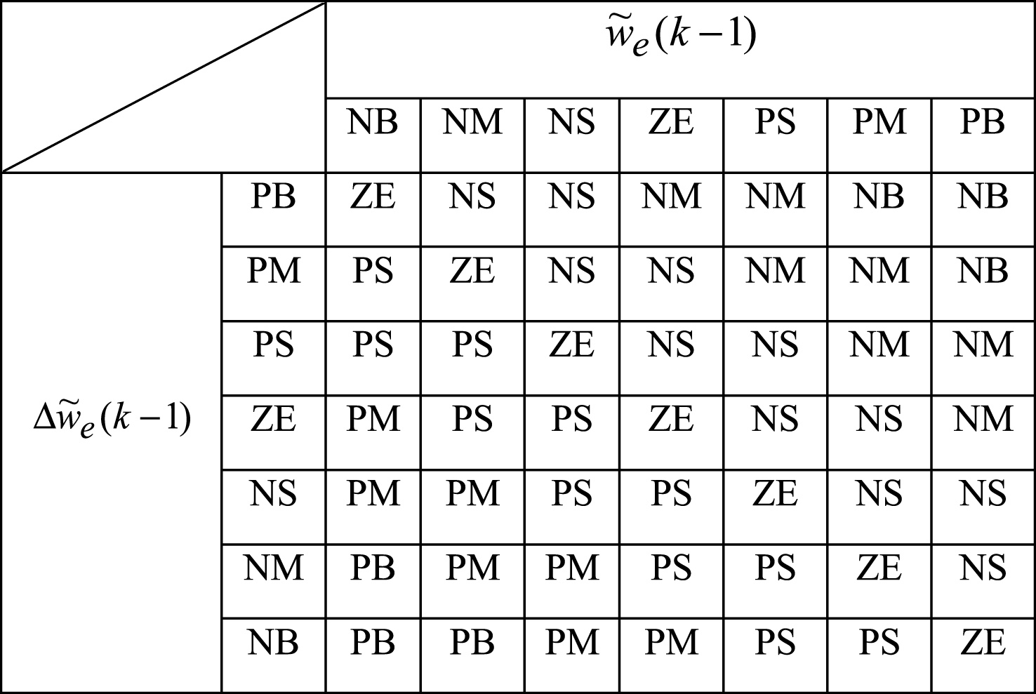
The FL is used to tune the β in Equation (19), and the fuzzy rule can be expressed as a two-input single-output system as follows:
(20)
The
The incremental change of
(21)
From Equations (18) through (21), when the parameter β is well tuned, the
Though the control gains can be tuned by the use of φ i , ψ i and N, thus achieving finite system-state convergence time, Equation (16) implies that the sine function across the surface s, and therefore chatter phenomenon, exists. Thus, to eliminate the chatter, the PSO algorithm represented in Equations (22) and (23) is used to optimally tune the control gains of the fuzzy TSMC. Equations (22) and (23) indicate the evolution models of a particle; then, the speed and position of each particle can be updated when moving toward a destination.
(22)
(23)
4Simulation and experimental results
The system parameters are listed as follows: DC source voltage, V DC = 220 V; switching frequency, f s = 18 kHz; output voltage and frequency, v o = 110 Vrms, f = 60 Hz; full resistive load, R = 12 Ω; diode bridge rectifier load (electrolytic capacitor: 200μF and load resistor: 55 Ω); filter inductor, L = 1.2 mH; filter capacitor, C = 10 μF. Figure 2(a) and (b) depict the simulated output voltage and the load current obtained using the proposed control and the classic SMC, respectively, under TRIAC load (from no load to full load) with a firing angle of 90° each half cycle. As shown by the figures, the proposed control indicates a smaller voltage drop and a fast recovery of the steady-state response (% THD of the output voltage equals 1.21%), as compared to the classic SMC (% THD of the output voltage equals 2.62%). The performance of the inverter with the proposed control under rectifier load is reported. Figure 2(c) indicates that the simulated output voltage waveform is nearly sinusoidal and has very small distortion (% THD of the output voltage equals 1.30%), which exceeds the industrial standard of 5% . Compared to the proposed control, the simulatedwaveforms obtained using the classic SMC under a rectifier load, are reported in Fig. 2(d), with a % THD of 5.66% ; note that the output voltage distortion is high. Additionally, experimental waveforms under TRIAC load are investigated. Figure 3(a) shows the experimental waveform with the proposed control under TRIAC load (from no load to full load) with a firing angle of 90° each half cycle. Figure 3(b) shows the experimental waveform with the classic SMC under the same load condition. Results indicate that the proposed control provides better compensation of output voltage waveform (i.e., a smaller voltage drop and faster recovery time), particularly at the firing angle (% THD of the output voltage equals 1.28%), as compared to the classic SMC (% THD of the output voltage equals 2.94%). Figure 3(c) and (d) show the experimental output voltage and the load current waveforms of the UPS inverter controlled by the proposed control and the classic SMC under rectifier load, consisting of a full wave rectified with a parallel resistor and capacitor filter. As shown in Fig. 3(c), only a slight distortion (% THD of the output voltage equals 1.36%) occurs in the output voltage when the current rises abruptly. In contrast to the proposed control, the experimental output-voltage waveform obtained using the classic SMC exhibits a high % THD of 5.87% . Indeed, the proposed control decreases the high THD, reduces the steady-state error, and quickly converges to the origin.
5Conclusions
By combining PSO, FL, and TSMC, the presented system has improved the steady-state and dynamic response of the UPS inverter. The TSMC can resolve the classic SMC problem, but the difficult estimation of system uncertainties still exists in TSMC. Such difficulty may cause high voltage harmonics, and slow transient response. The PSO algorithm is used to optimally tune the control gains of the fuzzy TSMC, thus obtaining robust UPS inverter performance. Simulation and experimental results show that THD and dynamic response results from a UPS inverter under the proposed system exceed the results achieved under the classic SMC system with both linear and nonlinear loading.
Acknowledgments
This work was supported by the Ministry of Science and Technology of Taiwan, R.O.C., under contract number MOST104-2221-E-214-011.
References
1 | Chikh A, Chandra A (2015) An optimal maximum power point tracking algorithm for PV systems with climatic parameters estimation IEEE Trans on Sustainable Energy 6: 2 644 652 |
2 | Wilamowski BM, Irwin JD (2011) Power electronics and motor drives CRC Press Boca Raton, FL, USA |
3 | Radim B, George JK (2011) Concepts and fuzzy logic Cambridge, Massachusetts, London, England MIT Press |
4 | Zhang B, Zhou KL, Wang DW (2014) Multirate repetitive control for PWM DC/AC converters IEEE Trans on Industrial Electronics 61: 6 2883 2890 |
5 | Shin HB, Park JG (2012) Anti-windup PID controller With integral state predictor for variable-Speed motor drives IEEE Trans on Industrial Electronics 59: 3 1509 1516 |
6 | Rasoanarivo I, Sargos F (2013) Multi-objective analysis for designing and controlling micro-grids under multi-control with PID, MHCC and FOPID controllers Proc IEEE Int Conf Industry Applications Society Annual Meeting 1 8 |
7 | He J, Li YW (2012) Generalized closed-loop control schemes with embedded virtual impedances for voltage source converters with LC or LCL filters IEEE Trans on Power Electronics 27: 4 1850 1861 |
8 | Parsopoulos KE, Vrahatis MN (2010) Particle swarm optimization and intelligence: Advances and applications, information science reference Hershey, PA, USA |
9 | Lu KF, Xia YQ (2013) Finite-time fault-tolerant control for rigid spacecraft with actuator saturations IET Proceedings-Control Theory and Applications 7: 11 1529 1539 |
10 | Ishaque K, Salam Z (2013) A deterministic particle swarm optimization maximum power point tracker for photovoltaic system under partial shading condition IEEE Trans on Industrial Electronics 60: 8 3195 3206 |
11 | Howlader M, Urasaki N, Yona A, Senjyu T, Saber AY (2013) Design and implement a digital H-infinty robust controller for a MW-class PMSG-based grid-interactive wind energy conversion system Energies 6: 2084 2109 |
12 | Sanchis P, Ursaea A, Gubia E, Marroyo L (2005) Boost DC-AC inverter: A new control strategy IEEE Trans on Power Electronics 20: 2 343 353 |
13 | Aghatehrani R, Kavasseri R (2013) Sensitivity-analysis-based sliding mode control for voltage regulation in microgrids IEEE Trans on Sustainable Energy 4: 1 50 57 |
14 | Li SH, Zhou MM, Yu XH (2013) Design and implementation of terminal sliding mode control method for PMSM speed regulation system IEEE Trans on Industrial Informatics 9: 4 1879 1891 |
15 | Shtessel Y, Edwards C, Fridman L, Levant A (2014) Sliding mode control and observation Springer New York |
Figures and Tables
Fig.1
Digitally controlled UPS inverter.
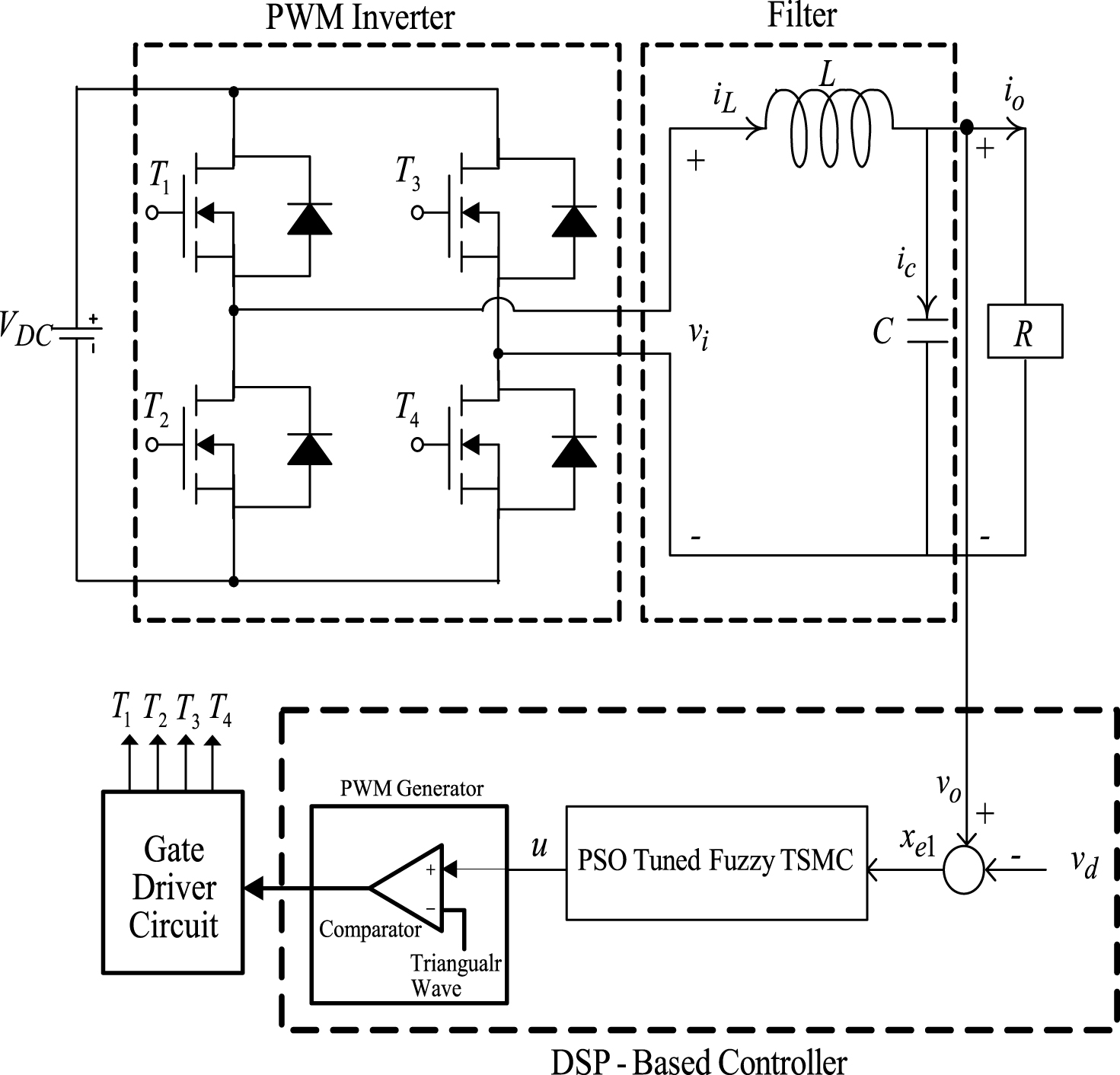
Fig.2
Simulated waveforms of output voltage and the load current under (a) TRIAC load with the proposed control; (b) TRIAC load with classic SMC; (c) rectifier load with the proposed control; (d) rectifier load with classic SMC.
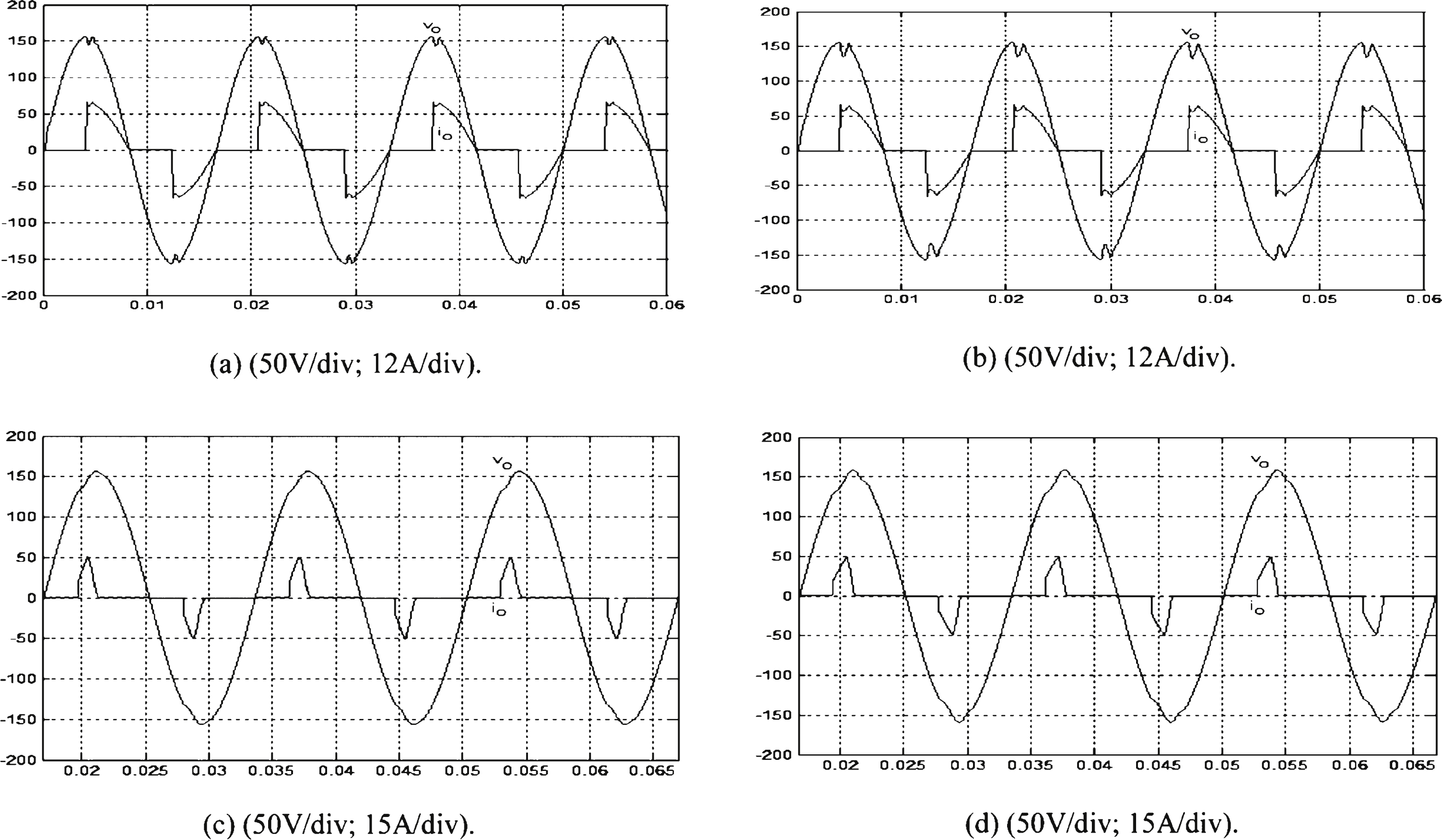
Fig.3
Experimental waveforms of the output voltage and the load current under (a) TRIAC load with the proposed control. (b) TRIAC load with the classic SMC. (c) Rectifier load with the proposed control. (d) Rectifier load with the classic SMC.
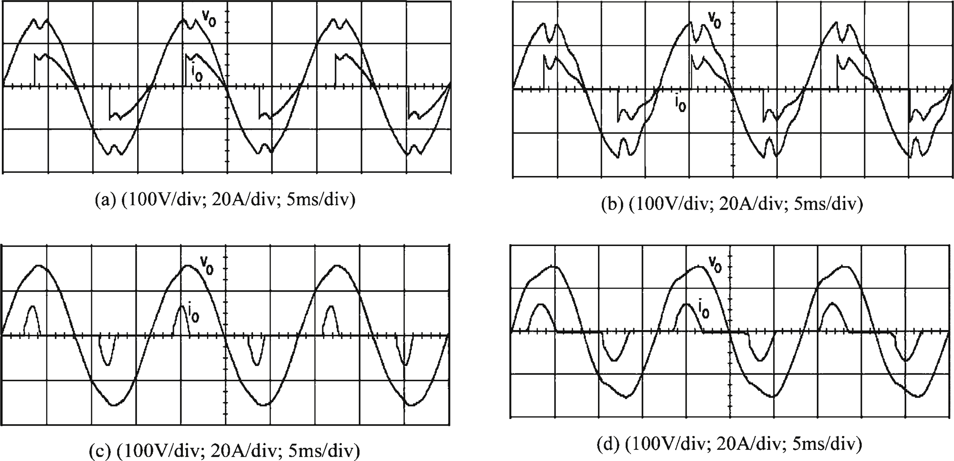
Table 1
Fuzzy rule base
 |


