
Application of intelligent virtual reality technology in Clothing virtual wear and color saturation after COVID-19 epidemic situation
Abstract
The COVID-19 epidemic has brought a huge impact to the clothing industry. Because of the inconveniences caused by countermeasures, clothing consumers can’t go to physical stores to try on, so it is urgent to develop a virtual clothing trial system. In addition, online fitting and online shopping gradually become the trend of clothing consumption. Based on virtual reality technology, this paper proposes a virtual clothing fitting system, and studies the color saturation in the process. In this paper, a method of parametric drawing of garment characteristic curve is proposed, and the shape of garment is designed by using control vertices. Based on this, this paper presents four forms of sutured parabola space and their control point solving algorithm. According to the principle of scale method, a three-dimensional coordinate transformation model of feature points is established. The model can calculate the coordinates of each characteristic value point of clothing according to the body shape information provided by customers and the empirical formula of different clothing styles, and then reverse calculate the curve control point. Furthermore, Bezier surface generation method is used to fit the control points. After the surface patches are spliced, the 3D rigid clothing model can be obtained. Experiments show that the method of personalized clothing modeling in this paper is efficient and accurate, which can be further extended to the observation system with larger degree of freedom.
1Introduction
A novel corona virus pneumonia is a novel corona virus infection caused by 2019 new type of pneumonia [1]. The outbreak of covid-19 has brought great impact on the industrial economy. The new crown epidemic has a great impact on the offline retail of the textile and garment industry in the short term. The loss of clothing retail is net loss, because the depreciation rate of clothing inventory is very high. Clothing retail is most afraid of high inventory, low turnover, especially fashion. On the one hand, the peak stage of epidemic fermentation is in the Spring Festival sales season, and the proportion of clothing, gold jewelry, etc. in the first quarter during the Spring Festival is relatively high (in January February 2019, clothing, gold jewelry retail accounted for 18% and 19% of the whole year respectively) [2–4]. On the other hand, if the negative impact of the epidemic on the economy exceeds expectations, it may cause a long-term drag on the demand of the industry [5–11].
Under the influence of the epidemic, we need to develop a virtual clothing trial system to stimulate clothing consumption. 3D clothing trial system is a direction of virtual reality and one of the important subjects of online shopping. Clothing sales account for a very large proportion of commercial trade, and its sales have particularity, which requires customers to participate in and experience. In the process of virtual fitting, the participation and authenticity of human activities is an important part of users’ immersion [12]. The realization of clothing personalized modeling and drape of materials similar to cloth are the difficulties that are generally concerned by the international community. Solving these problems will provide a good foundation for online e-commerce.
In this paper, a method of parametric drawing of garment characteristic curve is proposed and the shape of garment is designed by using control vertices. Based on this, this paper presents four forms of sutured parabola space and their control point solving algorithm. Furthermore, Bezier surface generation method is used to fit the control points. After the surface patches are spliced, the 3D rigid clothing model can be obtained. It is of great reference value to the development of clothing trial system.
2Fitting of garment curved surface and analysis of dress simulation
The design of 3D clothing virtual fitting system enables users to see the 3D clothing synthesized according to their own size on the computer screen, just like they try on it by themselves [13]. Therefore, the three-dimensional clothing virtual fitting system should first reflect the real body shape of the wearer, and then on this basis, three-dimensional clothing, using the three-dimensional clothing effect simulation technology, to show the overall effect of clothing. Theoretically, the more control parts of the human body, the more practical the clothing to try on. However, too many control parts will inevitably increase the difficulty in the mathematical processing of the clothing model, and it is unnecessary.
The data from anthropometry is only point data with scalar property [14]. These scalars only have the concept of length and width, but have no shape information. How to convert these scalar values into 3D clothing data. This is the first problem to be considered in the development of 3D clothing model. According to the size table of different body type input by the user, the sizes of each control part of the garment are generated.
Combining the two-dimensional line modeling with the three-dimensional body modeling, the three-dimensional coordinate transformation model is used to construct the garment feature surface. Its advantage is that it can simplify the model and make it easy to study. The human body is a complex curved body, which is difficult to grasp in the geometric characteristics, and the human body shape is different [15–17]. Because this topic focuses on the performance of the effect after the customer’s fitting, and does not emphasize the very detailed human body shape performance of the customer, this topic simplifies the three-dimensional information needed for the selection of three-dimensional clothing modeling, so that the number of curved surface and curve shape to be analyzed becomes less [18]. This kind of geometric model can not only ensure the correct size of the main parts of clothing, but also ensure that the size of other parts has no big difference. The three-dimensional clothing model generated from geometric feature information needs to calculate the geometric feature size of human body, including height, shoulder width, chest circumference, waist circumference, hip circumference, etc. to generate clothing surface points. Then, the control points needed to generate Bezier surface avoid the unstable results of different complex surfaces in other surface modeling methods, so as to improve the speed of surface construction [19–21].
(1) Data collection and processing of 3D clothing model
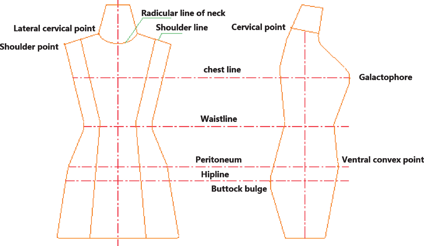
Before measurement, measurement planning should be done well, that is, division of measurement area and selection of measurement points. The relevant theories of interpolation and reverse engineering show that in order to interpolate the point cloud model of the model through a certain number of data points on the model, it is necessary to ensure that the basic data collected can reflect the characteristics of the model surface and the basic shape characteristics of the model. It cannot be too much, otherwise it will affect the smoothness and roundness of the fitted surface; it cannot be too little, otherwise it cannot accurately reconstruct the shape characteristics of the measured model. In each measurement area, the number of measurement points should be determined according to the curvature change of the surface. For the area with larger curvature change, the measurement points should be closer; for the area with smaller curvature change, the measurement points should be thinner. In this way, it can ensure that the curvature of each measurement area does not change much, and avoid unnecessary crash caused by measurement. Based on the above principles, six datum points and six datum lines are determined on the human body surface for the convenience of measurement and the need of dimension control, as shown in Fig. 1.
Fig. 1
Datum point and datum line map of human body surface.
(2) Fitting of garment characteristic curve
By using the control vertex to design the shape, the curve constructed by the control vertex can easily meet the mathematical characteristics required by the fitting display, and can ensure the continuity of the first-order or higher-order derivative at the joint of the curve and surface. In this paper, the curvilinear surface is used to draw the clothing surface, and the intersection of the human body main line and the cross section of the side neck point is taken as the coordinate origin, thus the rectangular coordinate system is established. Then select the appropriate point of view, establish the observation coordinate system, through the perspective projection transformation, get the three-dimensional clothing model on the two-dimensional computer screen. In order to ensure the accuracy of fitting, we can use the size table of the human body model, the sample points of the model and the data points obtained from the fitting curve of the above feature parts to reverse the control points, and then use the curve to fit the obtained control points. In the specific modeling process, the clothing is divided into several curves, and then the method of classical mathematics is used to fit the segmented characteristic curve, assisted by other modeling curves, and the three-dimensional rigid clothing model is constructed together with the characteristic curve.
3Construction method of bezier surface
The method of constructing interpolating curves and surfaces is mainly used to construct those curves and surfaces that pass through given fixed value points, but not suitable for the design of curves or surfaces. The Bezier curve is based on the design requirements, using some approximation method, rather than the traditional interpolation method. This method is faster than NURBS and B-spline method in constructing surface.
3.1Bezier curve construction method
A n-th curve can be expressed as:
(1)
Where Vi (i = 0,1,...,n) is the given polygon vertex and rewrites the expression of the n-th degree curve, the following formula can be obtained:
(2)
Where Vi is the vertex of the feature polygon and
(3)
A very useful property of Bezier curves is that they always pass through the first and last control points. That is to say, the boundary condition of the curve at two ends is: P(0) = V0, P(1) = Vn. The first derivative of Bezier curve at the end point can be calculated by the coordinates of the control point:
(4)
That is, the tangent of the curve at the starting point falls on the line of the first two control points, and the tangent of the curve at the end falls on the line of the last two control points. Similarly, the second derivative of Bessel curve at the end point can be calculated as:
(5)
Where n is the power of Bessel curve. Generally, the r-order vector at the V0 point is:
(6)
That is, P’(0) is only related to (r + 1) vertices such as V0, V1, V2,. . . , Vr, and the s-order vector at the end Vn is:
(7)
Another important property of Bezier curve is convex hull, that is, Bezier curve is completely contained in the convex hull formed by characteristic polygon. These points are given by Bessel mixed function, whose values are all positive and the sum is 1.
Therefore, any curve position is only the weighted sum of the control point position. The convex hull property of Bezier curve ensures that the polynomial moves forward with the balance of control points without oscillation. Other properties include symmetry and geometric invariance. Symmetry means that given the feature multilateral form V0, V1, V2,. . . , Vn, the Bezier curve can be constructed from V0 or from Vn in reverse. The shape of the two curves is identical, but the parametric direction is opposite. The symmetry of the curve shows that the Bezier curve defined by the same feature polygon is unique. The meaning of geometric invariance is that the shape of Bezier curve only depends on the vertex Vi (i = 0,1,...,n) of the feature polygon, and has nothing to do with the selection of coordinate system.
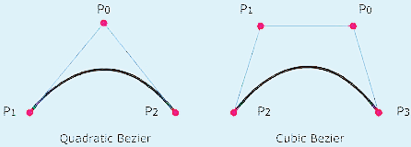
3.2Quadratic bezier surface
In the three-dimensional clothing model program of this paper, the quadratic Bezier function in the open GL graphics software package is used, which not only brings convenience in design, but also avoids the increase of calculation due to higher-order polynomials. The quadratic Bezier curve is generated by three control points. By substituting n = 2 into the Formula, three mixed functions of the quadratic Bessel curve are obtained as follows:
The form of the mixed function determines how the control point affects the shape of the curve. At this time, the value of the parameter u ranges from 0 to 1. When u = 0, the non-zero mixed function is B0,2 and its value is 1. When u = 1, the nonzero mixed function is B2,2, and the value at this point is 1. In this way, the quadratic Bezier curve always passes through the control points V0 and V2. The function B1,2 affects the curve shape when the parameter u is taken as the middle value, so the generated curve is close to V1. When u = 1/2, the mixed function B1,2 takes the maximum value. It should be noted that each mixed function is not 0 in the whole value range of parameter u. In this way, it is impossible to control the shape of Bezier curve locally. If you change the position of any control point, the entire curve will be affected.
At the end of the quadratic Bezier curve, the first derivative is:
The second derivative is:
By using derivative expression, a continuous segmented curve can be constructed between two curve segments. If the mixed function is described as a polynomial expression, the quadratic Bessel curve function can be written in matrix form:
(8)
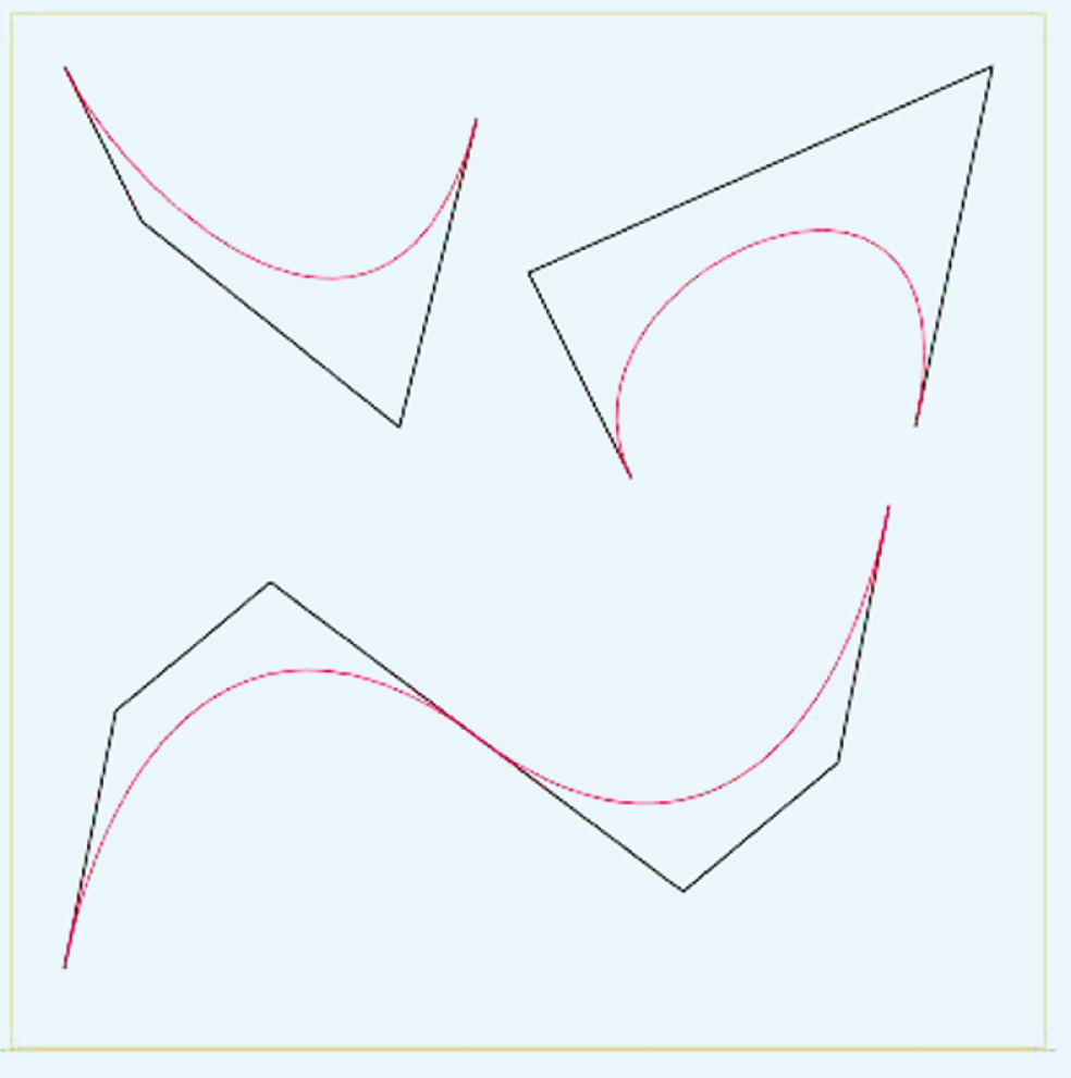
3.3Mosaic of bezier surface
In the design of complex human body curve, segmentation technology is used. When two Bezier curves are spliced, the specified continuity requirements shall be met at the connection point. If only the first and second order are required to be continuous, it can be easily realized by graphical method, as shown in Fig. 2:
Fig. 2
Mosaic of Bezier curve.
P(u) and Q(w) is noted as two Bezier curves, P(u) is defined by P0, P1, P2,. . . , Pm, and Q(w) is defined by Q0, Q1, Q2,. . . , Qm, Pm = Q0, as shown in the Fig. 3. P(u) and Q(w) is noted as:
Fig. 3
Graphic representation of second order continuity.
(9)
(1) First order continuity between two curves
From Formula (4), the first-order leading vector of curve P(u) at the end Pm is:
(10)
The first-order leading vector of curve Q(w) at the end Q0 is:
(11)
When the curve P(u) and Q(w) are spliced, they must have the same tangent direction at the joint, that is to say, the following conditions shall be met:
(12)
Where λ is a constant. Combine the above formula to get:
Rewrite it to:
(13)
In the formula, p = Pm = Q0, q = Pm-Pm - 1,λ, m and n are all normal numbers. The geometric meaning of formula (13) is that when two Bessel curves are spliced, in order to make them reach the first-order continuous vertex Pm - 1, Pm = (Q0) and Q1 must be col-linear.
(2) Meeting the requirements of second-order continuity between two curves
The second-order leading vectors of curves P(u) and Q(w) at the joint are p′′(1) and Q′′(0).
From Formula (5):
(14)
(15)
When two curves are required to be second-order continuous at the joint, the relation expressed in Formula (16) must be satisfied, where μ is a positive constant.
(16)
If curvature continuity is required, there are:
(17)
The necessary condition for two Bezier curves to achieve curvature continuity is μ =λ2 when the above Formula is expanded and simplified. Substituting Formula (17) into Formula (13) and expanding it, we can get:
(18)
Formulas (13) and (18) are the conditions of first and second order continuity when two Bezier curves are spliced. If the power of the two curves is the same and the tangent modulus at the joint is the same, then the formulas (13) and (18) can be simplified as follows:
The diagram is as shown in Fig. 3
A Bezier curve segment can fit any number of control points. The curve will approach these control points, and the relative position of the control points determines the degree of Bezier polynomials. Like interpolating splines, Bezier curve motion can have given boundary conditions and given characteristic matrix. Bezier method is a milestone in curve and surface modeling, which is based on approximation principle. By using Bezier method, the mathematical curve can be easily approximated and the curve shape of clothing can be perfectly presented.
43D coordinate transformation model of feature points
When using Bezier surface method to construct rigid clothing model, clothing is divided into regular pieces. To get each piece of clothing surface, these surfaces are spliced together to form a three-dimensional clothing. Each piece of clothing surface is obtained by fitting and approaching the control points on the surface. Therefore, in order to generate Bezier surface, it is necessary to find the 3D coordinate values of these control points.
Through a large number of research, this paper studies a method to generate the key value points needed for drawing 3D garment surface based on the size of key parts of human body. In this method, the data points obtained from the size table of the human body model, the sample points of the model and the fitting curves of the above feature parts are used to reverse calculate the control points, and then the curve is used to fit the obtained control points. The scale method is based on a complete set of theoretical formulas, which use numerical methods to express the scale relationship between each coordinate point of clothing and several key parts of human body. By using these formulas, we can determine all the type value points needed for clothing drawing, and then according to different requirements, we can use straight lines or curves to connect these type value points in turn to get the clothing we need. The 3D coordinate transformation model of this system is designed based on the scale method.
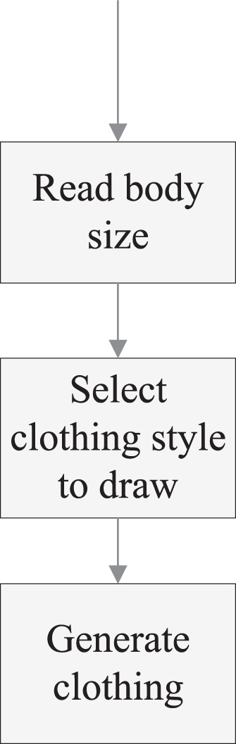
4.1Method of parametric drawing 3D clothing
The function flow of the parametric clothing drawing system is to read the user’s body size from the database according to the user’s login user name, and then select the clothing style to try on. The system will automatically generate a three-dimensional rigid clothing model, which can be simply represented by the UML activity diagram in Fig. 4.
Fig. 4
Setting for document template.
Among them, each group of human body size corresponds to a user in the system. In this paper, we draw clothes based on the basic dimensions of 160 / 84A women’s standard body shown in Table 1.
Table 1
160 / 84A Women’s Standard Body Size Table (Unit: cm)
| Position | Neck circumference | Total shoulder width | Bust | Dorsal length | Waist | Hipline | Buttock length |
| (N) | (S) | (B) | (BL) | (W) | (H) | (HL) | |
| Size | 33.6 | 39.4 | 87 | 34 | 68 | 90 | 18.4 |
According to the principle of scale method, the coordinates of each characteristic value point in each garment can be calculated and determined according to the empirical formula of different garment styles by the seven control sizes in Table 1. Then, according to certain rules, the coordinates of modeling points connecting the curves of each type value point are obtained. Then, according to the coordinate of the characteristic points on the curve and the space analytic geometry algorithm, the curve control points are calculated. Combined with Bezier surface generation method, the parameterized three-dimensional garment pieces can be obtained. Then, the whole garment model can be drawn by joining the curved surface and making the princess line symmetrical. Among them, the characteristic value points refer to the representative points which have great influence on the body shape or clothing shape, such as breast convex point, abdomen convex point, shoulder point, side neck point, etc. The system can establish drawing rules for multiple styles, and each set of drawing rules corresponds to a set of fixed empirical formula. Users only need to select a desired style, and then the system can generate the clothing model according to the user’s choice and the specific rule base
4.2Drawing garment pattern with scale method
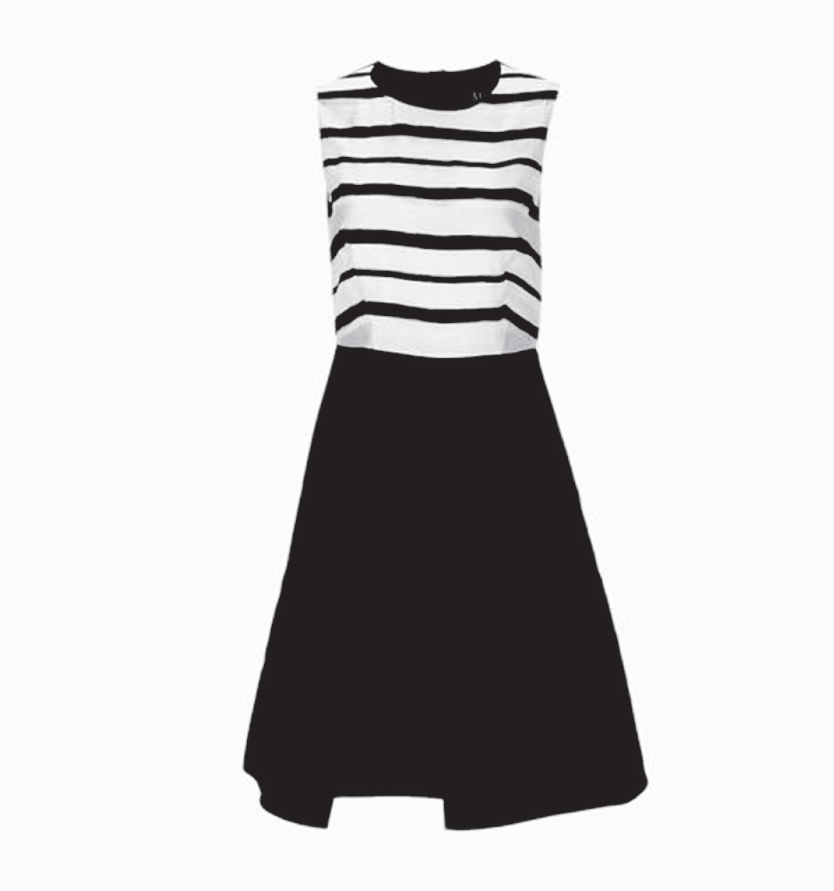
Through a large number of research on clothing manufacturers, this paper designs a set of rules for the proportion of different styles of clothing. Here we choose a simple style women’s sleeveless dress as a demonstration. Using the user’s body size given in Table 1, we can use the proportion method to make the model of women’s sleeveless dress as shown in Fig. 5.
Fig. 5
Model of women’s sleeveless dress.
The garment drawing formula determines the appearance of the garment, represents the general rule of the change of the garment structure, and reflects the relevant factors affecting the garment parts. Because clothing is three-dimensional, it is not only one factor that affects its change. However, in order to study the changing law of clothing, we must eliminate the interference and grasp some leading factors, so as to ensure the accuracy and rationality of the formula to the maximum extent.
For example, “armhole depth” is a special part, it is not as intuitive as “bust", “back width” and other parts that can be directly measured. The formula of this part is based on the general measurement results, combined with the proportion of visual beauty. There are many factors that affect the armhole depth, but only “bust” and “height” are the main factors, such as “fabric thickness", “shoulder angle” and other important interference factors can be ignored.
In the traditional drawing process, some linear formulas with correction value are often used in the “armhole depth” part. We adopt the form of (B/5 + 3), which is generally accepted and widely used by people. The unit of constant term in the formula is cm. It has been proved that the following formula can be used in general normal body shape, and the result is relatively ideal, which is also close to the real measurement value of aesthetic effect. Table 2 gives the calculation formula of each part of women’s sleeveless dress.
Table 2
Calculation formula of each part of clothing
| Part name | Calculation formula | Part name | Calculation formula |
| Skirt length | BL + HL + 18 | armhole | B/5 + 3 |
| Waistline position | BL | Hip line position | Under waistline HL |
| Front collar width | N/5 + 2.4 | Back neck width | N/5 + 3.4 |
| Front collar depth | B/5 + 3-4 | Deep back collar | 3 |
| Anterior shoulder obliquity | 6/15 | Posterior shoulder obliquity | 5/15 |
| Front shoulder width | S/2-0.3 | Back shoulder width | S/2 |
| Anterior bust | B/4 + 0.5 | Posterior bust | B/4-0.5 |
| Front waistline | W/4 + 0.5 + front saving | Back waistline | W/4-0.5 + front saving |
| Front hip circumference | H/4 + 0.5 | Posterior hip circumference | H/4-0.5 |
| Front skirt | H/4 + 0.5 + 3 | Back skirt | H/4-0.5 + 3 |
| Bottom swing up | 1 |
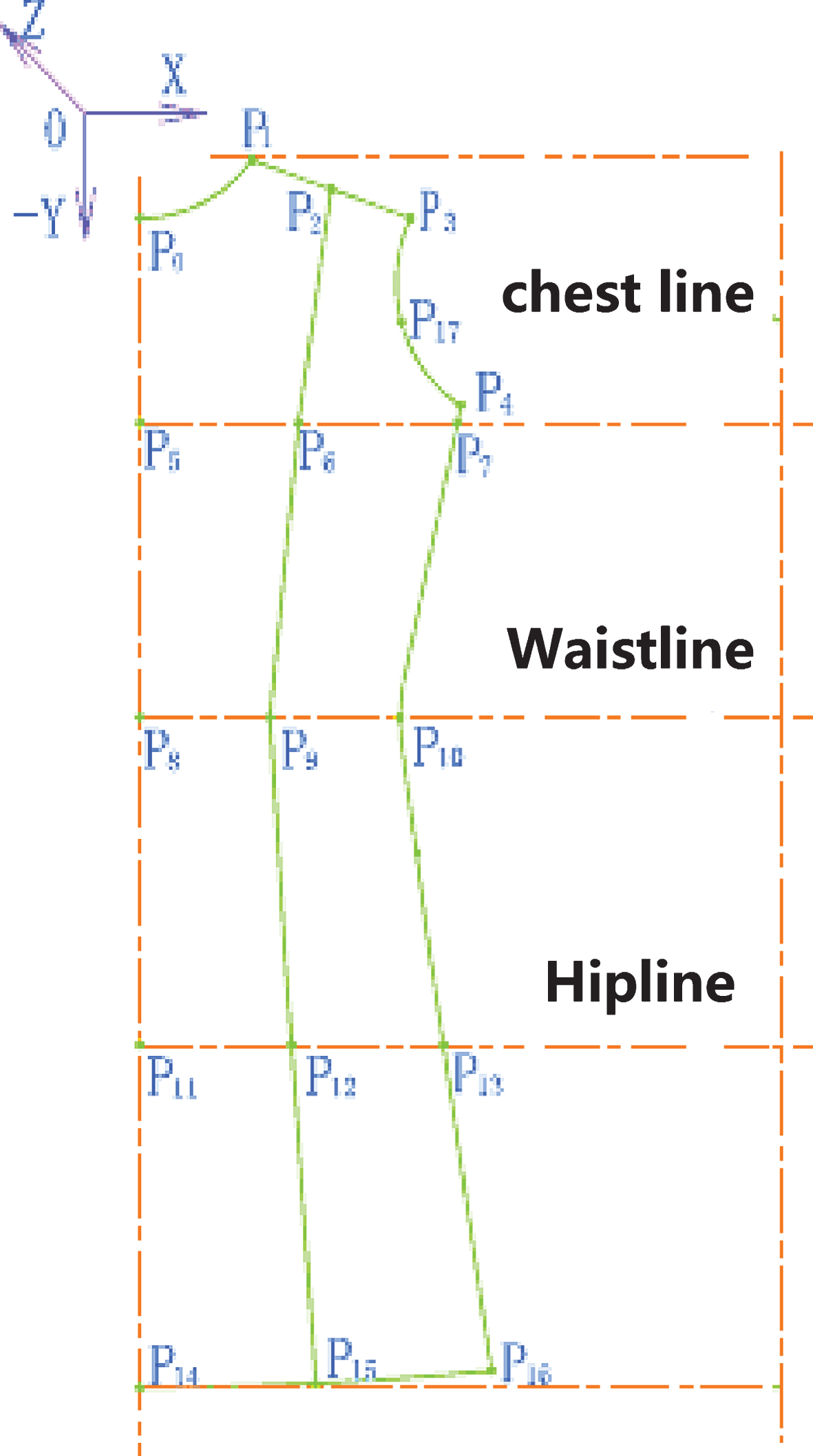
According to the calculation formula of each part of clothing in Table 2, the three-dimensional coordinates of 18 characteristic value points in clothing drawing can be further obtained. The mark of characteristic points on the garment is shown in Fig. 6.
Fig. 6
18 characteristic value points in garment drawing.
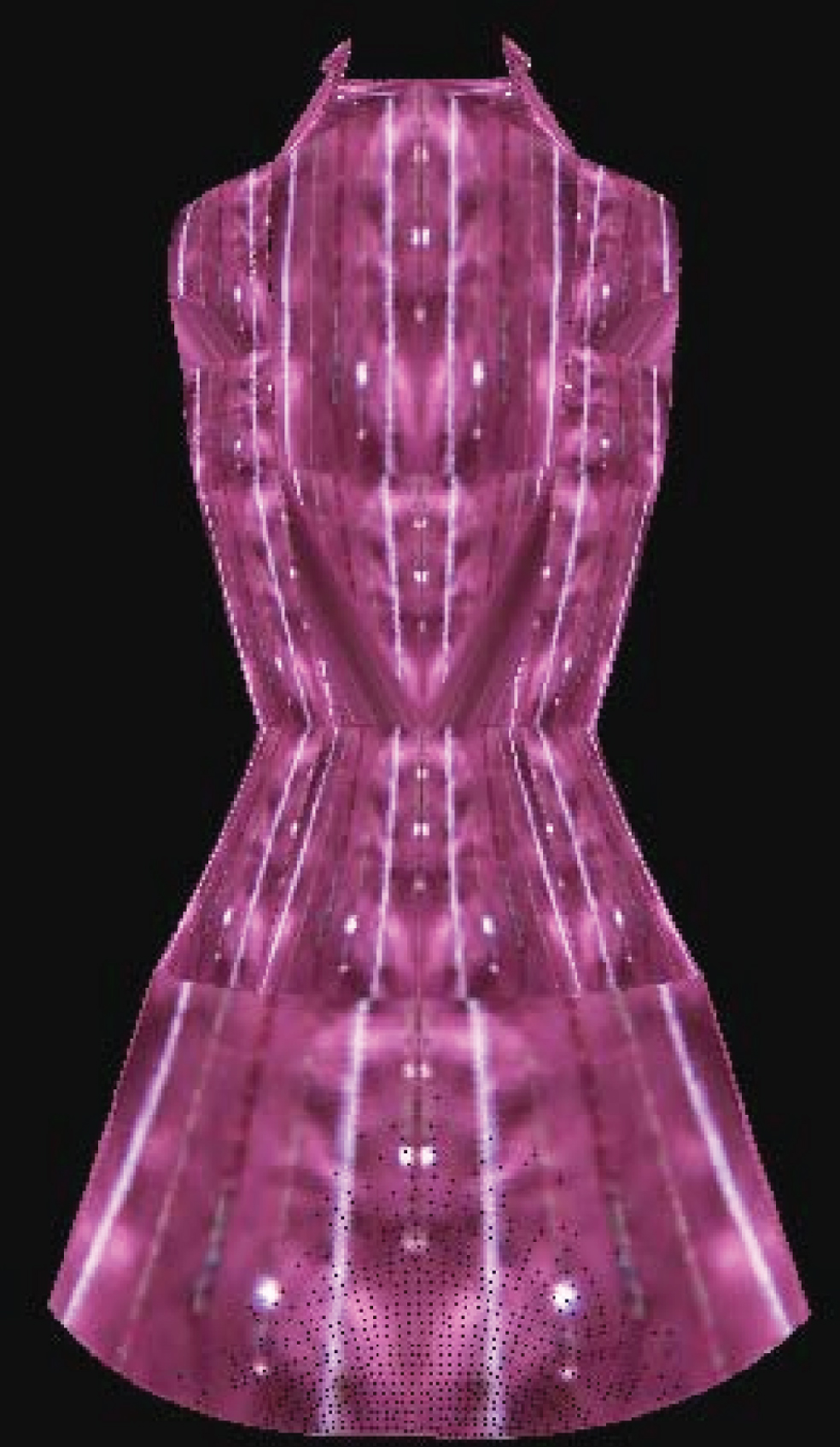
The experiment result is shown in Fig. 7.
Fig. 7
18 characteristic value points in garment drawing.
5Conclusions
This paper realizes a relatively complete fitting system based on three-dimensional model, and discusses the static simulation fitting. In this paper, the method of personalized clothing modeling based on body shape information is given, and the clothing model of the selected style is obtained for customers to appreciate, which can be further extended to the observation system with greater freedom. In the aspect of technology, the paper proposes to use the parametric method to fit the characteristic curve of clothing, and uses the control vertex to design the shape of clothing, and gives four forms of stitching parabola space and the algorithm to solve the control point. In this paper, based on the principle of scale method, a 3D coordinate transformation model of feature points is established, and a 3D rigid clothing model based on Bezier surface construction method is obtained. In this paper, the rigid body modeling method is also used for the non-rigid body object, which can not only reflect the three elements of clothing color, style and fabric, but also effectively deal with the problem of stitching between complex clothing pieces in the simulation process. Based on the construction of rigid clothing model, the simulation process of three-dimensional clothing fitting is divided into two stages: three-dimensional rigid clothing surface construction and three-dimensional flexible clothing surface construction. In this paper, the geometric model and the physical model are combined. By solving the motion equation of the fabric and dealing with the collision detection, the three-dimensional clothing fitting model is finally simulated, and the drape effect of the static clothing of human body is vividly reproduced.
Acknowledgments
The authors would like to thank Shanghai Business School. Also, many thanks for the supporting of “Project Study on the Database Construction of the Clothing Culture of the Water and Land Painting in Ming Dynasty” supported by Shanghai Young talents in Science and Technology (Project number is –20YF1434700).
References
[1] | Zhu N. , Zhang D. , Wang W. , et al., A Novel Coronavirus from Patients with Pneumonia in China, The New England Journal of Medicine 382: ((2020) ), 727–733. DOI: 10.1056/NEJMoa2001017 |
[2] | Bricken M. and Byrne C.M. , Summer Students in Virtual Reality: A Pilot Study on Educational Applications of Virtual Reality Technology, Virtual Reality 1993: , 199–217. |
[3] | Zhu L. , Application and Design of Virtual Reality Technology in Railway Maintenance Training, International Journal of Technology Management 2013: (4), 42–44. |
[4] | Livatino S. , Muscato G. and Privitera F. , Stereo Viewing and Virtual Reality Technologies in Mobile Robot Teleguide, Robotics IEEE Transactions on 25: (6) ((2009) ), 1343–1355. |
[5] | Howard T. , Marchal M. , Lécuyer A. , et al., PUMAH: Pan-Tilt Ultrasound Mid-Air Haptics for Larger Interaction Workspace in Virtual Reality, IEEE Transactions on Haptics 13: (1) ((2020) ), 38–44. |
[6] | Wang Y. , Yu H. and Shi F. , Study on the security of information system authentication scheme based on the fuzzy number intuitionistic fuzzy information, Journal of Intelligent and Fuzzy Systems 37: (3) ((2019) ), 1–9. |
[7] | Huang J.Y. , An omnidirectional stroll-based virtual reality interface and its application on overhead crane training, IEEE Transactions on Multimedia 5: (1) ((2003) ), 39–51. |
[8] | Hanssens J.M. , Allard R. and Faubert J. , Progressive lenses distortions effect on postural stability in virtual reality environment, Journal of Vision 7: (9) ((2010) ), 1026–1026. |
[9] | Jackson K.L. and Polisky L.E. , Wearable computers: Information tool for the twenty-first century, Virtual Reality 3: (3) ((1998) ), 147–156. |
[10] | Venkataraman S. , AGAVE (Access Grid Autostereo Virtual Environment), Transactions on Graphics 24: (3) ((2005) ), 894–903. |
[11] | Cornbleth T. , Evaluation of Goal Attainment in Geriatric Settings, Journal of the American Geriatrics Society 26: (9) ((1978) ), 404–407. |
[12] | Munson J. and Pasqual P. , Using Technology in Autism Research: The Promise and the Perils, Computer 45: (6) ((2012) ), 89–91. |
[13] | Semeraro F. , Frisoli A. , Bergamasco M. , et al., Virtual reality enhanced mannequin (VREM) that is well received by resuscitation experts, Resuscitation 80: (4) ((2009) ), 489–492. |
[14] | Wyshynski S. and Vincent V.J. , Full-Body Unencumbered Immersion in Virtual Worlds, Virtual Reality 1993: , 123–142. |
[15] | Soares A. , Andrade A. , Lamounier E. , et al., The Development of a Virtual Myoelectric Prosthesis Controlled by an EMG Pattern Recognition System Based on Neural Networks, Journal of Intelligent Information Systems 21: (2) ((2003) ), 127–141. |
[16] | Liu Q. , Yang F. and Li C. , AWBING plus algorithm for generic object proposal generation, Journal of Intelligent and Fuzzy Systems 36: (6) ((2019) ), 1–17. |
[17] | Yang Y.I. , Yang C.K. and Chu C.H. , A virtual try-on system in augmented reality using RGB-D cameras for footwear personalization, Journal of Manufacturing Systems 33: (4) ((2014) ), 690–698. |
[18] | Wachs J.P. , KLsch M. , Stern H. , et al., Vision-based hand-gesture applications, Communications of the ACM 54: (2) ((2011) ), 60. |
[19] | Sodhi R. , Poupyrev I. , Glisson M. , et al., AIREAL: Interactive Tactile Experiences in Free Air, ACM Transactions on Graphics 32: (4CD) ((2013) ), 134.1–134.10. |
[20] | Bau O. and Poupyrev I. , REVEL: Tactile Feedback Technology for Augmented Reality, ACM Transactions on Graphics 31: (4CD) ((2012) ), 89.1–89.11. |
[21] | Harper R. , Culham L. and Dickinson C. , Head mounted video magnification devices for low vision rehabilitation: a comparison with existing technology, British Journal of Ophthalmology 83: (4) ((1999) ), 495–500. |

