
Variable universe fuzzy control for excitation system of HTS machine
Abstract
The generator is an important component of the power system and, as a prerequisite for the normal work of the generator; one of the preconditions of excitation of a system running well will directly affect the operation of the motor characteristics and heavily influence the normal operation of the power system. In the excitation system, the control portion of the excitation system is the key to whether a system can effectively resist all kinds of emergencies. Regarding the excitation system of a high temperature superconducting machine, this paper proposes the design of an excitation system control strategy. Combining fuzzy control and conventional PID control strategy, the proposed composition has the advantages of an excitation control strategy, which can achieve a precise control purpose, and provides good adaptive ability and robustness. And on this basis, the proposed composition seeks to combine variable universe fuzzy control, to further improve the control precision of the system. The fuzzy PID control system simulation model and the variable universe fuzzy PID control are investigated. Results are compared and indicate that the variable universe fuzzy PID control demonstrates better dynamic and static performance.
1Introduction
With the support of new materials in the field provided by the 863 plan, the CSIC 712 research institute has successfully developed China’s first 1000 kW HTS Motor and achieved stable full-power operation in April, 2012. In July, 2012, the “1000 kW HTS Motors” project of the 863 plan passed technical inspection. This indicates that China already has the ability to design megawatt-class HTS motors with manufacturing capabilities, and has become one of the few countries to have mastered key technologies of the HTS motor. However, the current study of motor is far from good, and the development of a supporting system for the HTS motor remains a slow process, especially for high temperature superconducting motor excitation systems. For excitation systems, the control strategy determines the system performance instability and fault conditions, which improves the performance of the excitation control system. Thus, the control strategy has great influence on the safe and stable operation of synchronous generators and power systems. Excitation control plays an important role in determining whether the system will work in the normal state or fault conditions; thus, the excitation system control strategy is indispensable. The performance of the excitation system plays a key role in HTS motor operation, and has significant impact on several key technical indices such as reliability, stability and power quality indicators. The conventional PID control strategy is simple in structure, with certain robustness, easy implementation, and steady-state astatic control. The precision can meet general requirements at the industrial level. With the development of a power system, it has become highly nonlinear and time-varying, and conventional PID control of excitation has been unable to meet the requirements of modern power systems, necessitating the search for other effective control methods.
Chen Zhifei presented the adaptive neuro-complex fuzzy inferential system (ANCFIS) [3], providing a good method for the implementation of complex fuzzy rules; the authors have presented the architecture and learning algorithm for ANCFIS. Amitava Chatterjee proposed a control strategy of stable state-feedback fuzzy controller used for flexible robotic arms [1], in which the controller was designed on the basis of a neuro-fuzzy state space model; this strategy has solved the stability condition problems and has been successfully implemented on a real robotic arm. Zhang Wen Ling proposed a fuzzy control system using an iterative feedback tuning algorithm characterized by setting the step size in order to guarantee the stability of the fuzzy control system [14].
2Structure of HTS machine excitation system
The structure of an HTS motor excitation system is shown in Fig. 1. The composition of the excitation system is composed of a power system stabilizer, rotating rectifier and the control section; the control strategy is described in the following sections. In addition to an excitation system, the input is an external preset, and the output will be exported to the HTS motor rotor winding.
3Modeling of excitation system of HTS machine
3.1Modeling of rotate rectifier
The working principle of a diode rectifier is based on single guide electrical characteristics. To ensure the AC input DC output needs to ensure that only one diode is conducting within the negative and the positive of the two groups at the same time. The remaining diode has a non-positive voltage and therefore does not turn on. In the circuit load, rectification is realized by through continuous transformation of the conduction sequence: conversion occurs six times, with six conversion points. The DC voltage output rectifier is for envelope line voltage. Six uniform wave heads appear in one cycle, the average load current of each interval is the same, and the load voltage is equal to the corresponding average value, which is also the conversion point.
(1)
(2)
When the load is the large inductance and resistance, inductance cannot fluctuate in a very stable output current, and current circuit load is a constant:
(3)
3.2Modeling of PSS
In a power system, low frequency oscillation is always a difficult problem to solve. In order to overcome this problem, scientists have developed a device called a power system stabilizer. As an additional excitation control technique, it is used to suppress low frequency oscillation. The device suppresses the low frequency oscillations by importing an additional signal ahead of speed into the excitation system. Through this signal, a corresponding positive damping torque can be produced; the torque can be used to produce the harmonic excitation regulator to mediate the negative feedback of the negative damping torque. In the working process of the PSS, in addition to the speed signal, it also requires other signals associated with vibration signal sampling, such as active power and frequency; the signal is processed and blended into the original signal, which can more effectively negate the damping signal.
The input signal is possible for the above mentioned comprehensive sampling signal, but the complexity is higher, which makes it less conducive to industrial manufacturing. Therefore, different countries choose different input signals. In some countries, such as Japan, ΔP is used as input, but more countries use Δω, the rotating speed, as input. In this paper, in order to raise the accuracy of the result, ΔP and Δω are both used as input. The mathematical model of a power system controller is shown in Fig. 2.
The mathematical model of an HTS machine is rather complicated, so the details will not be introduced here. The simulation will adopt the corresponding mathematical model.
4The fuzzy PID control strategy design and simulation of excitation system
4.1The PID control strategy design and of excitation system
The working principle of PID control strategy is very simple. The working principle of the strategy is based on the system error as input, using the error ratio and differential integral, calculating three aspects of different combinations as an output control. Figure 3 depicts a schematic diagram of a conventional PID control system [12].
In an automatic control system, the control strategy and the controlled object are two very important components. The expression of the terminal voltage deviation signal is given below; the result of the difference between the given r (t) and the actual output y (t) is shown in Fig. 3.
The PID algorithm has several inherent defects. First of all, the primary control object of the PID algorithm is for a linear system, requirements for the accuracy of system modeling are high, and the control effect for a complex system is poor. Secondly, the saturation amplifier will lead the PID control strategy to weaken the differential signal; meanwhile, due to the changing object parameters, the control effect will be greatly reduced. Finally, the adaptive ability of the traditional PID algorithm to system load changes or jamming from interference is weak. Therefore, the traditional PID control strategy is only suitable for low load, nonlinear, low disturbance conditions [9].
4.2The fuzzy PID control strategy design for excitation system
A fuzzy PID excitation control strategy for an HTS motor uses changes in the deviation between the terminal voltage of the generator and a given value as a feedback signal, ruling out the corresponding control signals through fuzzy logic inference, and then inputting the signal into the excitation system of the HTS machine to realize the control of the machine.
As a kind of adaptive PID control algorithm, the characteristics of fuzzy PID include adding a fuzzy reasoning algorithm to conventional PID. Fuzzy control does not depend on a precise mathematical model and has low requirements regarding the linear degree of the control object, effectively achieving anti-interference, and demonstrating good adaptability and robustness. The fuzzy PID control algorithm combines the excellent performance of the conventional PID control algorithm with the fuzzy control algorithm, creating a more intelligent PID control algorithm.
The process principle of a fuzzy inference system is shown in Fig. 4.
For the excitation control system designed in this paper, the input quantity is the deviation of the terminal voltage and the expected value e, and the changing rate of deviation e’ These values have physical meanings and their own changing scopes; the range is known as the basic theory of domain of the system. The controlled output variable u represents the change range of parameters requested by the controlled object, the control volume for precise values, known as the basic theory of domain output variable fuzzy control strategy. The first step is to blur the two actual input variables and the output variable [2].
The input values e and ec stand for the voltage deviation and changing rate of voltage deviation under the fuzzy control strategy; outputs Δk p , Δk i , Δk d stand for the processed three parameters of the PID strategy. Δk p represents the increment of the PID proportion factor, Δk i is the increment of PID integral factor, Δk d is the increment of PID differential factor, and u represents the output of the fuzzy PID control strategy.
The design of the PID algorithm needs to design the fuzzy control model. The fuzzy control strategy is a two-input single-output model, according to the fuzzy control strategy, with design outlined as follows.
Fuzzy quantitative:
Set the fuzzy subset of the input e, ec and the output Δk p , Δk i , Δk d as follows:
These variables represent “Negative Big”, “Negative Middle”, “Negative Small”, “Zero”, “Positive Small”, “Positive Middle” and “Positive Big” respectively.
Set domain of e to [–0.3, 0.3], and select Gaussian as the membership function; set the domain of ec to [–0.1, 0.1], select Gauss type as membership function; set domain of Δk p to [–1, 1], select triangle type as membership function; set domain of Δk i to [–0.1, 0.1], select triangle type as membership function; set domain of Δk d to [–0.05, 0.05], select triangle type as membership function. The core of the fuzzy system is a knowledge base, and the core of the knowledge base is the fuzzy rule, which is used to express the fuzzy logic relationship between input and output. The fuzzy rule of this paper is based on summarized and developed knowledge of control experts and practical experience; the design principle is to ensure that the system demonstrates the best dynamic performance. The fuzzy rules are shown in Table 1.
Fuzzy PID control quantity u is obtained by using the PID control algorithm, expressed by Equation (4):
(4)
4.3Excitation system simulation in the fuzzy PID control strategy
In the fuzzy control strategy designed above, the three values Δk p , Δk i , Δk d are not fixed values, so unlike the ordinary PID simulation construction in which three values are set as fixed values, the three values are used as the input value for processing. Meanwhile, fuzzy control strategy not only requires terminal voltage deviation e as an input, but also requires ec (the changing rate of e) as another input. The fuzzy PID control strategy simulation model is shown in Fig. 5 [6].
Set simulation time as 10 s, algorithm as ode23. Set each control parameter of PID control strategy as: If K p = 20, K i = 4.2, K d = 0.21, then set quantification factor K e and K ec of the fuzzy control strategy as follows K e = 3, K ec = 1. Set the scaling factor to K up = 26, K ui = 1, K up = 10. Simulation result under normal working conditions is shown in Fig. 6.
The simulation model above represents an HTS machine under normal conditions; however, there may be many unpredictable emergencies, thus these conditions must also be solved. Under normal working conditions, the machine sometimes must face output short circuit, tested in this article by simulating the terminal voltage short circuit to analyze the moderating effect of the excitation system in the face of the fault. Failure time is set from 15 s to 15.1 s, the simulation time is set to 20 s, and all other parameters remain the same as under conventional working conditions. The simulation responses of fault voltage and excitation voltage are shown in Figs. 7 and 8 respectively.
5Variable universe fuzzy PID control strategy design and simulation for excitation system
5.1Variable universe fuzzy PID control strategy design for excitation system
In the algorithm introduced by fuzzy control strategy, there will be some inevitable nonlinear components; this is due to the complex fuzzy rules, which will weaken the control effect. The accuracy of control depends on the number of control rules, membership function selection and expert experience. Although fuzzy control has strong robustness, its adaptive ability is poor; the variable universe fuzzy control is effective in mitigating this problem.
The design of the variable universe fuzzy control strategy does not require much expert knowledge in this field, only the general trend of the rules. Compared to the conventional fuzzy control strategy, there are fewer requirements of control rule membership functions and equidistant partition, and a simplified design with higher accuracy. Thus, the variable universe fuzzy control is a kind of high precision fuzzy adaptive algorithm, which can deal with nonlinear control objects and the difficulties in modeling and changing model parameters. A common variable universe fuzzy control principle diagram is shown in Fig. 9.
Set the double-input single-output fuzzy control system as an example. Set the domain of input e to X 1 = [- E, E]; domain of input ec to X 2 = [- EC, EC]; and domain of output u Y = [- U, U]. Set the fuzzy partition on X i to A = {A ij } and set fuzzy partition on Y to B = {B j }, according to the common fuzzy control rules explained in Equation (5).
(5)
Set the peak point of A i j to x i j; set the peak point of B j to y j ; set the interpolation function to F (e, ec). The rule above can be transformed into Equation (6):
(6)
(7)
– Duality: γ (x) = γ (- x);
– Zero protecting: γ (0) =0;
– Monotonicity: γ (x) strictly monotone increasing on [0, U];
– Coordination: ∀x ∈ [0, 1] , |x| ≤ λ (x) U;
– Regularity: γ(±U) = 1.
There are two typical methods for selection of scaling factors: based on the mathematical model of slip factor, and based on fuzzy reasoning. Whichever method is used, its ultimate goal is to ensure that every change of domain is the best to achieve the best control performance. In this paper, the first method is deemed to be more appropriate [15].
According to the definition and properties of the extension factor, the scaling factor is expressed as a function of the output variables common domain extension factor of input e and output u is described in Equation (8):
(8)
Fuzzy control of the system is achieved by computer processor, in order to translate to other control strategies. This paper selects a discrete time system for control strategy design [8]. Set the initial control rule to R (0) = R, X 1 = [- E, E], X 2 = [- EC, EC], and set linear output primitives of Y = [- U, U] as {A ij } (1≤i≤p, 1≤j≤q), {B j } (1≤j≤q), {C ij } (1≤i≤p, 1≤j≤q). Peak points should meet the following requirements:
Let x 1i (0) = x 1i , x 2j (0) = x 2j , y ij (0) = y ij and x 1i (k), x 2j (k) (k is a constant) represent the variable domain of x 1 i, x 2 j. -U = y 11 < y 12 < … < y pq = U. y i j is the system output while the inputs are x 1 i, x 2 j. Set the membership function as a i (x 1 (k) , k) , b i (x 2 (k) , k) to achieve double-input single-output control strategy by the following steps:
Step 1: input x 1 (0)∈ X 1, x 2 (0)∈ X 2 gain output Equation (9):
(9)
Step 2: gain output from system by laying y (1) on object; use system feedback to compare to reference input; gain input of control strategy x 1 (1), x 2 (1). y s t (0) represents initial time domain value. We obtain:
(10)
(11)
(12)
(13)
Step k: obtain system output by laying y (k) on object feedback to system to compare with reference input; gain input of control strategy x 1 (k), x 2 (k). We obtain:
(14)
(15)
(16)
(17)
Obtain the double-input single-output self-adaptive fuzzy control strategy for output from above:
(18)
Additionally, x 1 (k) →0, x 2 (k) →0, y (k + 1) →0.
5.2Excitation system simulation under variable universe fuzzy PID control strategy
Variable universe fuzzy control strategy is designed according to the design principle detailed in Section 3, and this paper uses the M language to write the variable universe fuzzy control strategy, using S-function to realize it. Set the expansion factor of input domain to: α (x) =1 - λe -kx (λ ∈ (0, 1) , k > 0); set λ = 0.7, k = 0.5, x is equal to e or ec. Set the expansion factor of output k p and k i to: β 1 = 2|e|, β 2 = 1/(|e|+0.6).
The simulation results under normal working conditions are shown in Fig. 12.
The simulation responses of fault voltage and excitation voltage are shown in Figs. 13 and 14, respectively.
Details of the simulation are as follows:
Rating power: 1000 MW; Rating voltage: 24 kV; Rating rew: 3000r/min; Stator resistance: R a = 0.0038Ω.
The controller parameters are as follows: K p = 20, K i = 4.2, K d = 0.21. The scaling parameters are: K e = 3, K ec = 1, K up = 26, K ui = 1 and K ud = 10.
6Analysis of HTS machine excitation system simulation
The simulation responses of normal working conditions under two kinds of control strategy indicate that response under fuzzy PID control strategy does not overshoot, and goes into a steady state after a brief wobble without static error. Under variable universe fuzzy control strategy, excitation voltage response is relatively smoother than under common fuzzy control, not only without overshoot, but also demonstrating some variation before entering into a steady state. Section 5 provided the universe fuzzy PID control strategy design and simulation for excitation system, which was the foundation of this section.
Performance comparison of the two kinds of control strategies under conventional working condition is shown in Table 2.
Conclusions are as follows:
Although fuzzy PID is faster than variable universe fuzzy PID on rise time, but the actual response curve indicates that before entering into steady-state error, variation of the fuzzy PID is larger and the actual regulation time is longer than that achieved by variable universe fuzzy PID.
During the normal working state, the control effect of variable universe fuzzy control is better than that of fuzzy PID.
Under fault conditions, through the comparison of two contrast response curves of terminal voltage, regulation time of voltage response under fuzzy PID is found to be significantly longer than the terminal voltage under the control of the variable universe fuzzy PID control strategy; specific performance comparison is shown in Table 3. Table 3 indicates that under fuzzy PID control, the time adjustment of terminal voltage is 0.03 s, which is longer than that under control of variable universe fuzzy PID. Comparison of the two groups of waves proves that variable universe fuzzy PID is relatively better than fuzzy PID in control precision and effect.
The specific performance comparison of excitation voltage is shown in Table 4.
Table 4 indicates that in adjusting time and steady-state error, the control performance of variable universe fuzzy PID control has an absolute advantage.
7Conclusions
This paper uses the fuzzy control theory, according to the control requirements of excitation systems and characteristics, to construct a variable universe fuzzy PID control strategy by combining the traditional PID with variable domain optimization. The simulation results indicate that variable universe fuzzy PID control has better control accuracy, response speed and anti-interference ability in the transfer of power, voltage regulation and under large disturbances, which can effectively improve the system state variable and output dynamic as well as the static performance and the stable operation of the system.
Acknowledgments
This work was supported in part by Research Fund for the Doctoral Program of Higher Education 20132304120015, Doctoral Scientific Research Foundation of Heilongjiang under No. LBH-Q14040, National Defense Fundamental Research Funds under No.IEP14001, and Fundamental Research Funds for the Central Universities under HEUCFX41305.
References
1 | Chatterjee A, Chatterjee R, Matsuno F, Endo T (2008) Augmented stable fuzzy control for flexible robotic arm using LMI approach and neuro-fuzzy state space modeling IEEE Transactions on Industrial Electronics 55: 3 1256 1270 |
2 | Abd AN (2006) Alla, Simulation Model of Brushless Excitation System: HoushiPower Plant (China) Proceedings of 2006 International Symposium on Distributed Computing and Applications to Business 4 Engineering and Science |
3 | Zhifei C, Aghakhani S, Man J, Scott D (2011) ANCFIS: A neurofuzzy architecture employing complex fuzzy sets IEEE Transactions on Fuzzy Systems 19: 2 305 322 |
4 | Ishizuka D, Kim SB, Hayashi N, Kitamura H, Miyazawa D (2014) Numerical study on split coil-shaped HTS bulks to improve the field homogeneity for compact NMR relaxometry magnets Physics Procedia 58: 290 293 |
5 | Feriyonika , Dewantoro G (2013) Fuzzy sliding mode control for enhancing injection velocity performance in injection molding machine International Journal of Artificial Intelligence 10: S13 75 87 |
6 | Bo GH, Yuan WF, Hui C (2007) Simulation of a marine controllable phase-compounding excitation system International Journal of Plant Engineering and Management 4: 227 233 |
7 | Xun JJ (2008) High Temperature superconductivity in the past twenty years part 2–towards to practical applications Journal of Electronic Science and Technology of China 2: 237 254 |
8 | Jie L, Kai Z, Pan LP, Nian HX, Di QZ (2014) Coded Excitation System for Stationary Target Detection Using Multi Segment Coding Proceedings of 2014 International Conference on Industrial Engineering and Information Technology IEEE Beijing Section |
9 | Kovalev LK, Ilushin KV, Penkin VT, Kovalev KL, Koneev SM-A, Modestov KA, Larionoff SA, Gawalek W, Oswald B (2001) HTS electrical machines with YBCO bulk and Ag–BSCCO plate-shape HTS elements: Recent results and future development Physica C: Superconductivity and its Applications 354: 34 39 |
10 | Jian P, Hui L, Xi ZC (2002) DTLC Series Large-scale Synchronous Motors Excitation System Controller for Electric Power Irrigation and Drainage System and Application Proceedings of the International Symposium on Electrical Engineering Education, China Electro-technical Society (CES) 5 |
11 | Precup R-E, Marius L, Tomescu B, Radac M-B, Petriu EM, Preitl S (2012) Claudia-Adina Dragos, Iterative performance improvement of fuzzy control systems for three tank systems Expert Systems with Applications 39: 8288 8299 |
12 | Guang WZ, Xun JJ, Guang GY, Guo ZJ (2008) SVPWM techniques and applications in HTS PMSM machines control Journal of Electronic Science and Technology of China 2: 191 197 |
13 | Bo W, Jun LJ (2011) A method for online analyzing excitation systems performance based on PMU measurements Proceedings of 2011 International Conference on Advanced Power System Automation and Protection(APAP 2011) 1538 1542 |
14 | Ling ZW, Jie YY, Qin WJ (2007) Excitation System Test Device Based on Virtual Instrument Proceedings of 2007 8th International Conference on Electronic Measurement & Instruments(ICEMI’ 2007) III: |
15 | Fei ZT, Jing Y, Min MF (2013) Resource Allocation Network based Neural PID Adaptive Control for Generator Excitation System Proceedings of 25th Control & Decision Conference 1352 1357 |
Figures and Tables
Fig.1
Model structure of HTS machine.
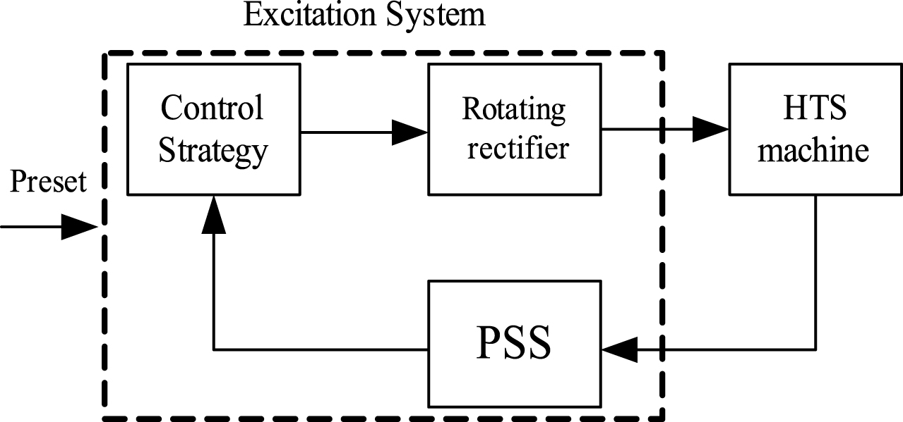
Fig.2
Model of PSS.
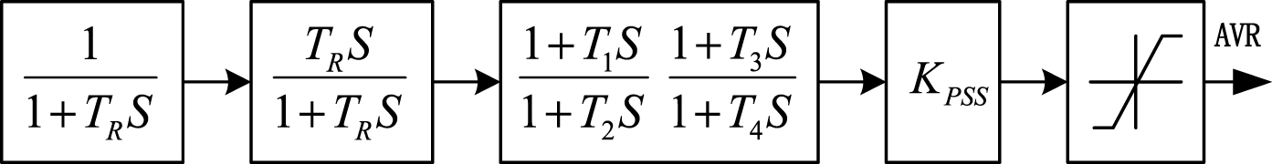
Fig.3
Conventional PID control system block diagram.
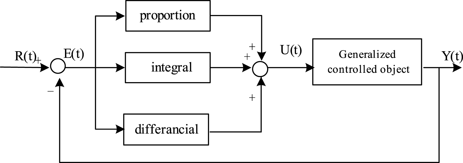
Fig.4
Structure of fuzzy system.
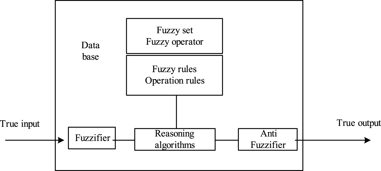
Fig.5
Fuzzy PID control strategy simulation model.
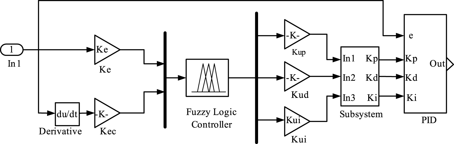
Fig.6
Excitation voltage response under fuzzy PID control strategy.
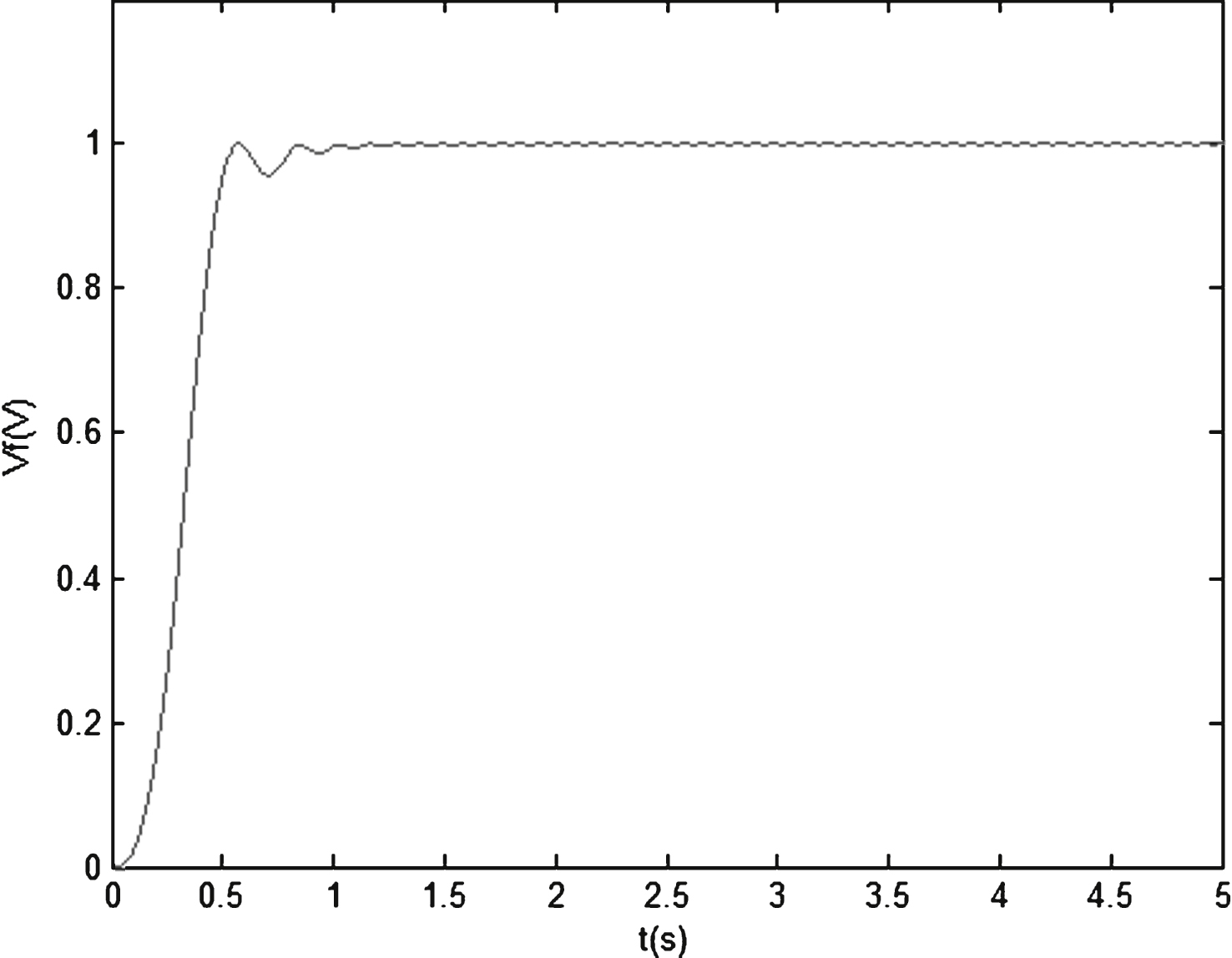
Fig.7
Voltage response simulation of short circuit fault under fuzzy PID control.
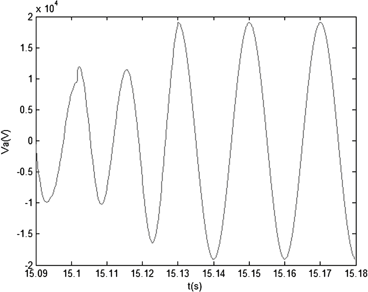
Fig.8
Excitation voltage response simulation of short circuit fault under fuzzy PID control.
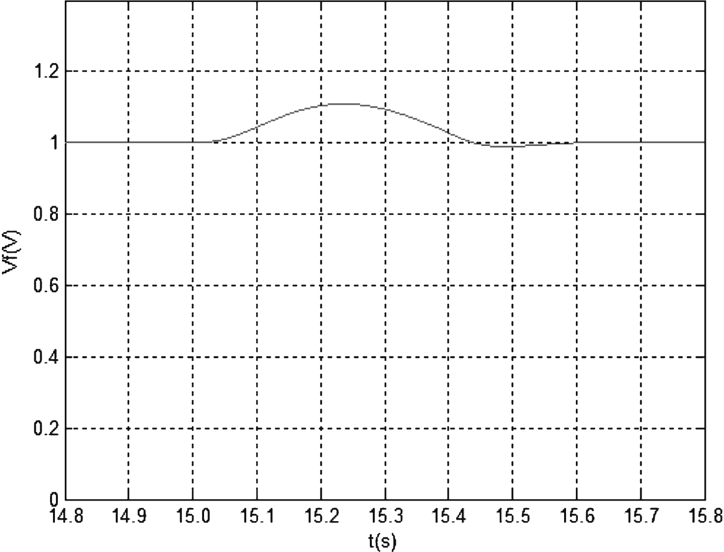
Fig.9
Variable universe fuzzy control principle diagram.
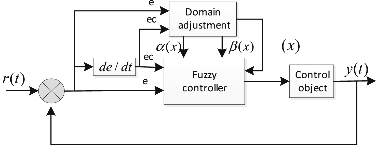
Fig.10
Initial domain of output variable.
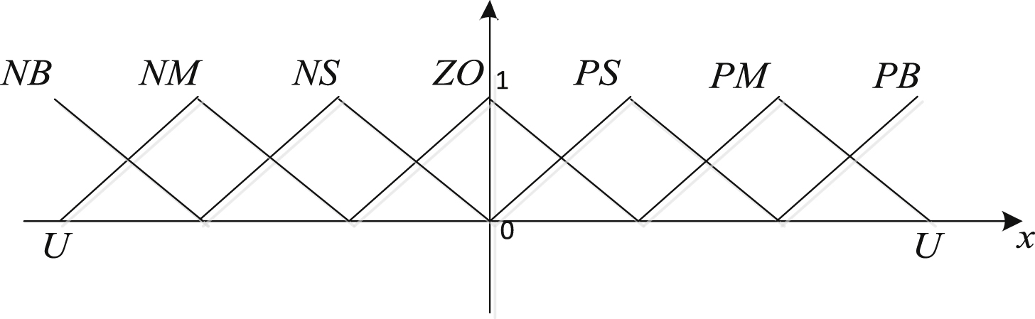
Fig.11
Output variable universe scale.
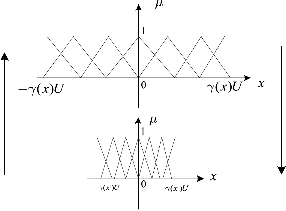
Fig.12
Excitation voltage response under variable universe fuzzy PID control.
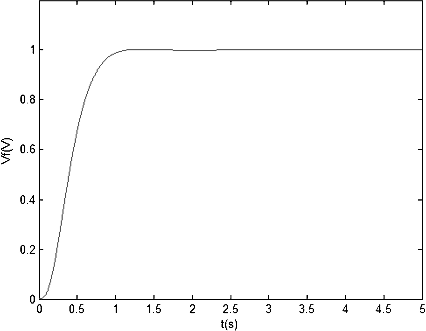
Fig.13
Voltage of the short circuit fault simulation response under the variable universe fuzzy PID control.
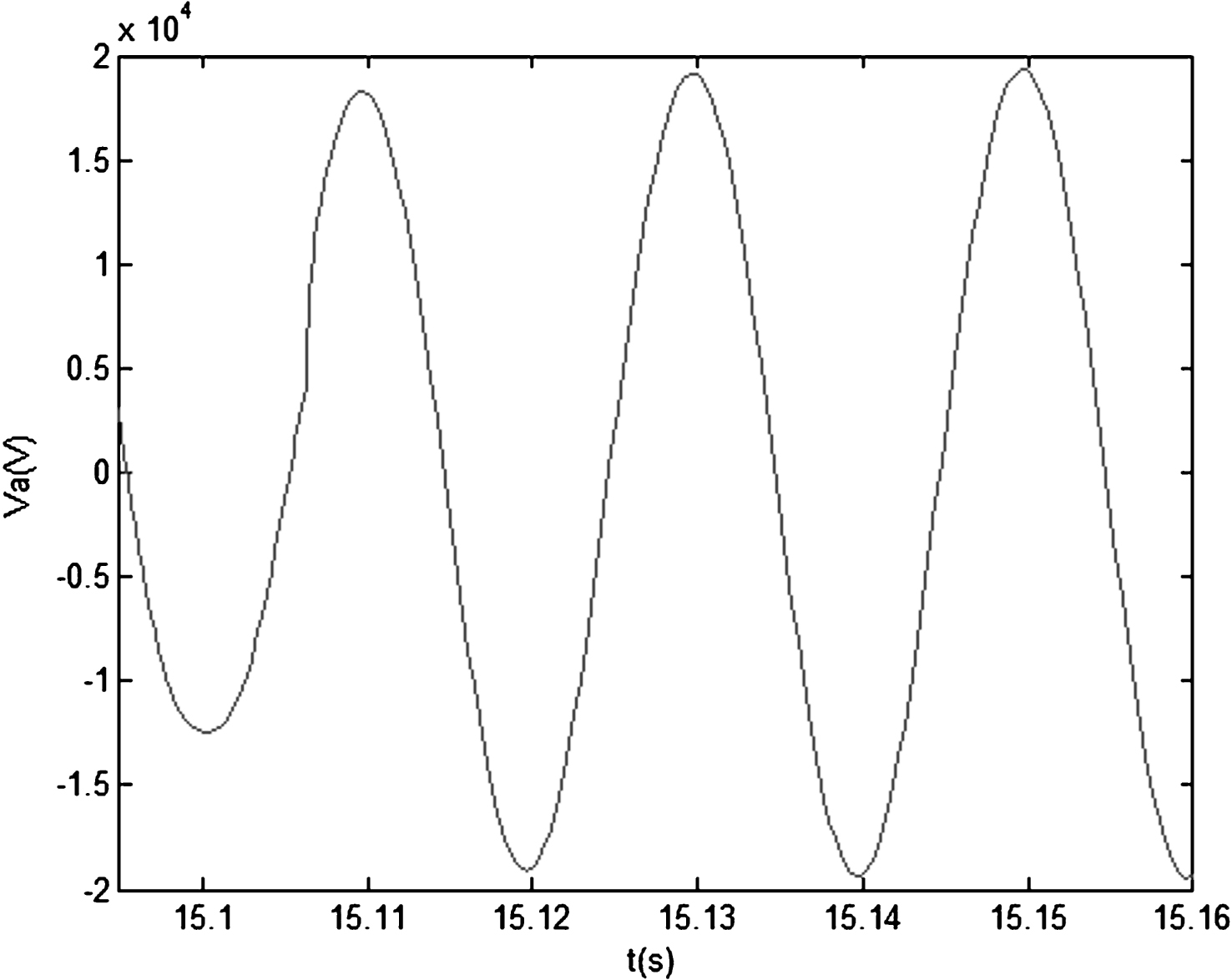
Fig.14
Excitation voltage short circuit fault simulation response under variable universe fuzzy PID control.
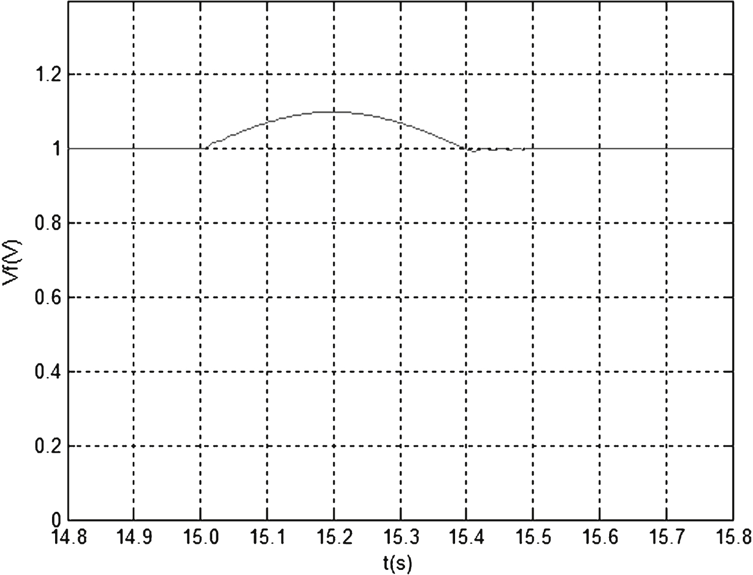
Table 1
Fuzzy PID control rules
| ec/e | NB | NM | NS | ZO | PS | PM | PB |
| NB | PB/PB/PB | PB/PB/PB | PB/PS/PM | PM/PS/PM | PM/PS/PM | PM/PS/PM | PS/PS/PS |
| NM | PB/PS/PB | PB/PS/PB | PM/PS/PM | PM/PS/PM | PS/PS/PS | PS/PS/PS | ZO/ZO/ZO |
| NS | PM/PB/PS | PM/PB/PS | PM/PM/PS | PS/PS/PS | ZO/NM/ZO | ZO/NM/ZO | ZO/NM/ZO |
| ZO | PM/PM/Z0 | PM/PM/Z0 | PS/PM/ZO | ZO/ZO/ZO | NS/NM/ZO | NM/NM/ZO | NM/NM/ZO |
| PS | ZO/PM/ZO | ZO/PM/ZO | ZO/PM/ZO | NS/NS/NS | NS/NM/NS | NM/NB/NS | NM/NB/NS |
| PM | ZO/ZO/ZO | NS/NS/NS | NS/NS/NS | NM/NS/NM | NM/NS/NM | NB/NS/NB | NB/NS/NB |
| PB | NS/NS/NS | NM/NS/NM | NM/NS/NM | NM/NS/NM | NB/NS/NM | NB/NB/NB | NB/NB/NB |
Table 2
Performance comparison of two control strategies under normal working conditions
| Performance index | ||||
| Type of control | Rise time(s) | Overshoot(%) | Setting time(s) | State error(%) |
| Fuzzy PID | 0.35 | 0.2 | 0.85 | 0.2 |
| Variable universe fuzzy PID | 0.5 | 0.1 | 0.8 | 0 |
Table 3
Comparison of voltage performance under two control strategies in short circuit state
| Performance index | |||
| Type of control | State error(%) | Number of oscillation | Oscillating time(s) |
| Fuzzy PID | 1.8 | 2 | 0.03 |
| Variable universe fuzzy PID | 0.4 | 0 | 0.01 |
Table 4
Comparison of excitation voltage under two kinds of control strategies in short circuit condition
| Performance index | ||
| Type of control | Setting time(s) | State error (%) |
| Fuzzy PID | 0.43 | 0.2 |
| Variable universe fuzzy PID | 0.4 | 0 |

