
Biomimetic inspired, natural ventilated façade – A conceptual study
Abstract
In this paper, the authors elaborate an adaptable curtain-wall façade design concept that combines façade greening with biomimetic approaches. It begins with an overview of façade greening. Next, the paper takes a more in-depth look at prairie dog burrows and the modular growth of barnacle colonies as sources of biomimetic inspiration, including how they may be applied in technology and brought together with façade greening. The concept is expected to act contrary to the urban heat island effect by naturally cooling external building walls and thus reducing the energy needs and greenhouse gas emissions associated with artificial cooling of buildings. This is considered important, as our cities are heating up more and more, resulting in increased energy demand. The promising information gained from lab experiments on scaled façade models, based on continuous wind-generated air circulation between the building’s external wall and the façade, further initial calculations regarding natural convection, and the additional cooling effect of façade greening, can be considered a sound basis for future developments and discussions.
1Introduction
An urban heat island is an urban area that is significantly warmer than its surrounding rural areas due to human activities. This climate phenomenon was first investigated and described by Luke Howard in the beginning of the 19th century (Howard, 1818).
Tarmac, concrete and stone shape our cityscape (Minke, 2010). This supports the potential for the urban heat island effect, which has been documented over a number of decades, e.g. by the World Meteorological Organization. One result of the urban heat island effect is increased average temperatures in our cities (Santamouris, 2011). Occasionally this is due to thermal energy stored in buildings. The urban heat island effect is present in all cities and “is the most obvious climatic manifestation of urbanization” (Landsberg, 1981). Thus, the energy required for cooling buildings with artificial methods – highly dependent on non-renewable energy sources – is greater in cities, especially during the summer months. Studies also show that in the future we can expect a marked increase in greenhouse gas emissions from the use of artificial cooling methods (Riviere et al., 2008). Over the next 20 years, the figure is set to double for residential buildings, while for non-residential buildings an increase of 25% is expected.
“Cities are part of the climate change problem, but they are also a key part of the solution” (Kamal-Chaoui & Robert, 2009). They have the ability to act on climate change owing to their responsibilities towards urban structures such as buildings and façades.
Façades in particular have become an important factor in the regulation and control of the energy demand. The role of the façade is changing from being “a passive protective covering to an active regulator of a building’s energy balance” (Gosztonyi et al., 2013).
Bearing that in mind, the authors ask whether a new elaborate façade design concept combining façade greening with biomimetic approaches might allow the heat island effect in our cities to decrease by naturally cooling external building walls, and also reducing the energy needs and greenhouse gas emissions associated with cooling buildings artificially.
Combining façade greening with biomimetic approaches represents a sustainable and promising solution to address the issues mentioned above and should therefore be examined in further detail.
This paper is divided into three main sections. First, an outline of the topics of façade greening and biomimetic approaches will be given. It will explore the ways in which the two topics might be brought together for use in the construction and architecture sectors. The second part of the paper explains how to convert these approaches into the development of an adaptable curtain-wall façade design concept, related to the segmentation of the building surfaces. Finally, the results of laboratory experiments using scaled models of the façade design and initial calculations are shown, and opportunities for future development will be discussed.
2Connecting nature and architecture
2.1Façade greening
The use of plants in architecture is well established. In his time, the Roman statesman Pliny the younger (c. AD 61 – c. AD 115) already described “decorated houses”. There has since been continuous evidence of the use of plants in building design. In the Middle Ages, vines and roses extended across walls, while in the Renaissance and Baroque periods, prestigious buildings were decorated with greenery. Climbing plants were used to accentuate the architecture of classical villas and country houses. The numerous examples of turf houses such as those found in North America and Scandinavia are particularly important in the development of greening in contemporary architecture (Minke, 2010). At the beginning of the 20th century, Frank Lloyd Wright, Le Corbusier and Walter Gropius in particular, implemented the concept of green buildings in their work. Current projects featuring the use of greening in design planning include those by Patrick Blanc, Vincent Callebaut and Ken Yeang.
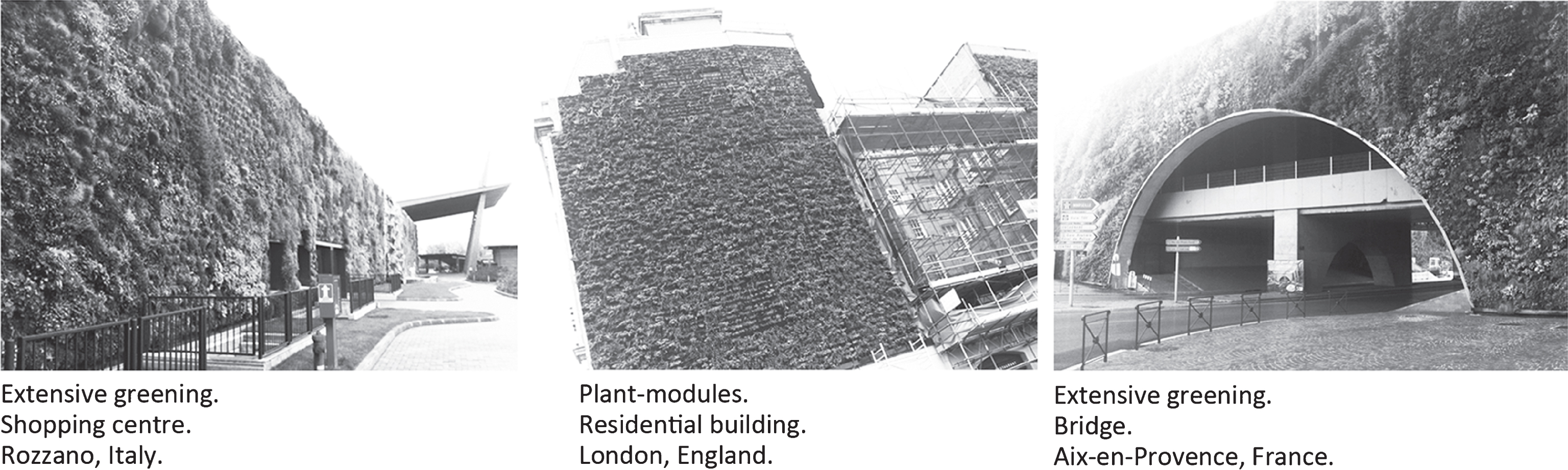
Façade greening can be subdivided into two main groups: ground-based systems and those connected to façades (Köhler, 2012). The second group is crucial for further observations in this study. This system generally forms the external wall of a building and supersedes other materials such as glass, metal plates or plaster. It does not require a direct connection with the ground and has already been field-tested using various design approaches (Fig. 1).
Fig.1
Examples of existing façade greening systems.
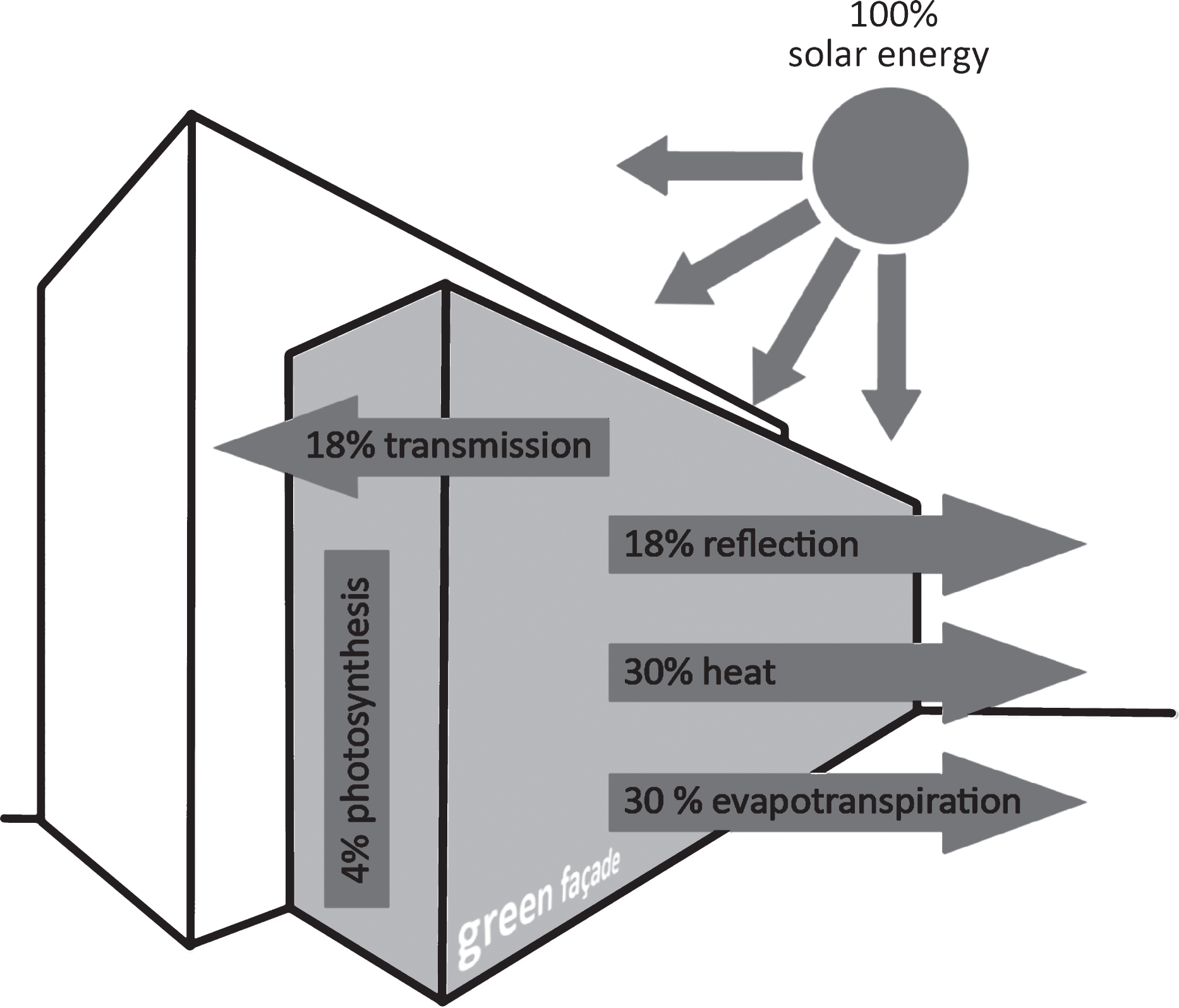
There are many reasons for employing green façades on building surfaces. One key factor is that green façades generally retain less heat and therefore present a natural way to cool external building walls (Wong et al., 2010). “Their utilization is essential and can considerably improve the microclimate of the built environment” (Eumorfopoulou & Kontoleon, 2009). This is based on so-called phytophysiological processes. Important process factors hereby that enhance this cooling effect are evaporation, reflexion, respiration and transpiration of plants and damp plant substrates, which further support the cooling effect (Bass, Martens & Alcazar, 2008; Krusche, Althaus, & Gabriel, 1982). Of 100% of the incident solar energy on a green façade, approx. 4% is bonded through photosynthesis, 18% reflected, 30% converted to heat, 30% used for evapotranspiration and only about 18% is transmitted through the foliage (Fig. 2) (Minke & Witter, 1982). Regarding the context between the reflexion of solar rays and the type of building surface, the albedo effect is also worth mentioning here.
Fig.2
Schematic diagram of energy processes on green façades. Illustration: Michael J. Paar according to Per Krusche.
2.2Biomimetic approaches
“Technology learns from nature” (translated by the authors) (Nachtigall & Pohl, 2013). Nature can act as a source of inspiration for technological thinking. A domain also known as biomimicry or biomimetics. Biomimetics is defined as the “abstraction of good design from nature” (Vincent et al., 2006) or “mimicking the functional basis of biological forms, processes and systems to produce sustainable solutions” (Pawlyn, 2011; Rawlings, Bramble & Staniland, 2012). Systems found in nature offer a huge portfolio of strategies and mechanisms that can be implemented in biomimetic designs. Therefore, biomimetics has also become increasingly important in the construction and architecture sectors, particularly in recent years.
Thus, the following section identifies biomimetic sources of inspiration that may be combined with the promising properties of façade greening to allow for the natural cooling of a building’s external walls, thereby reducing the heat island effect in our cities.
2.3Basic design
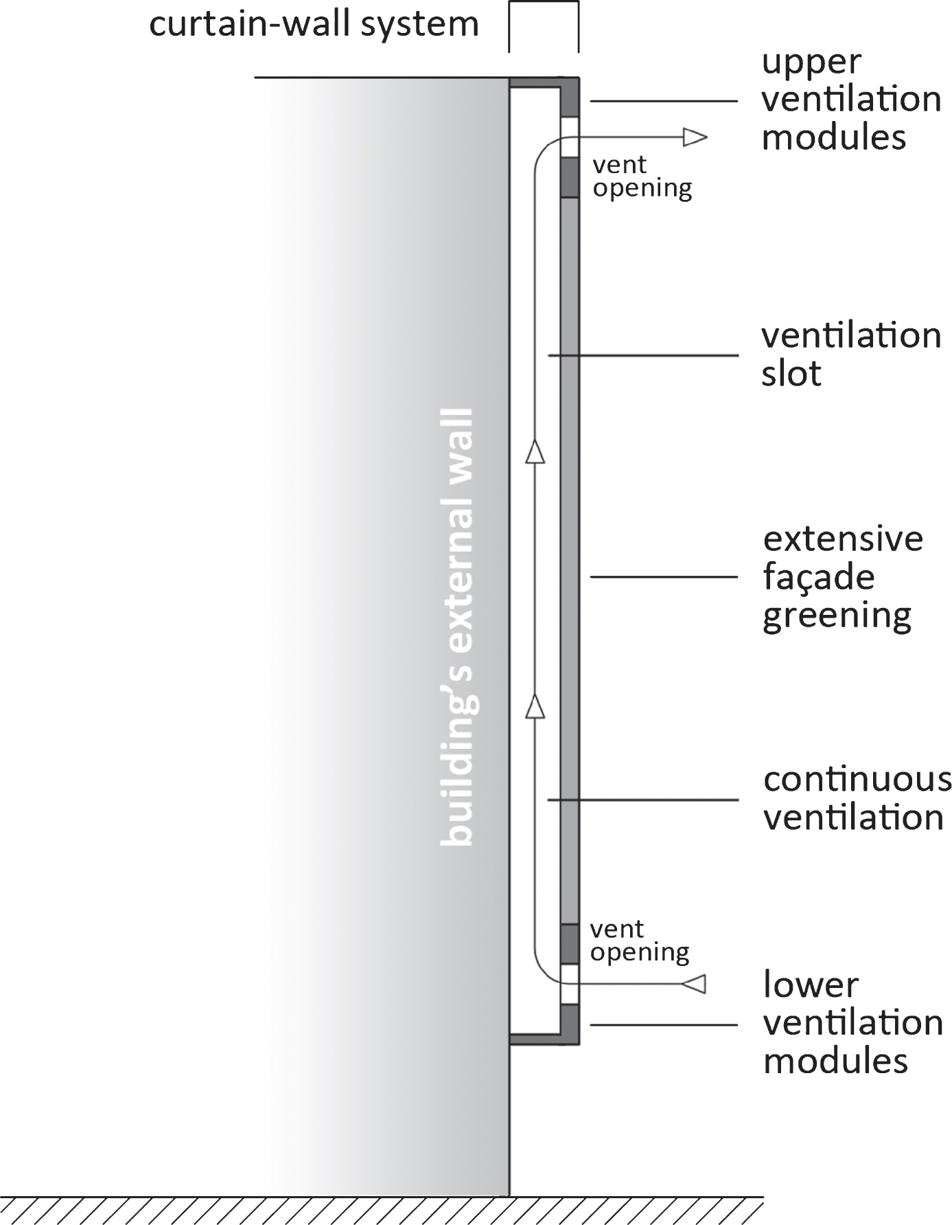
The basic concept behind the façade design is an adaptable curtain-wall system (related to the segmentation of the building surfaces), ensuring continuous air circulation in the slot between the façade and the outer building wall via ventilation modules fitted above and below. It can also be combined with surface greening (Fig. 3).
Fig.3
Basic concept of the façade design.
Specific research in energy and resource saving sources inspired by nature leads to animal constructions, e.g. anthills, prairie dog burrows and termite mounds. All of them have a ventilation system based on a natural induced airflow (Nachtigall & Pohl, 2013; Vogel, Ellington Jr. & Kilgore Jr. 1973; Korb, 2003).
After a detailed comparison and evaluation for an implementation on a façade in accordance with the parameters of the basic design defined above, the next section will provide a more in-depth analysis of prairie dog burrows.
2.3.1Prairie dog constructions
The construction of prairie dog burrows is based on saving energy and maximising resources; they have an easy as well as sophisticated system of wind-generated, continuous air circulation.
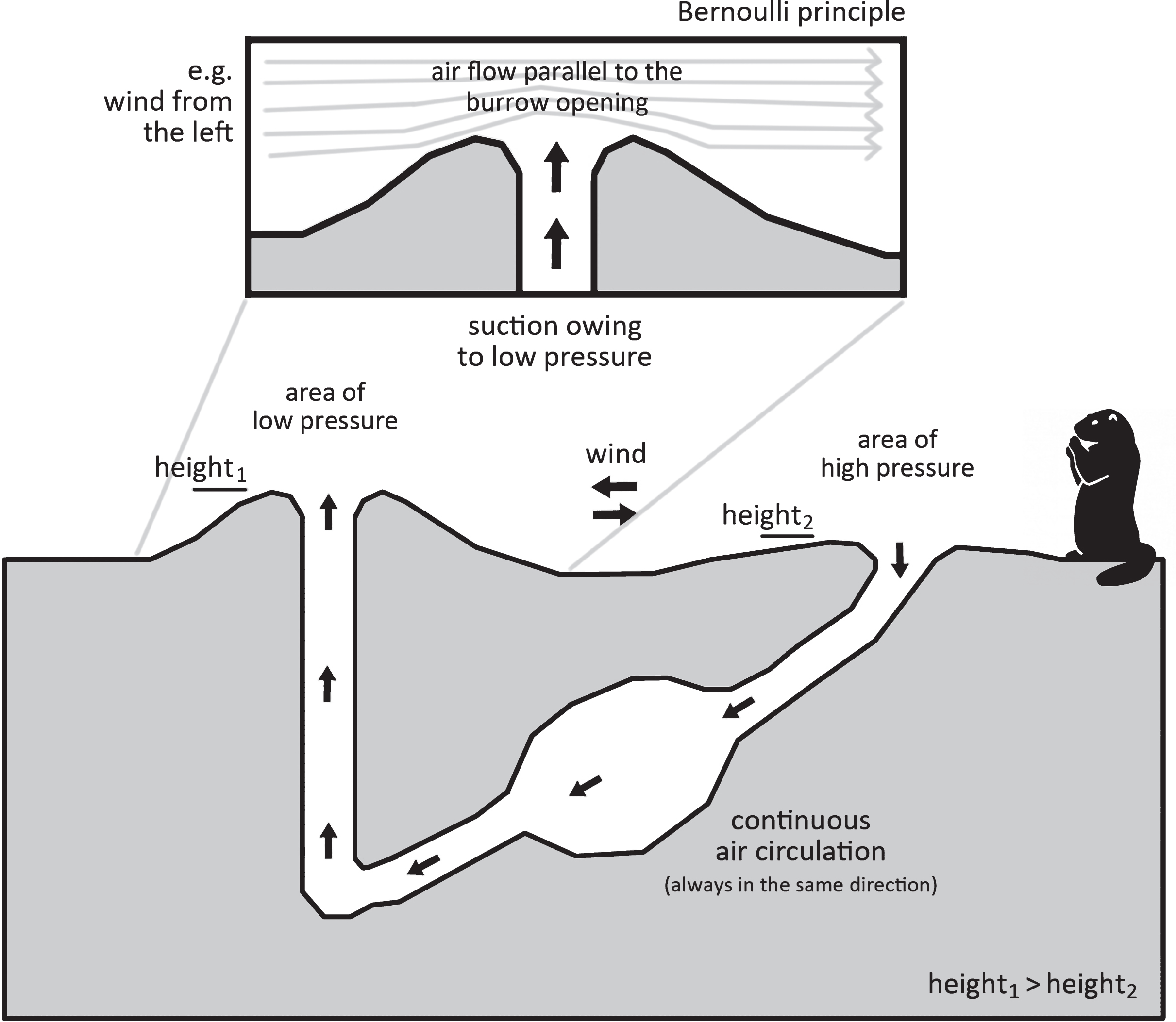
Prairie dogs (Cynomys) create a purpose-built system of passages in their burrows, facilitating cooling of the air supply, especially in summer (Nachtigall, 2002), taking advantage of the Bernoulli principle. By the 18th century, Daniel Bernoulli had already begun to describe the relationship between the flow speed of a fluid (gas or liquid) and its pressure. He discovered that the increase in the speed of a flowing fluid is accompanied by a fall in pressure. To achieve continuous air circulation, prairie dogs build the entrance and exit to their burrows at different heights (Fig. 4). It takes only a light breeze for an area of high pressure to form before the lower opening, thus pulling air through the opening into the burrow. At the higher end of the canal system, on the other hand, there is a low-pressure area that sucks used air out of the burrow. The biologist Steven Vogel and his team were able to demonstrate through measurements that a wind speed of only 0.4 m/s can ventilate the entire burrow within 10 minutes. When the wind speed is 1.2 m/s, this takes only 5 minutes (Vogel, Ellington Jr. & Kilgore Jr. 1973).
Fig.4
The principle of air circulation within a prairie dog burrow (applies to Cynomys ludovicianus). Illustration: Michael J. Paar according to Steven Vogel.
Bernoulli equation for calculating the pressure of perfect incompressible media, Equation (1):
(1)
To determine the structure of the ventilation modules mentioned above (see Fig. 3), further detailed researches should be undertaken.
2.3.2Barnacles
Following the example of the irregular 3D structure, particularly the different heights of prairie dog burrows’ entrances and exits, such self-contained and closely packed, irregular 3D structures are sought out and analysed regarding the use in a façade design. The flow optimized (Thomason et al., 1998), modular growth structure of barnacle cultures is of great interest in that regard.
Barnacles (Balanidae) belong to the crustacean group and are more specifically classed as Cirripedia. These are marine, sessile and immobile creatures that live in water. Charles Darwin had already begun to work extensively with barnacles by the middle of the 19th century. Only greyish-white truncated cone shapes are visible externally. Their limbs have been adapted into cirri (Anderson, 1994). Larvae hatch from barnacle eggs and drift in seawater. As they advance in life, they cement themselves onto hard substrates packed close to one another (Bertness et al., 1992). The subsequent metamorphosis into an adult barnacle involves forming four to eight calcareous plates, resulting in a polygonal base which surrounds their soft body in the form of a truncated cone (Fig. 5).
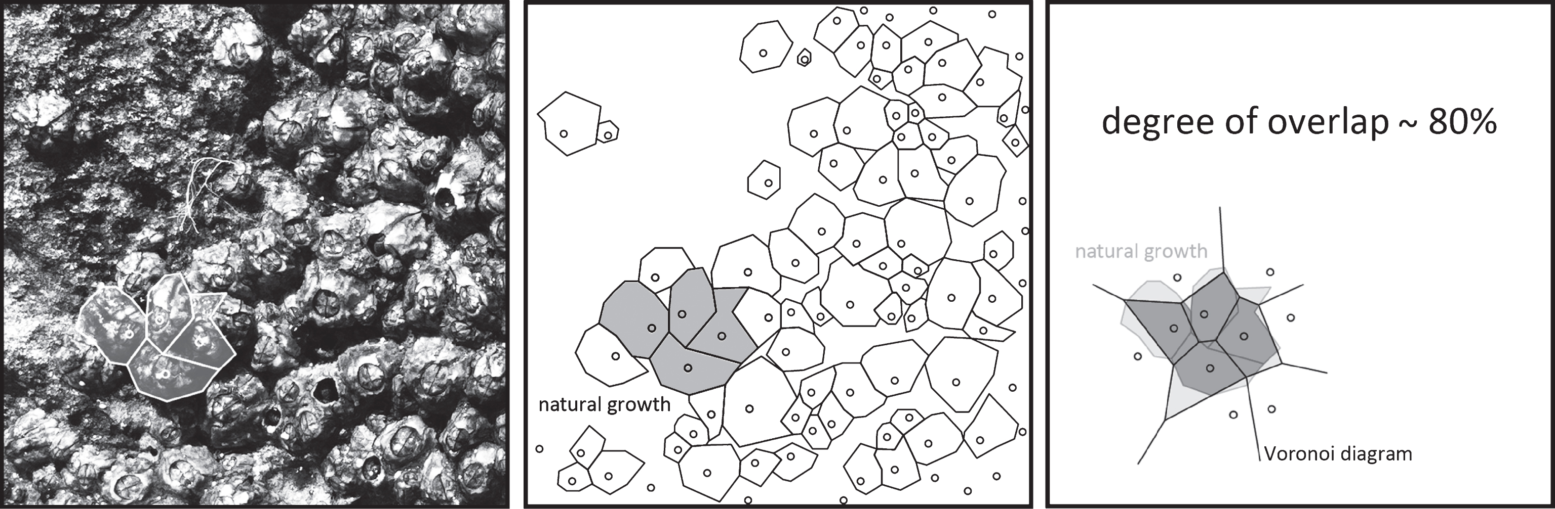
A detailed analysis of the self-contained, closely packed, flow optimized, modular growth structure of barnacle cultures (Semibalanus balanoides) allows us to observe that their surface segmentation is very similar to that of the principle behind a Voronoi diagram. The degree of overlap between the natural growth of barnacle colonies and partitioning the same plane according to the principles of the Voronoi diagram (for the same centres) is approximately 80% (Fig. 6).
Fig.5
The modular growth structure of barnacle cultures (applies to Semibalanus balanoides).
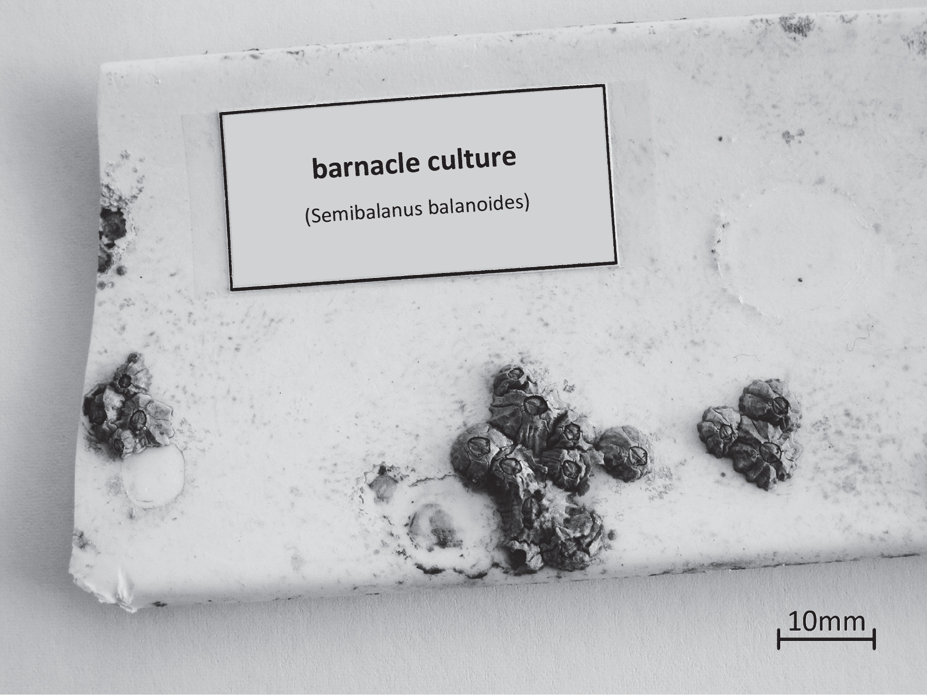
Fig.6
Similarities between the growth of barnacle cultures and the Voronoi diagram.
Voronoi diagrams are employed in a wide variety of scientific fields. The history of research using Voronoi diagrams began in the middle of the 19th century with the Ukrainian mathematician Georgi F. Voronoi. The focus of such research has since been: modelling natural events, mathematical investigations of their geometrical and stochastic properties, and using computers to construct Voronoi diagrams (Aurenhammer, 1991; Zimmer, 2014).
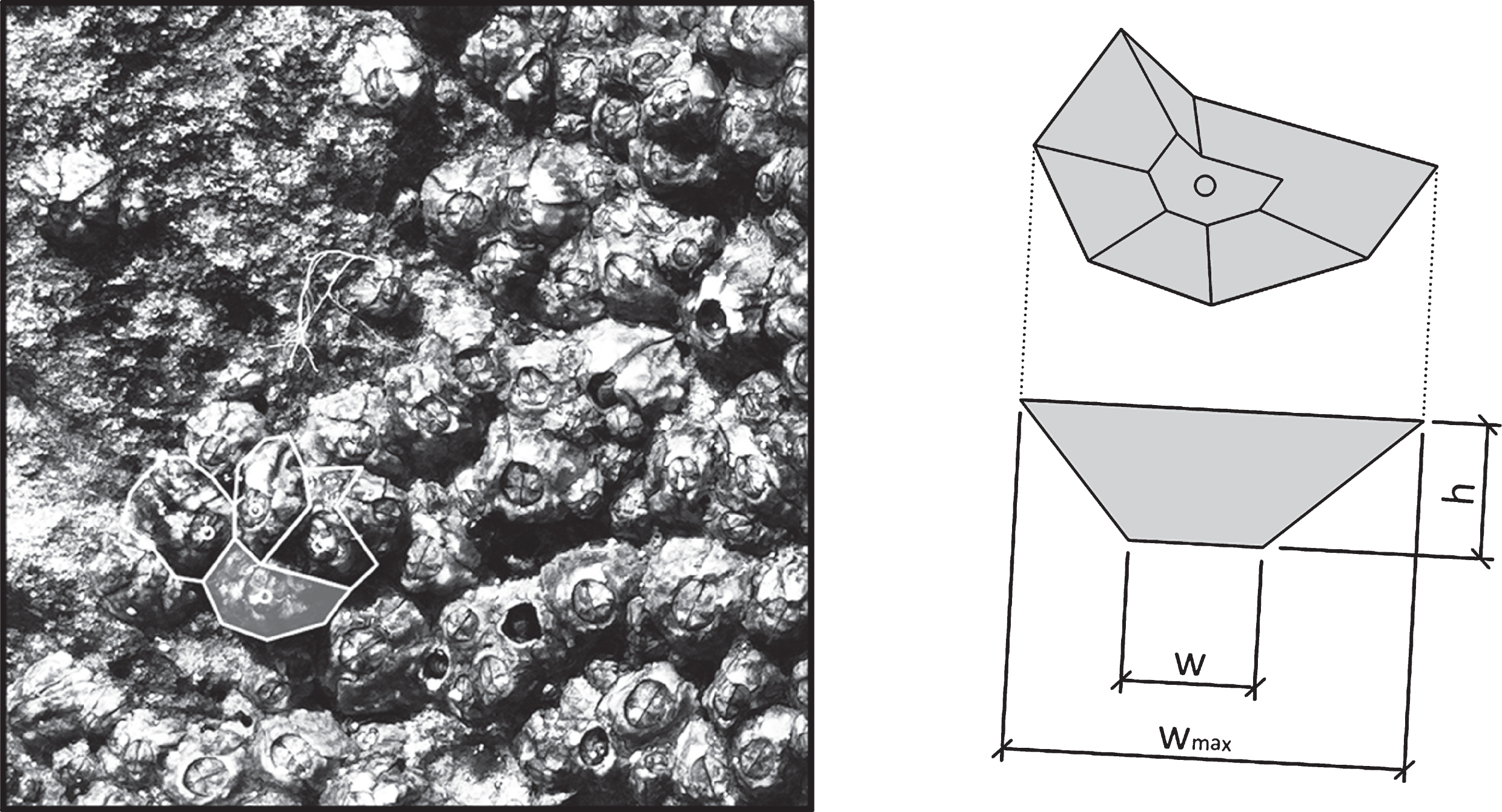
Regarding irregular 3D structures, it has been observed that recurring geometrical proportionalities exist (fieldwork: measurements of 50 barnacles – Semibalanus balanoides, Gulf of Juan, France, summer 2016) in terms of maximum barnacle width and height and the width of the top opening (Fig. 7).
Fig.7
Geometric proportionalities of barnacle shell.
Proportionalities, Equations (2) and (3):
(2)
(3)
3A gradual construction schema
Building on the above findings, the following section presents a gradual schema to construct the adaptable curtain-wall façade design concept aimed at minimising the heat island effect in our cities (Fig. 8).
Fig.8
A gradually construction schema using the example of a square façade surface.
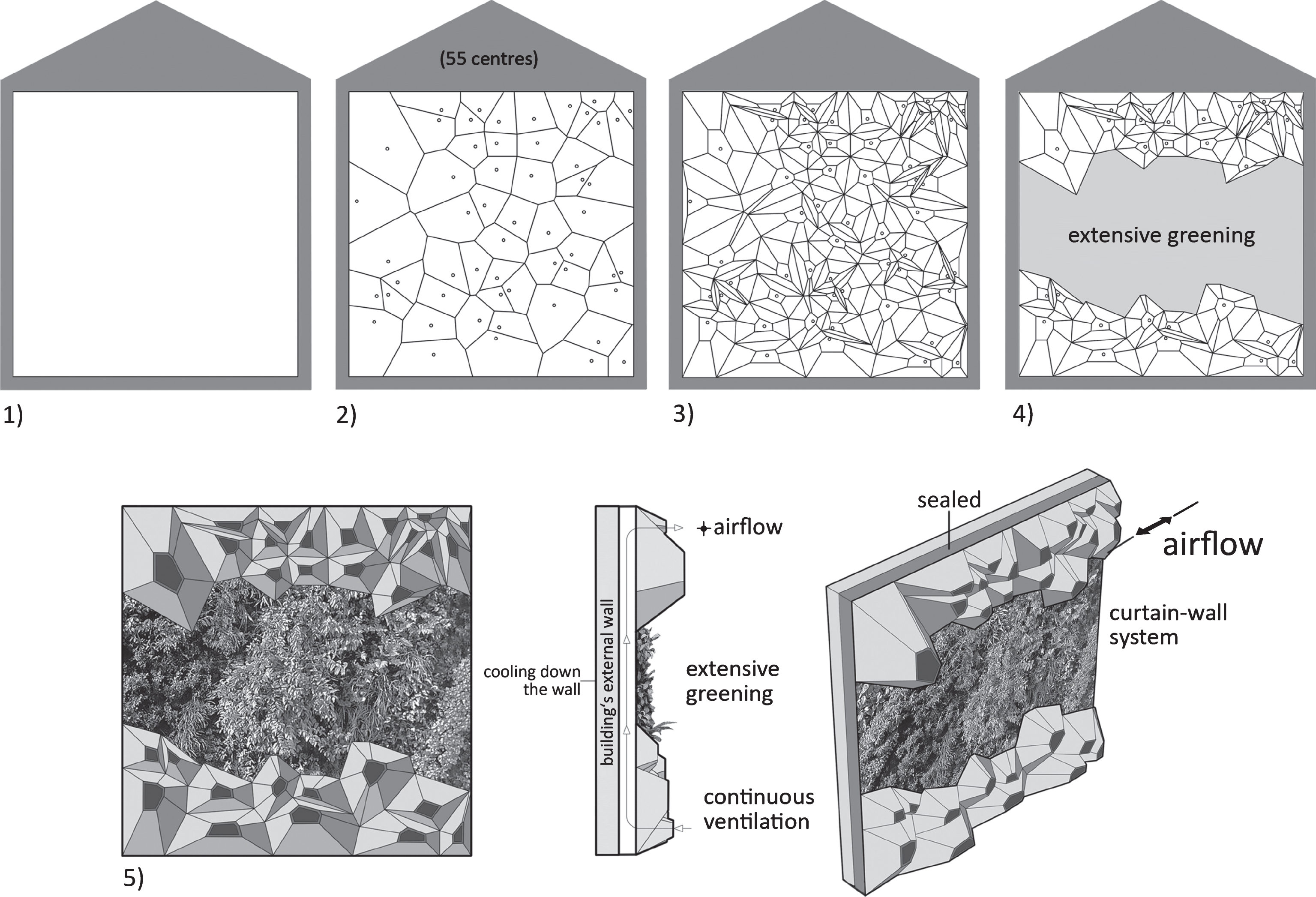
1) Determine the border of the façade surface to which the system is to be attached.
2) Use a random-number generator to determine an arbitrary number of central points on the chosen surface. Use a Voronoi diagram as a basis for structuring the surface in a manner similar to the growth of barnacle colonies (see Fig. 6), as far as the border previously chosen. Additionally, the structuring according to the Voronoi diagram supports – from a designer’s point of view – the appearance of the concept.
3) Three-dimensional extrusion of the self-contained, closely packed structure, taking account of the geometrical proportionalities observed in the case of barnacles (see Fig. 7), thus creating the required ventilation modules. Accordingly, the ventilation modules take the form of irregular, flow optimized hollow truncated cones.
4) Remove the middle section of this three-dimensional structure and insert an extensive greening system that will retain less heat and increase cooling, as discussed above. A reference for the removal are standard values for vent openings in curtain-wall façades, e.g. norm DIN 18516 – Cladding for external walls, ventilated at rear. Thus; a minimum of 200 cm2 vent openings per running façade meter, fitted above and below must be guaranteed.
5) Install the system thus created as a curtain wall on a solid load-bearing structure using knowledge gathered from analysing the construction of prairie dog burrows, used in a vertical arrangement. This should facilitate a wind-generated, continuous air circulation in the ventilation slot between the building’s outer wall and the façade and cool down the wall surface. A thickness of the ventilation slot of at least 2 cm must be guaranteed, also seeDIN 18516.
4Laboratory experiments and initial calculations
4.1Laboratory experiments
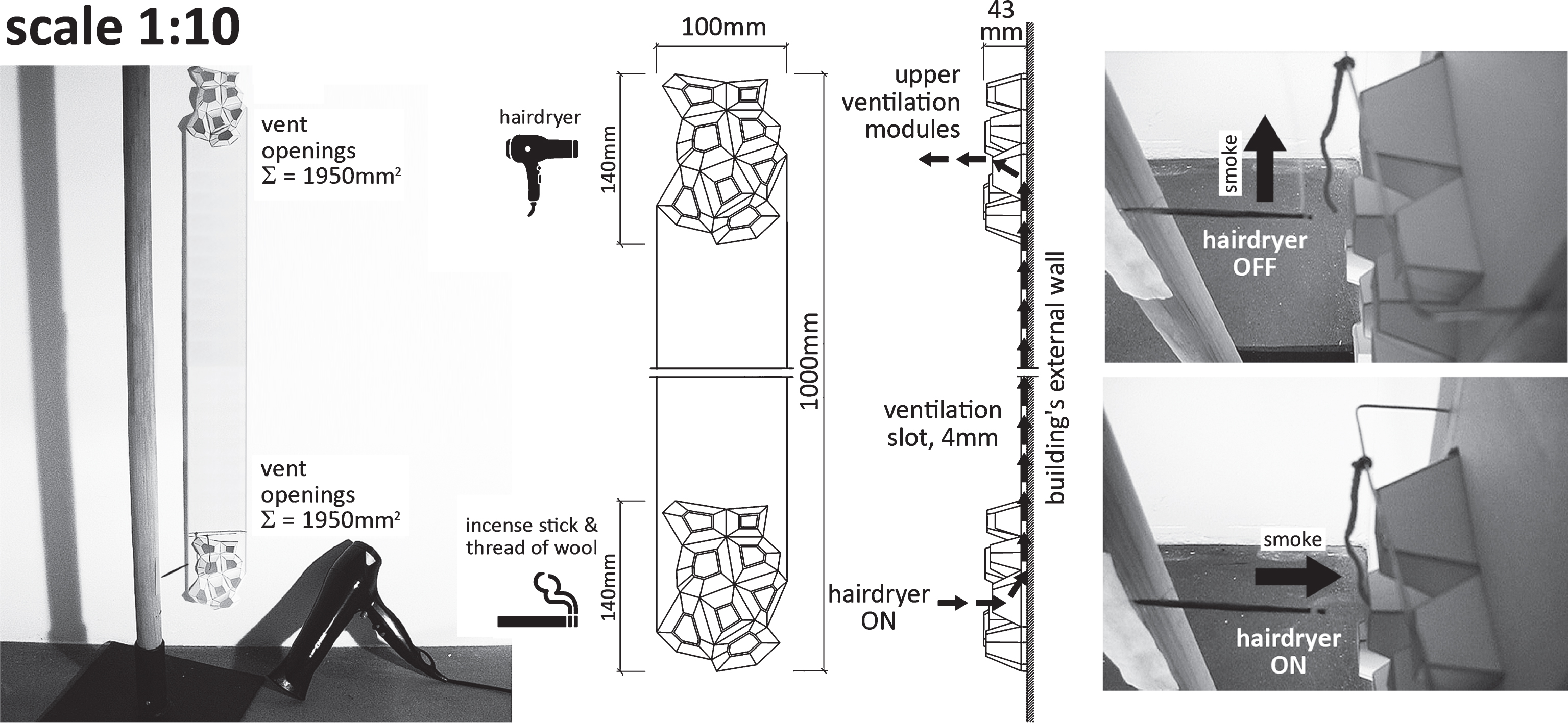
Scaled models, constructed according to the previous explained schema, of one running meter of the façade design concept built out of cardboard (scale 1 : 10), resp. sheet metal (scale 1 : 2) are used to show wind-generated, continuous air circulation within the ventilation slot between the building’s external wall and the façade. A real size ventilation slot of 40 mm and 200 cm2 vent openings per running façade meter, fitted above and below are defined.
A hairdryer, resp. an axial blower are used on the upper ventilation modules to simulate air masses supplying airflow parallel to the ventilation modules. An incense stick and a thread of wool are positioned in front of the lower ventilation modules to render visible the air circulating within the ventilation slot. Continuous circulation of air rising up from below can be observed immediately after the hairdryer, resp. axial blower is switched on (Figs. 9 and 10).
Fig.9
Set-up for the experiment with scale model 1 : 10.
In the case of a real-life application, it is worth noting here that wind speed, which increases with height (Hupfer & Kuttler, 2005), and the stack effect (McLean & Silver, 2008) can have an additional positive effect on the air circulation occurring in the façade slot.
4.2Initial calculations
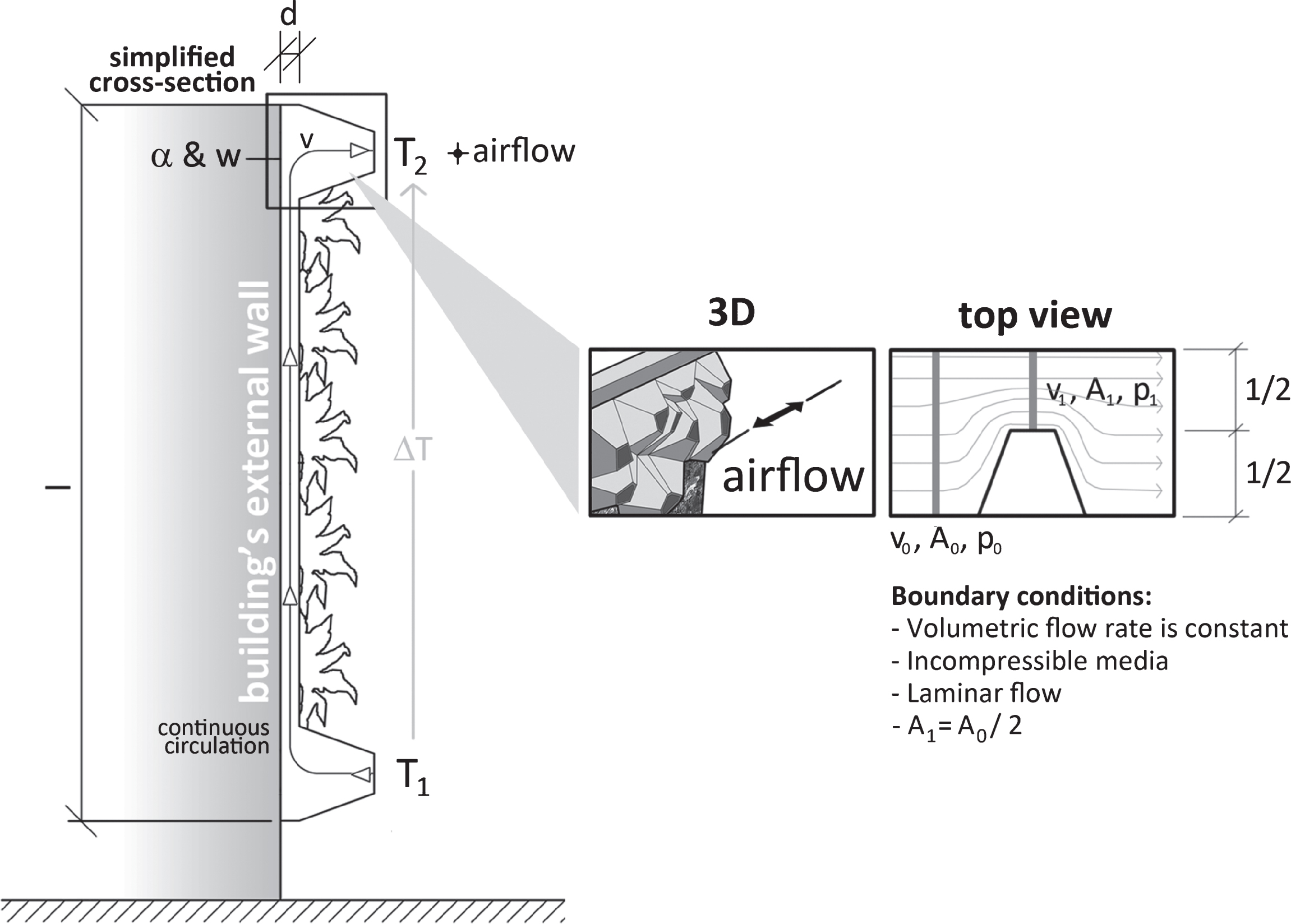
An initial, simplified calculation model is used to illustrate the wind-generated, continuous air circulation within the ventilation slot and the consequent effect of natural convection (Fig. 11). The physical dimensions used for the calculation refer to the above shown scaled models (see Figs. 9 and 10). Temperatures are based on summer conditions in central European cities.
Fig.10
Details of set-up for the experiment with scale model 1 : 2.
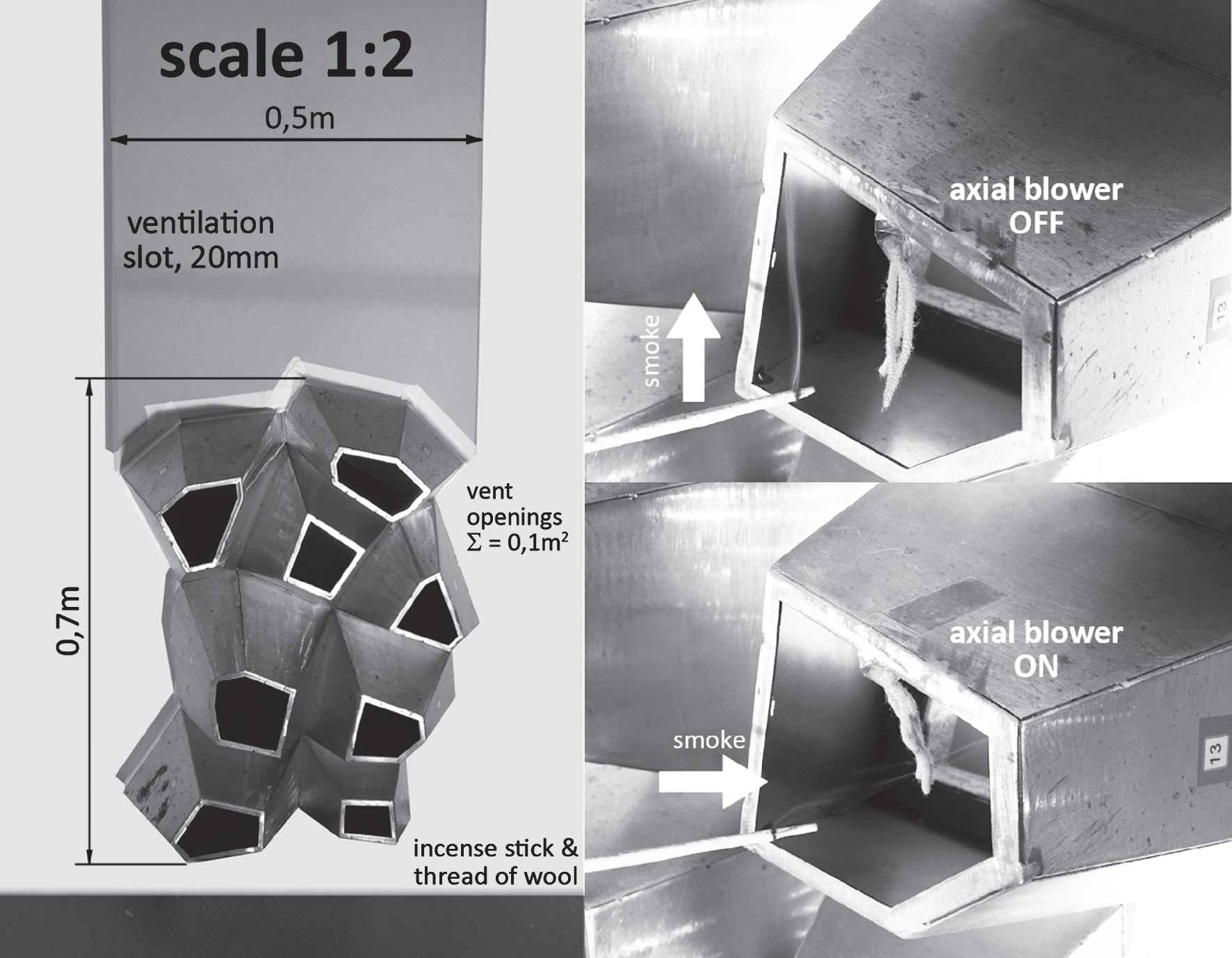
Fig.11
Settings for the calculation model.
Wind-generated laminar flow speed [m/s] above the upper ventilation modules, Equation (4):
(4)
Pressure difference [Pa] above the upper ventilation modules according to Bernoulli (ρ. g. z = 0, negligibly), Equation (5):
(5)
Laminar flow speed [m/s] within the ventilation slot according to Hagen-Poiseuille, Equation (6):
(6)
Heat transfer (natural convection) [W] between the airflow and the building’s external wall, Equation (7):
(7)
α depends on v and l, according to norm VDI 2055 – Thermal insulation of heated and refrigerated operational installations in the industry and in the building services.
v0 and v1 stands for the flow speed of the air. A0 and A1 resp. p0 and p1 are the cross-sections of the air columns and the corresponding air pressures. ρ is the density of air. v, l and d represent the laminar flow speed within the ventilation slot and the length and thickness of the ventilation slot. η, α and w are the viscosity of air, the heat transfer coefficient and the heat transfer between airflow and wall. ΔT and A stand for the temperature differential and the regarded wall surface.
A sample calculation for one running meter of the adaptable façade design concept with the below parameters gives a heat transfer between the airflow and the building’s external wall of 375 W.
Parameters: v0 = 1.4 m/s (according to norm DIN EN ISO 6946 – Building components and building elements. Thermal resistance and thermal transmittance. Calculation method), ρ = 1.2kg/m3 (at 20°C) , η = 0.0000171 N . s/m2 (at 20°C) , l = 10m, d = 0.04m → v = 2.7m/s . α = 15W/m2 . K (standard value according VDI 2055), ΔT = 2 .5°C and A = 10m2.
The flow speed v = 2.7 m/s within the ventilation slot is faster than in conventional ventilated façades; here speed values between 0.15 m/s and 1.0 m/s are common (Häupl, 2008). Thus, the surface temperature of the outer wall of the building may can reduced more efficiently. The effect of cooling mainly depends on the environmental conditions – wind velocity and the temperature differential between lower and upper ventilation modules.
5Conclusion
The findings of the laboratory experiments with the scaled models of one running meter of the adaptable façade design concept and the initial, simplified calculations let us assume that its use can enhance the speed of the continuous airflow within the ventilation slot. That would imply that a higher amount of air could flow through the ventilation slot and the surface temperature of the outer building wall could be reduced more efficiently. Combined with the additional natural cooling effect of façade greening, it may represent a natural approach towards minimising the heat island effect in our cities, as hypothesised in the introduction to this paper.
To verify the actual effect of the concept on the heat island effect and reductions in energy requirements and greenhouse gas emissions associated with cooling buildings artificially, further measurements on a 1 : 1 façade model with integrated greening and a detailed computational fluid dynamics simulation are absolutely relevant. Owing to the higher flow speed, noise measurements are required as well.
Adding further methods to intensifying the cooling of the building’s outer wall could be interesting. Those might include special circulation channels within the façade’s structure, the use of “wind catchers” in the area of the upper ventilation modules, or introducing cooler air masses from lower strata. To act on special environmental conditions, temporary adjustable ventilation, e.g. barnacle-like flaps integrated within the ventilation modules, could be considered as well.
References
1 | Anderson D. T. ((1994) ). Barnacles: Structure, function, development and evolution London: Chapman & Hall. |
2 | Aurenhammer F. ((1991) ). Voronoi diagrams– a survey of a fundamental geometric data structure. ACM Computing Surveys Journal, 23: (3), 345–405. doi: 10.1145/116873.116880 |
3 | Bass B , Martens R , & Alcazar S. S. ((2008) ). Roof–envelope ratio impact on roof green energy performance. Urban Ecosystems Journal, 11: (4), 399–408. doi: 10.1007/s11252-008-0053-z |
4 | Bertness M. D , et al. ((1992) ). Components of recruitment in populations of the acorn barnacle Semibalanus balanoides (Linnaeus. Building and Environment, 156: (2), 199–215. doi: 10.1016/0022-0981(92)90246-7. |
5 | Eumorfopoulou E. A , & Kontoleon K. J. ((2009) ). Experimental approach to the contribution of plant-covered walls to the thermal behaviour of building envelopes. Building and Environment, 44: (5), 1024–1038 doi: http://dx.doi.org/10.1016/j.buildenv.2008.07.004 |
6 | Gosztonyi S , et al. ((2013) ). BioSkin–Research potentials for biologically inspired energy efficientfacade components and systems. Vienna: bmvit. |
7 | Häupl P. ((2008) ). Bauphysik - Klima. Wärme. Feuchte. Schall:Grundlagen, Anwendungen, Beispiele. Berlin: Ernst & Sohn. |
8 | Howard L. ((1818) ). The climate of deduced from Meteorological observations, made at different placesin the neighbourhood of the metropolis. London: 2: . Vol. |
9 | Hupfer P , & Kuttler W. (eds.) ((2005) ). Witterung und Klima. Eine Einführung in dieMeteorologie und Klimatologie (11th ed.). Wiesbaden: B. G. Teubner Verlag. |
10 | Kamal-Chaoui L , & Robert A. ((2009) ). Competitive Cities and Climate Change. OECD Regional DevelopmentWorking Paper. Paris: OECD. |
11 | Köhler M. (ed.) ((2012) ). Handbuch Bauwerksbegrünung. Planung – Konstruktion – Ausführung. Köln: Verlagsgesellschaft Rudolf Müller. |
12 | Korb J. ((2003) ). Thermoregulation and ventilation of termite mounds. The Science of Nature Journal, 90: (5), 212–219. doi: 10.1007/s00114-002-0401-4 |
13 | Krusche P , Althaus D , & Gabriel I. ((1982) ). Ökologisches Bauen. Gütersloh: Bauverlag. |
14 | Landsberg H. E. ((1981) ). The Urban Climate. New York: Academic Press. |
15 | McLean W , & Silver P. ((2008) ). Introduction to Architectural Technology. London: Laurence King Publishers. |
16 | Minke G. ((2010) ). Dächer begrünen – einfach und wirkungsvoll. Planung, Ausführungshinweise und Praxistipps (4th ed.). Staufen beiFreiburg: Ökobuch Verlag. |
17 | Minke G , & Witter G. ((1982) ). Häuser mit grünem Pelz – ein Handbuch zur Hausbegrünung. Frankfurt: Verlag D. Fricke. |
18 | Nachtigall W. ((2002) ). Bionik. Grundlagen und Beispiele für Ingenieure und Naturwissenschaftler (2nd ed.). Berlin: Springer-Verlag. |
19 | Nachtigall W , & Pohl G. ((2013) ). Bau-Bionik. Natur – Analogien – Technik (2nd ed.). Berlin: Springer-Verlag. |
20 | Pawlyn M. ((2011) ). Biomimicry in Architecture. London: RIBA Publishing. |
21 | Rawlings A. E , Bramble J. P , & Staniland S. S. ((2012) ). Innovation through imitation: Biomimetic,bioinspired and biokleptic research. Soft Matter Journal, 8: (25), 6675–6679. doi: 10.1039/C2SM25385B |
22 | Riviere P , et al. ((2008) ). Preparatory study on the environmental performance of residential roomconditioning appliances (airco and ventilation). Draft report for the European Commission. |
23 | Santamouris M. (ed.) ((2011) ). Energy and Climate in the Urban Built Environment. London: Routledge. |
24 | Thomason J. C , et al. ((1998) ). Hydrodynamic consequences ofbarnacle colonization. Recruitment, Colonization and Physical-Chemical Forcing in Marine Biological Systems, 132: , 191–201. doi: 10.1007/978-94-017-2864-5_16 |
25 | Vincent J. F. V , et al. ((2006) ). Biomimetics: Its practice andtheory. Journal of the Royal Society Interface, 3: (9), 471–482. doi: 10.1098/rsif.2006.0127 |
26 | Vogel S , Ellington C. Jr , & Kilgore D. Jr. ((1973) ). Wind-induced ventilation of the burrow of the prairie-dog,Cynomys ludovicianus. Journal of Comparative Physiology, 85: (1), 1–14. doi: 10.1007/BF00694136 |
27 | Wong N. H , et al. ((2010) ). Thermal evaluation of vertical greenery systems for building walls. Journal of Building and Environment, 45: (3), 663–672. doi: http://dx.doi.org/10.1016/j.buildenv.2009.08.005 |
28 | Zimmer H. ((2014) ). Optimization of 3D Models for Fabrication. Aachen: Shaker Verlag. |

