
A hybrid data-driven BSDF model to predict light transmission through complex fenestration systems including high incident directions
Abstract
The transmission and distribution of light through Complex Fenestration Systems (CFSs) impacts visual comfort, solar gains and the overall energy performance of buildings. For most fenestration, scattering of light can be approximated as the optical property of a thin surface, the Bidirectional Scattering Distribution Function (BSDF). It is modelled in simulation software to replicate the optical behaviour of materials and surface finishes. Data-driven BSDF models are a generic means to model the irregular scattering by CFS employing measured or computed data sets. Even though measurements are preferred due to the realistic values they provide it is not always possible to measure the light scatter in all incident directions. In contrast, numerical simulations have virtually no limitations; however, at the cost of lower reliability. A hybrid approach, combining both, was therefore proposed. The BSDF of a CFS was measured for incident elevation angles from 0° to 60°. For incident elevation angles from 0° to 85°, the BSDF of the sample was computed. The BSDF acquired by both techniques in the overlapping range of directions between 0° to 60° was compared and revealed good qualitative accordance. The variance of the direct-hemispherical reflection and transmission based on the two techniques was between 3% and 28%. A hybrid data set was then generated, utilizing measurements where possible and simulations where instrumentation could not provide reliable data. A data-driven model based on this data set was implemented in simulation software. This hybrid model was tested by comparison with the geometrical model of the sample and measurements. The hybrid approach to BSDF modelling shall support the utilization of BSDF models based on measured data by selectively overcoming the lack of reliable measured or extrapolated data.
1Introduction
Complex Fenestration Systems improve visual comfort, particularly in offices by excluding sun-light and evenly distributing daylight across the occupied zone. Negative effects of excessive daylight exposure in the building perimeter, such as glare are avoided (Kazanasmaz et al., 2016; Mohanty, Yang, & Wittkopf, 2012). The even supply of daylight can help to reduce the operation of artificial lighting, and the related demand for electrical energy.
The development, optimization and successful application of CFSs require to characterise their optical properties, particularly the light scattering. Planning decisions as well as product design and optimization are often supported by computational simulations. Extensions for simulation software can predict the light propagation through complex optical systems such as CFSs based on explicit geometric optical modelling (Bauer & Wittkopf, 2016; Grobe, Müllner, & Meyer, 2015; Schregle, Grobe, & Wittkopf, 2016) but further add to the already high complexity of building-scale simulations. This can be avoided with the implicit modelling of CFSs by their resulting light scattering. As a surface property, the Bidirectional Scattering Distribution Function evaluates to luminous coefficients; describing scattering for any pair of incident and outgoing directions (Ward, Mistrick, Lee, McNeil, & Jonsson, 2011).
Emanating from assumptions on common optical characteristics of particular classes of reflective or transmissive surfaces, BSDF models are implemented in simulation software replicating regular diffuse and specular transmission or reflections (Kurt & Edwards, 2009; Montes & Ureña, 2012; Ngan, Durand, & Matusik, 2005; Renhorn & Boreman, 2008; Westin, Li, & Torrance, 2004), applying principles of geometric optics e.g. in micro-facet theory to reflection (Cook & Torrance, 1981) (Ashikmin, Premože, & Shirley, 2000; He et al., 1991; Torrance & Sparrow, 1967) and transmission (Walter et al., 2007). Empirical models aim at the accurate replication of measurements, avoiding the complexity of relating these to underlying principles such as surface parameters. Similar to their analytical counter-parts, they are valid for a particular class of reflective or transmissive surface (Geisler-Moroder & Dür, 2010; Lafortune et al., 1997; Phong, 1975). Parameters are found directly as measurable optical properties such as diffuse and specular reflection or transmission, or by fitting the entire model to observation data (Ward, 1992).
Both analytical and empirical BSDF models emanate from prior assumptions of characteristics in the scattering distributions, which are gradually changing with varying incident and outgoing directions (Noback, Grobe, & Wittkopf, 2016). The irregular BSDF of CFSs challenges such approaches and led to the development of custom models for particular CFSs (Reinhart & Andersen, 2009). To overcome the lack of a general analytical or empirical description of any CFS, data-driven models allow to make direct use of BSDF data in simulations (Matusik et al., 2003; Tian et al., 2013). Interpolation techniques compute the BSDF for any pair of incident and outgoing directions from discrete sets of measured data (Bonneel et al., 2011). Data-reduction techniques are employed to allow storing and sharing of the tabular data (Ward, Kurt, & Bonneel, 2015), or to compress it by factorization or employing wavelets (Claustres, Paulin, & Boucher, 2003; Kautz & McCool, 1999; Rusinkiewicz, 1998).
The acquisition of BSDF can be performed by imaging and scanning goniophotometers. An example of imaging goniophotometers are systems utilizing imaging spheres (Yu et al., 2012). They comprise a highly reflective hemispherical mirror onto which scattered light is directed and from where a digital camera collects the information. Thus, these systems have a very short acquisition time. Alternates to imaging spheres are scanning goniophotometers (Andersen et al., 2005; Andersen & Scartezzini, 2005; Andersen & de Boer, 2006; Leloup et al., 2008). They sequentially capture scattered light for different outgoing directions by mechanical movement of a detector. The technique leads to typically longer acquisition times, but allows for a higher dynamic range and configurable directional resolution. Regardless of the chosen method, the measurements of light scattering characteristics when the sample is illuminated close to grazing angles is always a great challenge. One of the fundamental problems is the light spot size whose diameter is inverse proportional to the cosine of the light incident angle and becomes infinitely large. That is of high interest for Daylight Redirecting Components (DRC) for certain locations on the globe where the sun in the zenith position is close to 90 degrees. The other issue can be caused by the mechanics of the measurement systems. Particularly for large samples prevailing in the field of building sciences, measurements of the BSDF for directions close to grazing are impacted by shadowing and edge effects.
Another way to determine light scattering characteristics is the usage of computational simulation, such as ray-tracing, employing models of the sample’s geometry and surface properties. Despite the progress in the accuracy of numerical simulation software, its results always reflect an assumed, idealised geometry, which can significantly deviate from samples due to unknown effects e.g. caused by manufacturing or bending. Even if they seem marginally small their influence on the whole light redirection system might be significant (Grobe et al., 2015). While measurements are preferred by researchers aiming at realistic values, they are constraint by the measurement geometries of the employed instrumentation. Reliable extrapolation techniques are not available due to the irregularity of the BSDF. Computational simulation is not limited by such constraints at the cost of lower realism. Therefore, in this work we propose to combine the advantages of both and comprise the measured BSDF values with values calculated based on geometrical simulations
2Methods
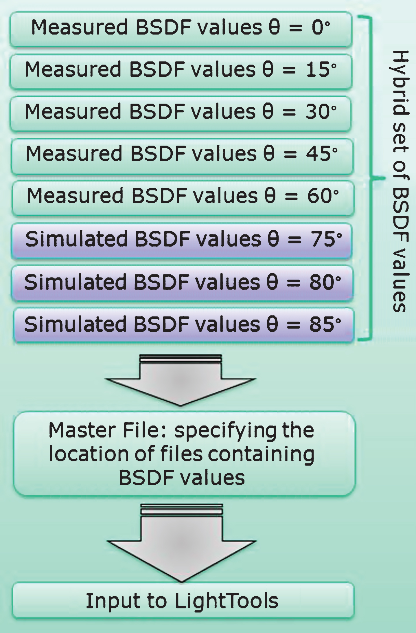
Figure 1 schematically presents a combination of the measured and simulated data. Data obtained by the goniometric measurements are recorded for irregular directions, while the input to simulations is supposed to be in regular grid. Therefore, the measured data was resampled to a regular, tabular format prior to the composition of the hybrid model.
Fig.1
Combination of BSDF data from measurements and simulations into one hybrid set of data.
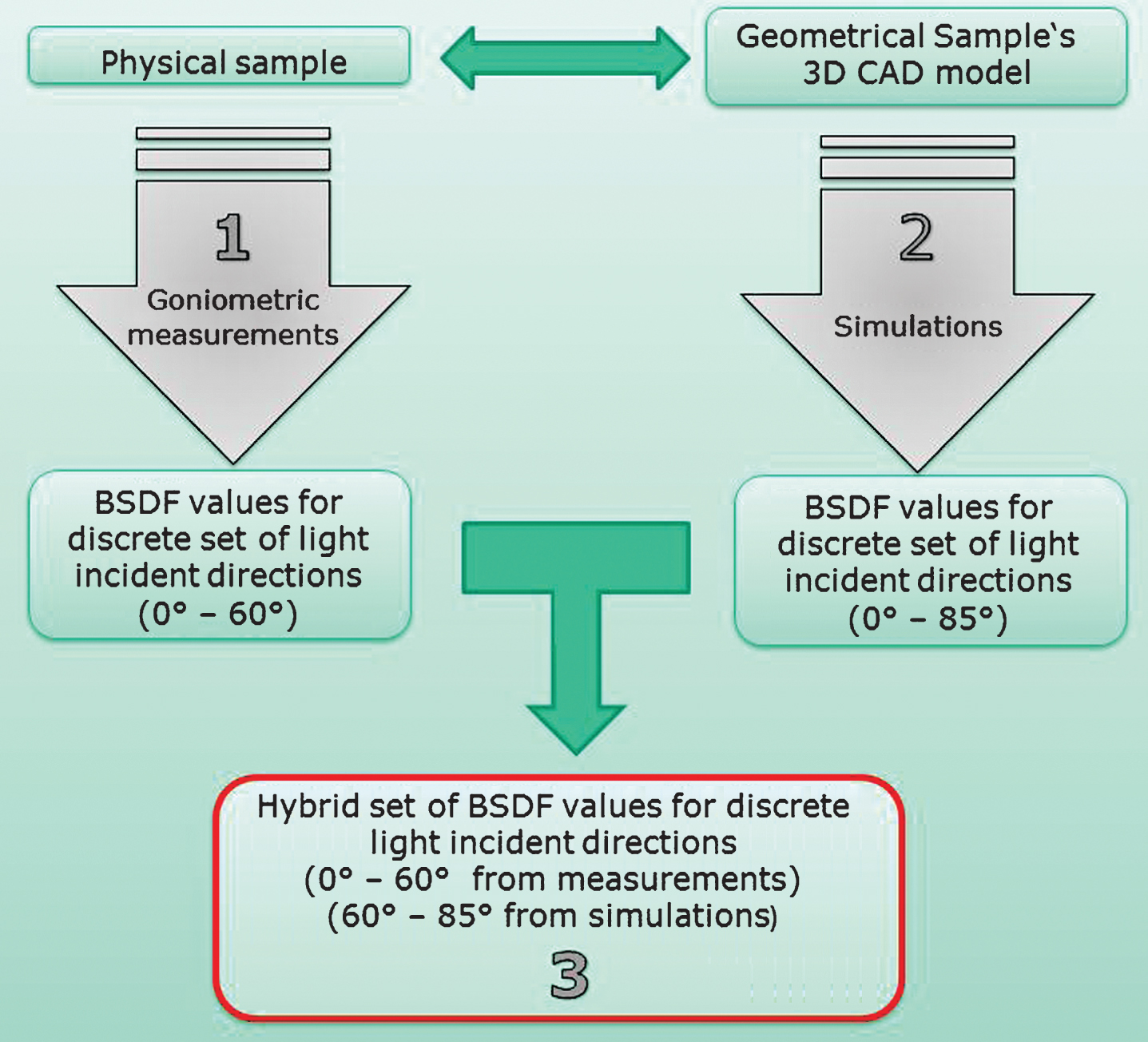
The hybrid set of BSDF (hBSDF) values, as presented in the bottom block of Fig. 1, was implemented in the simulation software. Consequently, the light scatter simulations based on hBSDF values were conducted. Such an approach featuring the advantages of both (data driven and computationally generated BSDF values) has, to the best of our knowledge, not been reported yet.
2.1Light scattering sample
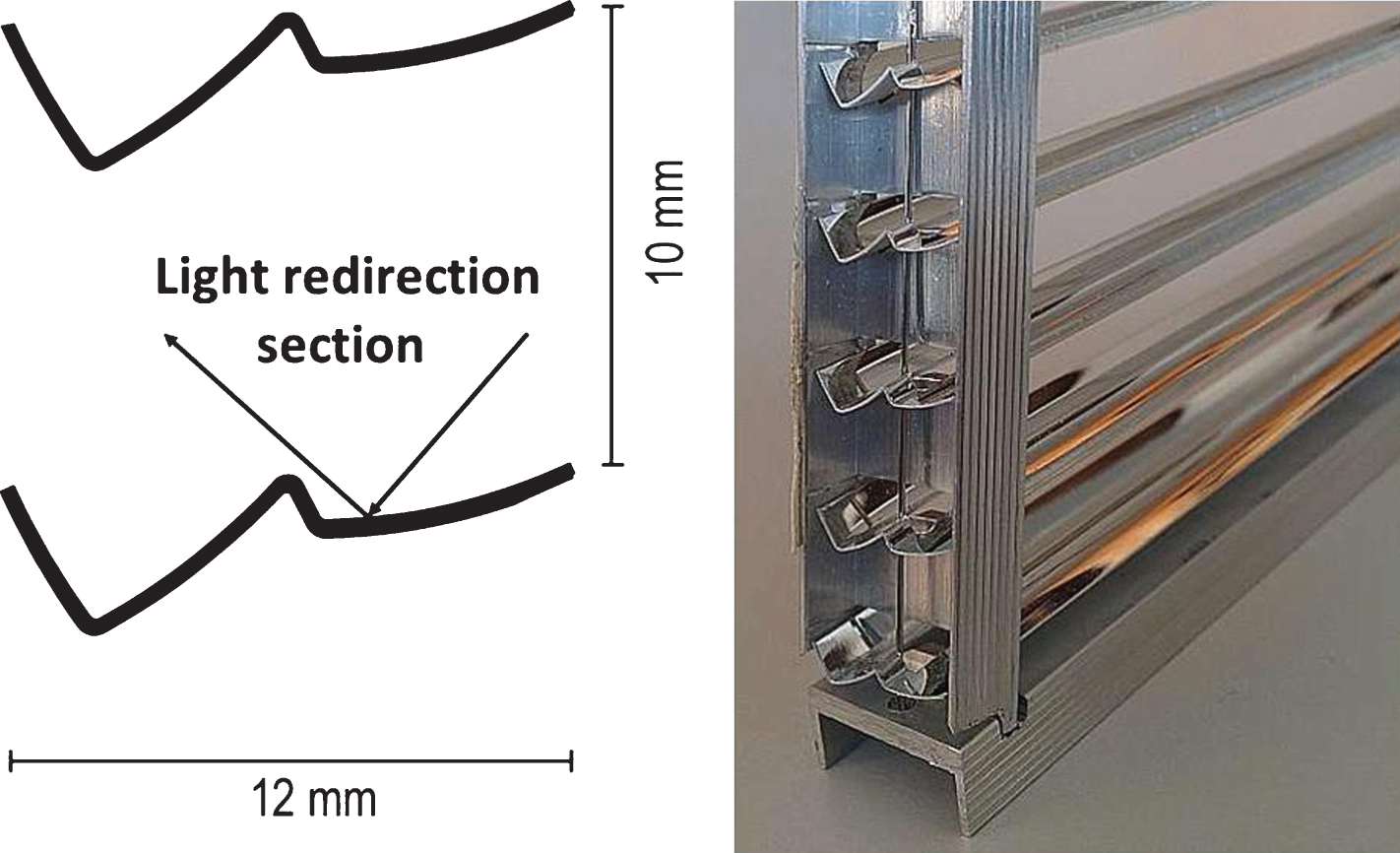
A sample of a retroreflecting DRC, based on the principles of geometric optics, was acquired by the manufacturer together with the corresponding construction drawings. The sample was chosen due to its large geometry and periodic structure as both features are a typical problem in BSDF modelling. The measured sample consists of 39 parallel periodically placed slats held in position by an aluminium frame. The slats have a mirror-like top, and are coated with a white paint on the bottom surface. Figure 2 shows a 2D profile (on the left side) together with a picture of part of the sample (right side). The 2D profile, as provided by the supplier, was used to conduct simulations, whereas the sample presented on right side of Fig. 2 was measured.
Fig.2
The sample, Retro LuxTherm12, was provided on request by RetroSolar, Kirn, Germany. The design by Helmut Köster is patented.
2.2BSDF measurements - 1
The measurements of light scattering were conducted employing a scanning goniophotometer presented in Fig. 3 (Apian-Bennewitz, 2010; Krehel, Kaempf, & Wittkopf, 2015).
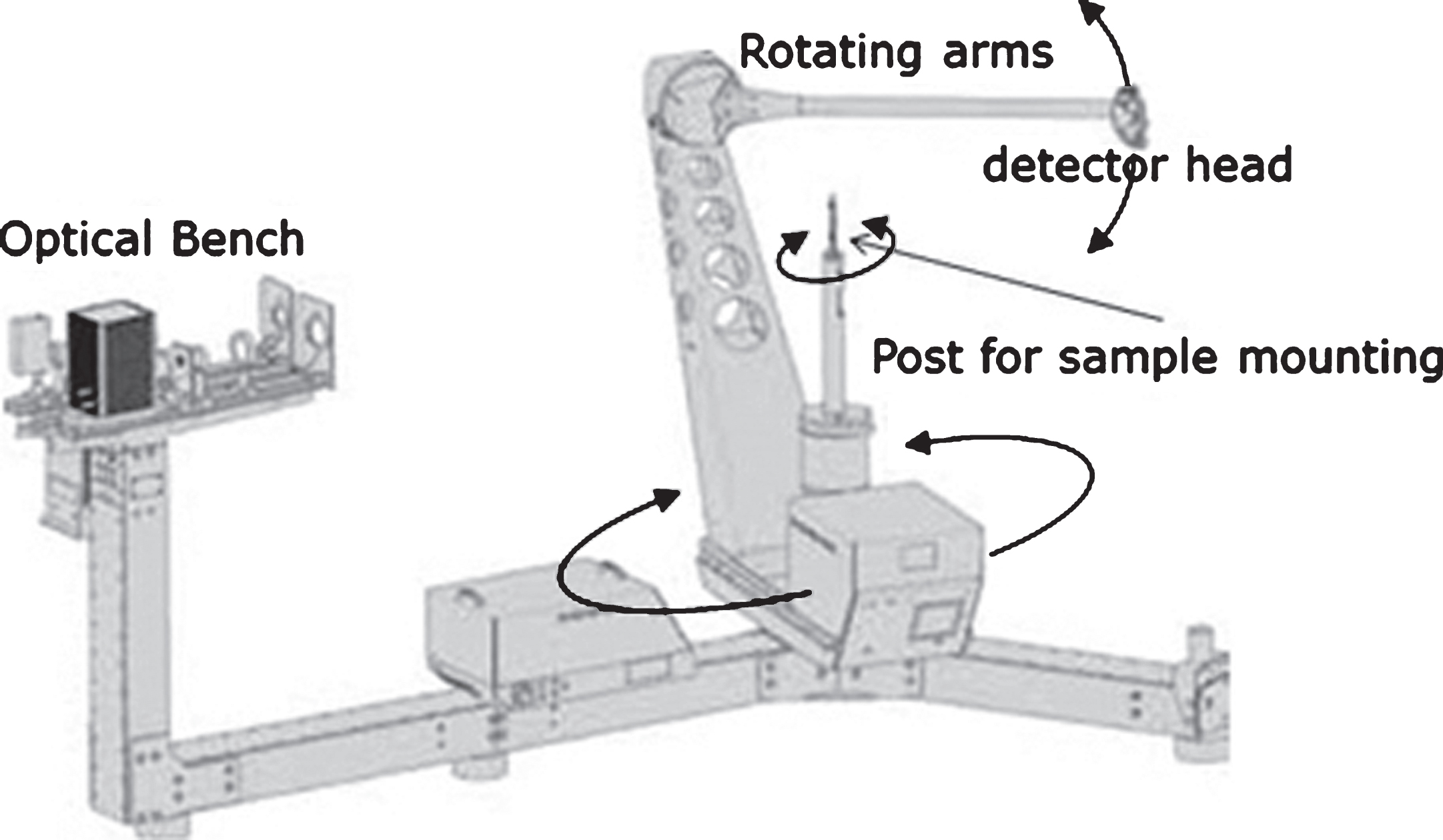
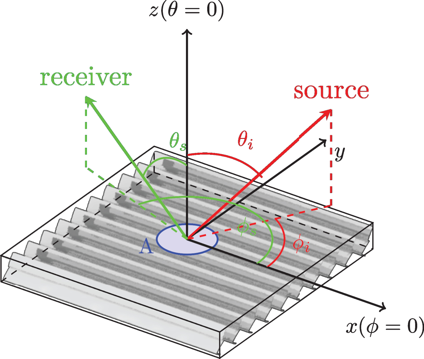
It achieves high directional resolutions in areas of interest by means of refined peak scanning. A Halogen lamp with bandpass filter blocking near infrared light of wavelengths longer than 700 nm was employed as a light source. Light was collimated, the optical setup resulting in a sampling aperture of 70 mm. The diameter in this range results in a coverage of 6-7 light redirection slats which is a prerequisite for BSDF measurements. The measurements were conducted for the following light incident directions: ThetaIn (θi) (altitude) = 0° to 60° with 15° increment for one PhiIn (ϕi) (azimuth) orientations = 0° resulting in total number of five incident directions. The coordinate system is schematically presented in Fig. 4.
Fig.4
Angular coordinate system describing directions to light source θi, ϕi and receiver θs, ϕs as used in the parametrization of the BSDF.
In configurations where the light scatter could not be measured, for instance for retro reflection at θi = 0°, the BSDF values were interpolated with the software provided with the apparatus.
2.3Computation of BSDF based on simulations - 2
Based on the geometrical design of the sample the light scatter simulations were conducted in LightTools. LightTools is an optical engineering and design software that allows simulation and analysis of non-imaging optics. The sample was modeled based on its nominal parameters and the light beam parameters were replicated from the light beam at the scanning goniophotometer (d = 70 mm with 1° of beam divergence). The results obtained from geometrical based simulations were utilized in order to obtain BSDF values. The computation was performed according to Equation 1 (Grobe et al. 2015):
(1)
Where: DSF – Differential Scattering Function, Pi – power of unobstructed beam, Es,n – irradiance on sensor s for measurement n.
The BSDF was computed for the following set of incident directions: θi = 0°–75° with 15° increment and additionally 80° and 85°; all with ϕi orientation equal to zero. The BSDF values obtained for the range 0° to 60° were used for comparison with the measurements, while the additional angles were used as supplemental ones to create a hybrid set of BSDF values comprising measured and simulated ones – as schematically presented in the red block of Fig. 1.
2.4Hybrid BSDF model in LightTools –3
To use the BSDF values in LightTools for light scatter modelling they need to be structured as presented Fig. 5. Since the measured data were recorded for irregular directions the data were binned into the tabular grid (the acceptable format by LightTools). Light scatter data were embedded in text files with spherical coordinates where one file represents data for a given light incident direction. Additionally, one master file indicates all associated data files. Furthermore, a file with specified values of direct-hemispherical reflectance and transmittance as a function of light incidents angles was specified. Once the set of data is implemented in LightTools it performs the linear interpolation of the light scatter in between the input data on the fly.
Fig.5
Diagram illustrating the approach of inputting the tabular hBSDF scatter data into LightTools.
3Results and discussion
At first the comparison of measured and simulated data is presented. Regardless expected discrepancies between the geometrical simulations and measured data the results should be compared to assess if they remain in the same order of magnitude. Only when the data do not exhibit very large discrepancies the measured BSDF values can be combined with simulated ones and utilized to create hybrid set of BSDF values. In Fig. 6 BSDF profiles in the scatter plane are plotted. The BSDF values were plotted for each incident direction, for which they had been either measured or computed (i.e. θs 0°, 15°, 30°, 45° and 60°). The horizontal axis presents the outgoing angles ranging from θs −90° to 270°. Values ranging from θs −90° to 90° represent the intensity slice, whereas values from θs 90° to 270° represent data from the transmission hemisphere. In Fig. 6 a) on the reflection side the diffuse signal from measurements corresponds well to simulations; however, one missing peak can be noticed. On the transmission side, on the other hand, the peaks correspond well to each other but the difference in the diffuse light could be observed. Figure 6 b) and c) presents the BSDF profile of light scatter for the light incident angles θi = 15° and θi = 30°. On the side representing reflection (θs −90° to 90°) the most prominent peak of the simulations is systematically shifted about 5° towards the negative part on the horizontal axis. The missing peak in Fig. 6 a) as well as the shift of the peaks in Fig. 6 b) and c) can be explained by different tilt angles of slats between the geometrical design and in the physical sample. Even a small difference in the slats positioning significantly influences the light redirection. Therefore, the missing peak in Fig. 6 a) is not visible in measured values. However, on the transmission side of Fig. 6 a) the measurements exhibit an elevated signal in the range from θs 180° to 270° which originates from the redirected peak from the reflection side. The same tilt of the slats in the samples is responsible for the peak shift in Fig. b) and c). When examining the peaks positions on the transmission side (θs 90° to 270°) the peaks perfectly coincide. They are not redirected by the simulated DRC, hence any discrepancies originating in sample geometry are not introduced.
Fig.6
Comparison of measured and simulated data at ϕi = 0° and following θi: a) 0°, b) 15° c) 30°, d) 45° and e) 60°.
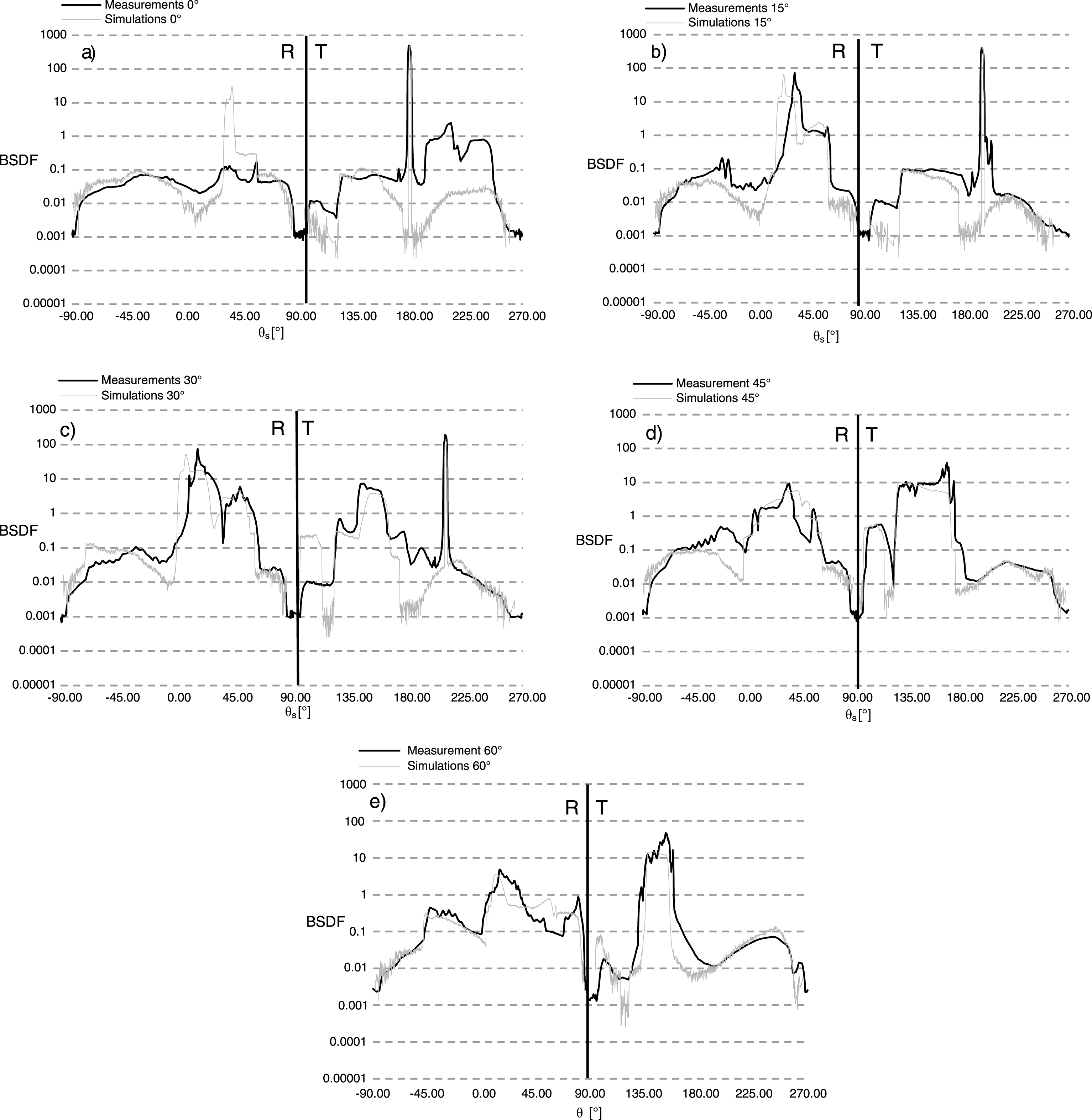
In the reflection part at the light incident direction θi 45° and 60° (i.e. Fig. 6 d) and e)) the shift of the peaks is less significant than in Fig. 6 a) - c). When the sample is illuminated at θi higher then ∼40°, other surfaces start to reflect the light. Thus, the effect of the tilt of the slats is less prominent. Additionally, the values for incident angle θi = 30° on the transmission side are systematically lower. Overall, the diffused parts of the scattered light differ more significantly. However, the part where the light intensity is stronger than 1 exhibited lower differences. Similarly to the work conducted by Grobe et al. a good accordance between computed BSDF and the measurement was found, and the observed discrepancies were as expected (Grobe et al., 2015).
3.1Reflectance and transmittance
Table 1 lists values of reflectance and transmittance for each measured and simulated incident angle. It can be easily observed that the measured reflection values are systematically lower. This systemic discrepancy occurs due to the fact that detector collecting light in the reflection hemisphere, at certain positions, covers the light source. Since the DRC was designed to retroreflect the light this significant amount of the signal had to be interpolated and is thus underestimated. The values for transmission vary randomly. This, as described in the introduction, can originate in the differences between manufactured samples and simulated ones.
Table 1
Comparison of measured and simulated direct-hemispherical reflection and transmission for ϕi = 0°
| θi [°] | Reflection | Transmission | ||||
| Meas. | Sim. | Meas. – Sim.[%] | Meas. | Sim. | Meas. – Sim.[%] | |
| 0 | 0.14 | 0.15 | 5% | 0.821 | 0.8 | 3% |
| 15 | 0.28 | 0.36 | 21% | 0.642 | 0.62 | 4% |
| 30 | 0.51 | 0.55 | 7% | 0.429 | 0.4 | 7% |
| 45 | 0.30 | 0.42 | 28% | 0.47 | 0.54 | 13% |
| 60 | 0.29 | 0.33 | 13% | 0.505 | 0.54 | 6% |
All of the exhibited discrepancies that were discussed above lead to the conclusion that, as stipulated in the introduction, data driven models are always of the best choice when a high degree of realism is to be achieved. Therefore, it is recommended to conduct light scatter simulation based on measured BSDF data.
3.2Hybrid BSDF
In this chapter the hBSDF approach is validated. The light scatter generated by a hBSDF data set is compared with measurements for θi: 15°, 30°, 45°, and presented in Fig. 7 a), b) and c), whereas in Fig. 7 d), e) and f) the hBSDF is compared with geometrical simulations for θi: 75°, 80°, 85°. Both types of the simulations were conducted in LightTools.
Fig.7
Profiles of a light scatter generated for validation of hBSDF simulations. Fig. 7 a), b) and c) compare measured data with simulated data by hBSDF model for ϕi = 0° and the following θi 15°, 30° and 45° respectively. Whereas Fig. 7 d), e) and f) present the comparison of geometrical based simulations with hBSDF at the following θi: a) 75°, b) 80° and c) 85°. The left-hand side of the chart indicated with the letter R represents Reflection, while the right-hand side indicated with the letter T shows Transmission data.
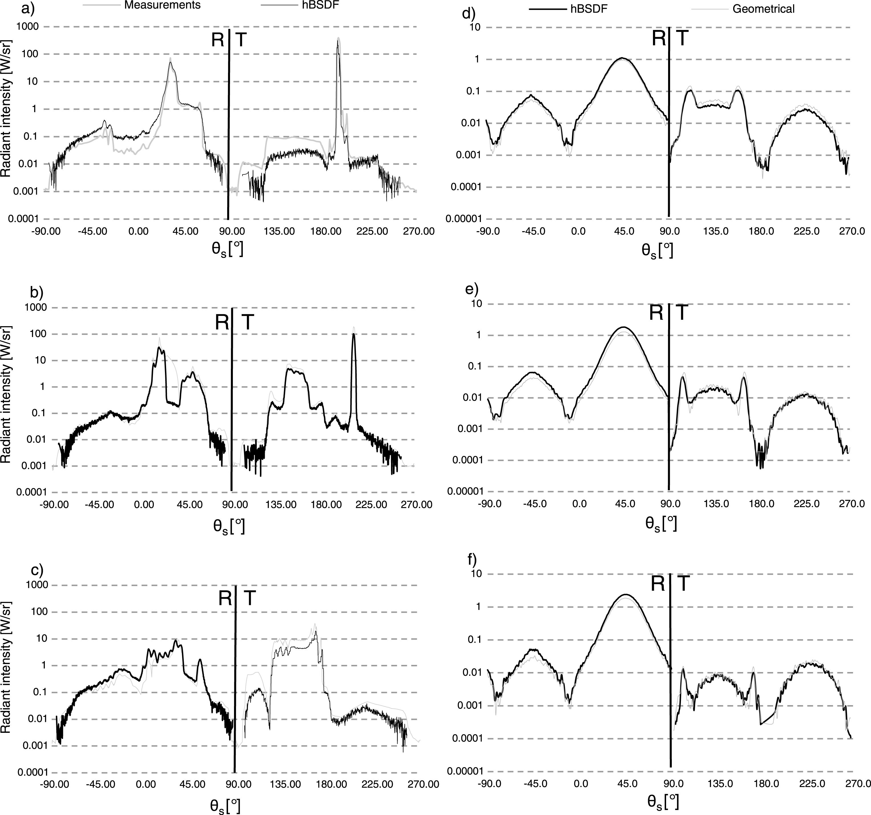
Similar to the comparisons presented in Fig. 6 the values for θs ranging from −90° to 90° represent the reflection data, while values from 90° to 270° represent the transmission data. On a vertical axis, radiant intensity [W/sr] is given on a logarithmic scale. In both types of comparisons (hBSDF vs measurements and hBSDF vs geometrical simulations) the compared profiles exhibited correlation to a very high degree. All profiles preserve the same number of peaks which are placed at the same position. Furthermore, the light scatter intensity is maintained throughout the whole profile. The only noticeable differences are the low-level signals in comparison between hBSDF and measurements. These differences vary from 0.01 to 0.1 [W/sr] and thus do not influence the simulation process significantly.
4Summary and conclusions
Within the course of this work we have proposed a method to generate hybrid BSDF models comprising both measured and simulated data. Such an approach allows the user to perform valid light simulation at close to grazing incident directions. Firstly, the comparison between geometrical simulations and data driven BSDF simulation was performed and revealed only minor miscorrelation. Consequently, the data obtained from geometrical simulations was utilized to compute BSDF values at grazing incident angles. These values were in turn applied to extrapolate and create the set of hBSDF values. The obtained hBSDF data set was compared to the formerly conducted geometrical simulations and exhibited a high degree correlation. Therefore, the proposed method can serve as a valuable tool for modelling the behaviour of DRCs and to perform more accurate modelling that features access to light incident directions close the grazing ones.
Notes
1 Images courtesy PAB Advanced Technologies Ltd, Freiburg.
Acknowledgments
This research was supported by the Swiss National Science Foundation as part of the project “Simulation-based assessment of daylight redirecting component for energy savings in office buildings” (#147053) and by CTI within the SCCER FEEB&D (KTI.2014.0119).
References
1 | Andersen M. , Rubin M. , Powles R. , & Scartezzini J. L. ((2005) ). Bi-directional transmission properties of venetian blinds: Experimental assessment compared to ray-tracing calculations. Solar Energy, 78: (2), 187–198. |
2 | Andersen M. , & Scartezzini J. L. ((2005) ). Inclusion of the specular component in the assessment of bidirectional distribution functions based on digital imaging. Solar Energy, 79: (2), 159–167. |
3 | Andersen M. , & de Boer J. ((2006) ). Goniophotometry and Assessment of bidirectional photometric properties of complex fenestration systems. Energy and Buildings, 38: (7), 836–848. |
4 | Apian-Bennewitz P. ((2010) ). New scanning gonio-photometer for extended BRTF measurements. Proc SPIE, 7792: , 77920O–1–20. |
5 | Ashikmin M. , Premože S. , & Shirley P. ((2000) ). A microfacet-based BRDF generator. Proceedings of the 27th annual conference on Computer graphics and interactive techniques, 65–74. |
6 | Bauer C. , & Wittkopf S. ((2016) ). Annual daylight simulations with evalDRC – assessing the performance of daylight redirection components. Journal of Facade Design and Engineering, 3: (3-4), 253–272. |
7 | Bonneel N. , van de Panne M. , Paris S. , & Heidrich W. ((2011) ). Displacement interpolation using lagrangian mass transport. ACM Transactions on Graphics (TOG), 30: (6), 158. |
8 | Claustres L. , Paulin M. , & Boucher Y. ((2003) ). BRDF measurement modelling using wavelets for efficient path tracing. Computer Graphics Forum, 22: (4), 701–716. |
9 | Cook R. L. , & Torrance K. E. ((1981) ). A reflectance model for computer graphics. ACM SIGGRAPH Computer Graphics, 15: (3), 307–316. |
10 | Geisler-Moroder D. , & Dür A. ((2010) ). A new ward brdf model with bounded albedo. Computer Graphics Forum, 29: (4), 1391–1398. |
11 | Grobe L. O. , Müllner K. , & Meyer B. ((2015) ). A novel data-driven BSDF model to assess the performance of a daylight redirecting ceiling panel at the calgary airport expansion. In PLDC 5th Global Lighting Design Convention, 240–243. |
12 | Grobe L. O. , Noback A. , Wittkopf S. , & Kazanasmaz Z. T. ((2015) ). Comparison of measured and computed BSDF of a daylight redirecting component. In CISBAT 2015 International Conference on Future Buildings and Districts, 205–210. |
13 | He X. D. , Torrance K. E. , Sillion F. X. , & Greenberg D. P. ((1991) ). A comprehensive physical model for light reflection. ACM SIGGRAPH Computer Graphics, 25: (4), 175–186. |
14 | Kautz J. , & McCool M. D. ((1999) ). Interactive rendering with arbitrary BRDFs using separable approximations. ACM SIGGRAPH 99 Conference abstracts and applications on - SIGGRAPH, 99: , 253. |
15 | Kazanasmaz T. , Grobe L. O. , Bauer C. , Krehel M. , & Wittkopf S. ((2016) ). Three approaches to optimize optical properties and size of a south-facing window for spatial daylight autonomy. Building and Environment, 102: , 243–256. |
16 | Krehel M. , Kaempf J. , & Wittkopf S. ((2015) ). Characterisation and modelling of advanced daylight redirection systems with different goniophotometers. Proc CISBAT 2015, International Conference. |
17 | Kurt M. , & Edwards D. ((2009) ). A survey of BRDF models for computer graphics. ACM SIGGRAPH Computer Graphics, 43: (2), 1. |
18 | Lafortune E. P. F. , Sing-Choong Foo Torrance K. E. , & Greenberg D. P. ((1997) ). Non-linear approximation of reflectance functions.’. Proceedings of the 24th annual conference on Computer graphics and interactive techniques - SIGGRAPH’97, 31: (3), 117–126. |
19 | Leloup F. B. , Forment S. , Dutré P. , Pointer M. R. , & Hanselaer P. ((2008) ). Design of an instrument for measuring the spectral bidirectional scatter distribution function. Applied Optics, 47: (29), 5454–5467. |
20 | Matusik W. , Pfister H. , Brand M. , & McMillan L. ((2003) ). A data-driven reflectance model. ACM Transactions on Graphics, 22: , 759. |
21 | Mohanty L. , Yang X. , & Wittkopf S. K. ((2012) ). Optical scatter measurement and analysis of innovative daylight scattering materials. Solar Energy, 86: (1), 505–519. |
22 | Montes R. , & Ureña C. ((2012) ). An Overview of BRDF Models. University of Grenada, Technical Report LSI-2012-001. |
23 | Ngan A. , Durand F. , & Matusik W. ((2005) ). Experimental analysis of BRDF models. In. Proceedings of the Eurographics Symposium on Rendering, 117–126. |
24 | Noback A. , Grobe L. , & Wittkopf S. ((2016) ). Accordance of light scattering from design and de-facto variants of a daylight redirecting component. Buildings, 6: (3), 30. |
25 | Phong B. ((1975) ). Illumination for computer generated pictures. Communications of the ACM, 18: (6), 311–317. |
26 | Reinhart C. F. , & Andersen M. ((2009) ). Development and validation of a model for a translucent panel. Information Systems Journal, 877: (2), 1–13. |
27 | Renhorn I. G. E. , & Boreman G. D. ((2008) ). Analytical fitting model for rough-surface BRDF. Opt Express, 16: (17), 12892–12898. |
28 | Schregle R. , Grobe L. O. , & Wittkopf S. ((2016) ). An out-of-core photon mapping approach to daylight coefficients. Journal of Building Performance Simulation, 1493: (May), 1–13. |
29 | Rusinkiewicz S. M. ((1998) ). A new change of variables for efficient BRDF representation. Rendering Techniques, 98: , 11–22. |
30 | Tian Z. , Weng D. , Hao J. , Zhang Y. , & Meng D. ((2013) ). A data driven BRDF model based on gaussian process regression. In Proc SPIE 9042, 2013 International Conference on Optical Instruments and Technology: Optical Systems and Modern Optoelectronic Instruments, Beijing. |
31 | Torrance K. E. , & Sparrow E. M. ((1967) ). Theory for off-specular reflection from roughened surfaces. Journal of the Optical Society of America, 57: (9), 1105. |
32 | Walter B. , Marschner S. R. , Li H. , & Torrance K. E. ((2007) ). Microfacet models for refraction through rough surfaces. Eurographics, 195–206. |
33 | Ward G. ((1992) ). Measuring and modeling anisotropic reflection. ACM SIGGRAPH Computer Graphics, 26: (2), 265–272. |
34 | Ward G. , Mistrick R. , Lee E. S. , McNeil A. , & Jonsson J. ((2011) ). Simulating the daylight performance of complex fenestration systems using bidirectional scattering distribution functions within radiance. In Leukos, 7: (4), 241–261. |
35 | Ward G. , Kurt M. , & Bonneel N. ((2015) ). Reducing anisotropic BSDF measurement to common practice reducing anisotropic BSDF measurement to common practice. Workshop on Material Appearance Modeling ((2014) ), Lyon, France. |
36 | Westin S. H. , Li H. , & Torrance K. E. ((2004) ). A comparison of four BRDF models. Proc Eurographics Symposium on Rendering, 1–10. |
37 | Yu Yeh-Wei , et al. ((2012) ). Bidirectional scattering distribution function by screen imaging synthesis. Optics Express, 20: (2), 1268–1280. |

