
Increased thermal induced climatic load in insulated glass units
Abstract
In the mid-1990s the climatic loading of double-glazed units (DGU’s) was investigated and design rules were developed for use in practice. Even though at the time those rules were developed for DGU’s, they have recently also been used for the design of modern triple-glazed units (TGU’s) and multilayer facade systems. So far, no research has addressed the question whether this design process, and in particular the temperature differences that have been determined for DGU’s, can be applied to other systems. It is therefore the aim of this paper to determine the governing temperatures in insulated glass units (IGU’s) under up-to-date boundary conditions. To do this, the thermal behaviour of TGU’s, multilayer facade systems and solar shading is investigated in detail. A simple calculation model is developed, which can be used to determine the gas temperatures in various facade configurations in accordance with the relevant standards. The results show that while parts of the existing requirements are still valid, there are distinct differences in the requirements for more contemporary applications. The gas temperatures affect the climatic load and therefore also influence the structural design of IGU’s.
Nomenclature
a | thermal diffusivity [m2/s] |
d | material thickness [mm] |
hi, he | internal and external heat transfer coefficients [W/m2K] |
hce | Convective heat transfer coefficient for external surfaces [W/m2K] |
hci | Convective heat transfer coefficient for internal surfaces [W/m2K] |
hs | convective and radiative surface heat transfer coefficient [W/m2K] |
n | amount of substance [mol] |
p | gas pressure [N/m2] |
p0 | isochoric pressure [kN/m2] |
heat flow density [W/m2] | |
rj | greaterthan thermal resistance of glass [mK/W] |
s | cavity width [m] |
C | specific heat capacity [J/kgK] |
Hh | cavity height [m] |
HTP | temperature penetration distance [m] |
Iα | radiation intensity at irradiation angle α [W/m2] |
Ij | radiative flux to the inside [–] |
I’j | radiative flux to the outside [–] |
R | general gas constant [J/(mol·K)] |
RSi, RSe | internal and external thermal resistance [m2K/W] |
R | thermal surface resistance [m2K/W] |
T | temperature [K] |
Tm | mean thermodynamic absolute temperature of the surface and environment [K] |
Text | absolute external air temperature [K] |
TS | absolute surface temperature [K] |
Tg | equivalent temperature in cavity [K] |
Tin | inlet temperature [K] |
Tout | outlet temperature [K] |
V | volume [m3] |
X | material property [–] |
Z | pressure drop factor [–] |
ΔH | elevation difference [m] |
Δpmet | air pressure difference [kN/m2] |
Δp0 | isochoric pressure difference [kN/m2] |
ΔT | temperature difference [K] |
α | radiative absorption [–] |
α | irradiation angle [°] |
γQ | safety factor [–] |
ɛ | surface emissivity [–] |
λ | thermal conductivity [W/mK] |
ρj | Radiative reflectivity from the outside |
ρ′j | Radiative reflectivity from the inside |
ρL20 | air density at 20°C [kg/m3] |
σ | Boltzman constant [W/m2K] |
ν | air speed [m/s] |
νh | rear ventilation air speed [m/s] |
τ | thermal time constant [s] |
τj | radiation transmissivity [–] |
ϑ | temperature [°C] |
μ | dynamic viscosity [Pas] |
Introduction
Modern construction is unimaginable without double- or triple-pane insulated glass windows. Triple-pane glass windows in particular are becoming more and more popular due to their excellent thermal insulation properties. Up to the late 1970’s double windows were used in most buildings in Germany (VFF/BF, 2014). They consisted of two separate glass panes with a cavity in between, which could be accessed for cleaning. Due to the oil crisis, the awareness of energy efficiency increased and new window types were developed. In the last forty years, single- and double-glazed windows gave way to a wide range of specialized high-performance insulated glass products.
1.1Climatic load for insulated glass
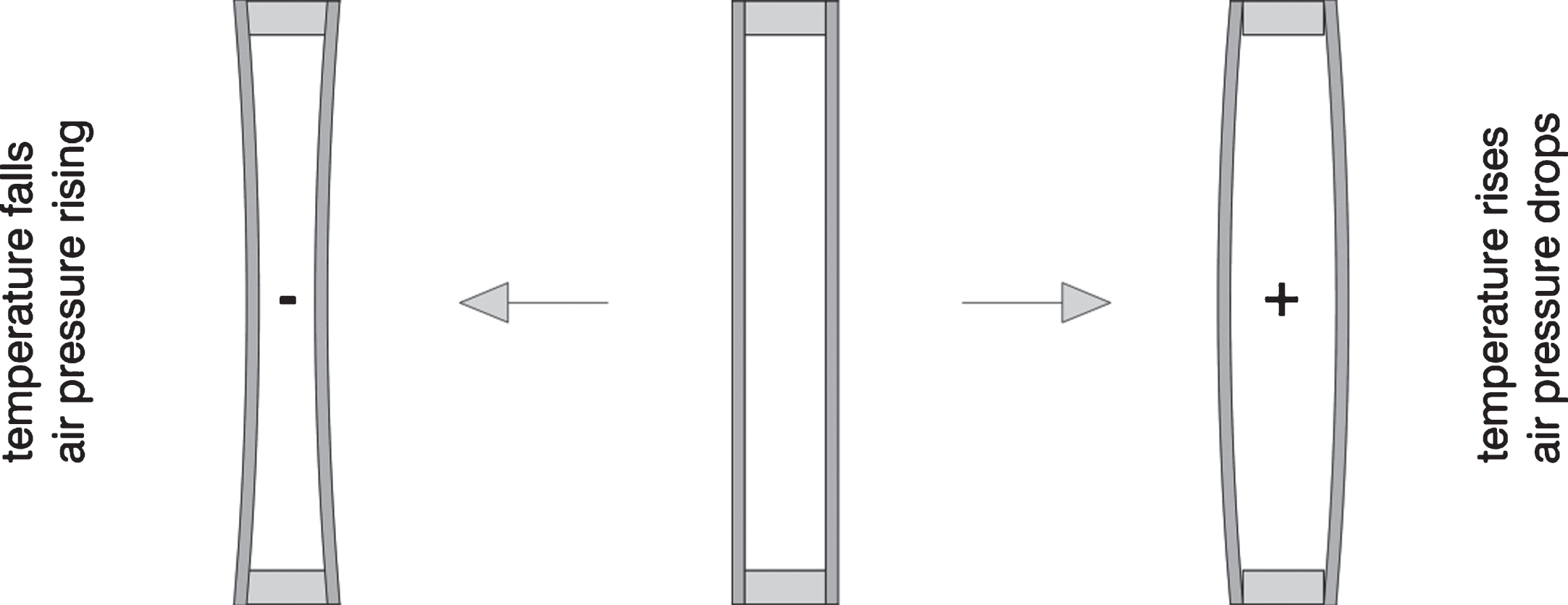
The climatic load is a specific internal load of insulated glass. The climatic load, also called insulated-glass effect, acts on the panes due to changes in the climatic conditions surrounding it. During the production of insulated glass units (IGU’s) each glazing cavity (GC) is sealed hermetically and the current state of the gas in production (volume, pressure, and temperature) defines the properties of the IGU. If the gas temperature or atmospheric pressure changes, a pressure difference between the GC and the environment occurs. The pressure balance can be restored by an increase of the volume in the GC, according to the ideal gas law (p×V = n×R×T = > (p×V)/(n×T) = constant. The expanding or contracting gas volume causes deformation (see Fig. 1), which in turn results in mechanical stress due to the climatic load.
Fig.1
Effect of climatic loads on Double Glazed Units.
This effect is known for quite some time and has been the topic of various research projects and publications. Practical approaches for the appropriate handling of this phenomena were developed by Feldmeier (1991), Feldmeier (1995) and Feldmeier (2000). The magnitude of the climatic load is expressed by the isochoric pressure p0. The isochoric pressure is defined as the pressure difference between the GC and the immediate environment that develops if the glass panes are rigid and cannot deform. It can be calculated by adding up three separate terms: the elevation difference ΔH, air pressure difference Δpmet, and temperature difference ΔT between the conditions at production and installation (Equation 1).
(1)
In Equation 1, the meteorological air pressure difference Δpmet (kN/m2) can be calculated directly from the meteorological air pressure difference, expressed in hPa (10 hPa = 1 kN/m2). The coefficient 0.012 in the term for the elevation difference is based on the linearization of the international barometric formula, which yields very accurate results for altitudes up to approximately 1000 m above sea level (Feldmeier (1995)). Amonton’s law (or Gay-Lussac’s second law) is used to calculate the isochoric pressure based on a change in temperature. This law stipulates that the pressure of ideal gases at a constant volume and a constant number of moles is directly proportional to the temperature. At normal pressure (1013.25 hPa) and an initial temperature of 25°C the factor for the change in isochoric thermal pressure is 0.34 kN/m2K.
1.2State of the art
Equation 1 for calculating the climatic load has been included in the Technische Richtlinie f ü r linienf ö rmig gelagerte Verglasungen TRLV (1998) since 1998 and in DIN 18008-2 : 2010 since 2010. Two load cases are considered: production in summer/installation in winter, and production in summer/installation in summer. To ensure a uniform design of insulating glass, the relevant standard parameters as well as the increase or reduction in temperature for non-standard situations are given in DIN 18008-1 : 2010 (see Table 1). Besides providing an approach for calculating the isochoric pressure p0, DIN 18008-1 : 2010 also contains an extensive number of formulae to determine the load distribution on double-glazed units (DGU’s), which take into account the coupling effect between the glass panes. The coupling effect describes the specific feature of IGU’s to transmit external loads from one pane to the next. The approach by Feldmeier (2006) is generally used to estimate the load distribution on triple-glazed units (TGU’s). Specialized software has been developed for this approach due to the complexity of the calculationsnecessary.
Table 1
Climatic load cases according to DIN 18008-1 : 2010
| Combination of actions | ΔT K | Δpmet kN/m2 | ΔH m |
| “Summer” | +20 | –2.0 | +600 |
| Part in Equation 1 | 0.34*ΔT = 6.8 kN/m2 | –Δpmet = 2 kN/m2 | 0.012*ΔH = 7.2 kN/m2 |
| “Winter” | –25 | +4.0 | –300 |
| Part in Equation 1 | 0.34*ΔT = –8.5 kN/m2 | –Δpmet = 4 kN/m2 | 0.012*ΔH = 3.6 kN/m2 |
The currently valid calculation values for ΔT were determined for double-glazed units with Ug = 1.8 W/m2K. Because of a lack of rules to the contrary, the values are currently also being used for the design of triple-glazed units with Ug<<1.0. Despite the rising popularity of TGU’s no studies exist with respect to the applicability of the DGU calculation values to TGU’s. Only Feldmeier (7/2009) mentions that the climatic load for triple-glazed units is slightly higher in summer. In practice, however, calculations using the standard cases according to the TRLV:2006, with p0 =±16 hPa, are still allowed. In specific cases these calculations need to be checked and reviewed thoroughly.
The European pre-standard prEN 16612 : 2013 provides analytical formulae to determine the temperatures in TGU’s that do not have any additional elements such as solar shading and glare protection. This standard, however, contains an example calculation for TGU’s which still uses the standard value p0 = –16 kPa as given in the TRLV 1998. The design provisions in the TRLV:2006/DIN 18008-1 : 2010 apply only to DGU’s with ventilated or non-ventilated internal glare protection, higher absorption classes, and thermal insulation behind the DGU.
According to Equation 1 and Table 1, temperature change constitutes a significant percentage (43% in summer 6.8/(6.8+2+7.2) and 53% in winter, 8.5/(8.5+4+3.6) of the climatic load for the standard cases in DIN 18008, which is why a more in-depth investigation is justified. The mean gas temperature in IGU’s has the largest impact on the climatic load and is also the parameter that is most influenced by its immediate environment. The temperature strongly depends on the selected IGU system (pane thicknesses and coatings) as well as the climatic and façade construction conditions. Hence, this is the focus of the present investigation. The standard values for calculating the climatic load have been adopted in German technical reference books and standards since 1998 (see for example TRLV (1998)). Even when the deterministic design approach from the TRLV was replaced with the semi-probabilistic design approach in DIN 18008-1 : 2010 (the same as in the Eurocodes), the values remained unchanged. For the latter approach, load safety factors needed to be considered at climate loads. Since the mean duration strength of float glass virtually remained the same, the load case “climate” became very important in the design of insulated glass.
Only two publications regarding the climatic load for IGU could be found in a literature survey. Two contributions by Penkova et al. (2013, 2014) deal with the thermal loading of IGU’s, with a particular focus on FE modelling of flat and bent DGU’s. The authors currently do not know of any general observations or estimates for gas temperatures of IGU’s in advanced facade types, for example for TGU’s and double-skin facades (DSF’s).
1.3Objectives
The present study deals with the climatic loads for IGU’s, focusing on the impact of different layer configurations in modern facade systems. The boundary conditions for IGU’s used in modern naturally, mechanically, or non-ventilated double-skin facades are not the same as the boundary conditions for IGU’s used in windows. Therefore, a detailed review of current standards will be conducted.
The objectives of this study are
–to analyse how DGU’s and TGU’s heat up under standard conditions in summer.
–to apply the gained knowledge to modern facade systems.
The behaviour of different systems will be illustrated, and suggestions will be made on how they can be dealt with in practice. A user-friendly and powerful calculation model is to be developed which will allow the determination of the temperature evolution in IGU facade systems under different climatic and construction conditions. The model is expected to illustrate all energetic processes in facade systems in accordance with the current standards. It is not required to yield results of the highest accuracy –a reasonably accurate representation of the processes under the given conditions, accurate enough for practical applications, are sufficient.
The results of the IGU-temperature study will be discussed in consideration of current design standards for IGU’s and those limitations. Suggestions for further improvements of structural IGU design will be made, if necessary.
2Method
2.1Model
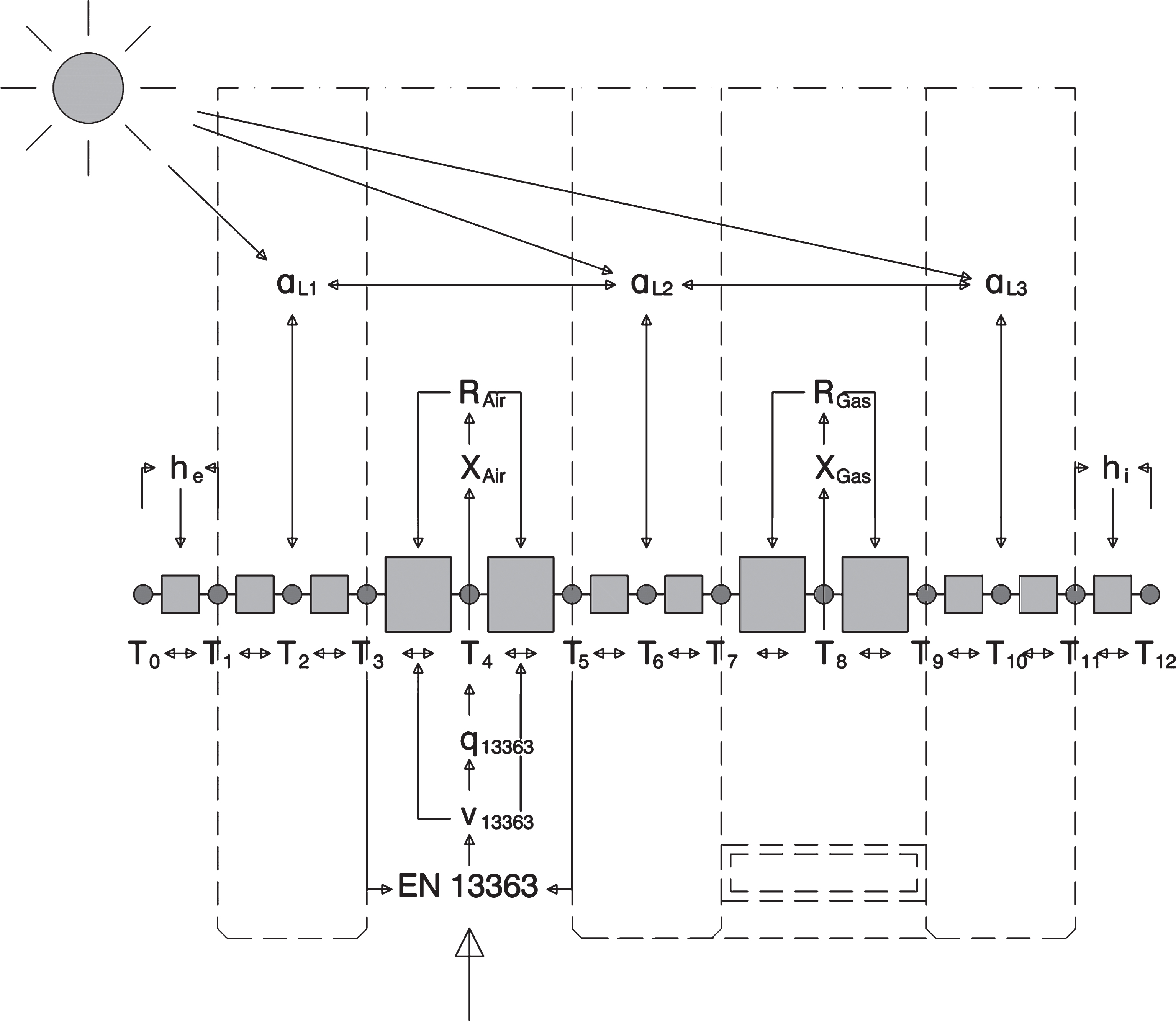
In this section, the physical basis and relevant provisions from the relevant standards required for the development of a calculation tool are presented. First, the physical principles of heat transfer are presented, as well as the calculation approach to determine the thermal resistances of gases and surfaces. Thermal as well as solar characteristics calculations are required to determine the solar energy flow in IGU’s. The implementation of a simplified optical model is also presented. Finally, the implementation of the iterative calculation tool is shown and illustrated with a flow chart. The following calculations refer to the overview flow chart shown in Fig. 3.
Fig.2
Schematic of multiple reflection in a facade with two transparent layers.
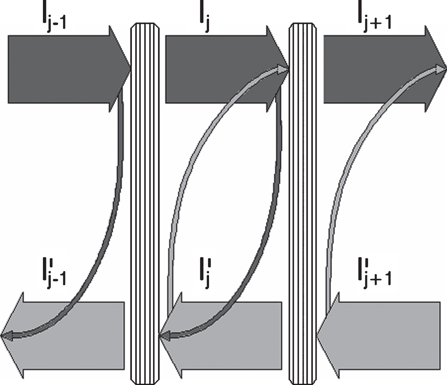
Fig.3
Schematic of nodes and iteration loops.
2.1.1Heat flow balance
The Fourier differential equation (Equation 2) combined with the law of conservation of energy is used for heat conduction calculations. For facade elements, it is sufficient to consider one-dimensional heat transfer in through-thickness direction. By eliminating the time dependency, the differential equation can be simplified further, and the expression in Equation 3 for the heat flow density
(2)
(3)
Because of the relatively small thermal time constant τ, it is justified to consider the thermal processes in IGU as stationary. The thermal time constant indicates how quickly a material reacts to changes in environmental temperature. According to Equation 4 with a = 53×10–8 m2/s for float glass, the thermal time constant is approximately 3 minutes for a 10 mm thick glass pane. The meteorological data available for simulations is generally collected in a one hour interval, a time period that far exceeds the thermal time constant of glass. Further, the temperature increase due to solar radiation does not only take place at the glass surface but also over the entire material cross-section. In practice, the temperature adjustment due to solar radiation will be less time consuming than described in Equation 4 from (Manz H., 2010):
(4)
The finite difference method is well suited for solving the thermal conduction equations numerically. To do this, the facade is discretized into a suitable number of nodes. Because of the linear nature of thermal conduction, it is not necessary to carry out a highly detailed discretization, which reduces the computational effort. The nodes are located at the internal and external boundary conditions, the mid-points of each layer, and at the interfaces between two layers, with the two layers sharing the interfacial area. The number of nodes N for n layers of material is given by Equation 5.
(5)
The sum of all heat flux
(6)
Therefore, the heat flows from node i to the neighbouring nodes i-1 and i+1 are:
(7)
It can be assumed that the incoming heat flows carry a positive sign and the outgoing heat flows carry a negative sign. Equation 7 can be extended to include external thermal flows by considering heat sources or heat sinks due to ventilation or solar gain:
(8)
(9)
The linear system of equations can be written as the following matrix (Equation 10):
(10)
Due to the direction dependence of the thermal conductivity the thermal resistances are:
(11)
The system of equations (Equation 10) can be solved numerically for any number of nodes N. The thermal resistances of the gas and air layers are dependent on their respective temperatures. The heat transfer coefficients and cooling efficiency of rear ventilations also refer to the system temperatures. Hence, the system of equations must be solved iteratively. Alternatively, the individual node temperatures can be included into the calculations by direct iteration. By rewriting Equation 9, an equation for the temperature of node Ti (see Fig. 3) is obtained, where all heat flows and thermal resistances in dependence of their neighbouring nodes Ti–1 and Ti + 1 are taken into account. Equation 12 can easily be solved iteratively.
(12)
2.1.2Thermal resistances of gases and surfaces
The thermal behaviour of the gases inside insulated glass is well known, and the approach for calculating the Ug-value under standard conditions is set out in EN 673 : 2011. If the temperature in the GC changes, the gas properties (XGas) also change, which in turn influences the thermal resistance of the GC (RGas) and the temperature calculations. This can be taken into account iteratively by using the temperature-dependent gas properties (XGas(T)) according to EN 13363-2, Appendix D, and Equation 13 in EN 673 : 2011 calculations. Compared to Fig. 3, this is used in Nodes T4 and T8.
(13)
The internal and external heat transfer coefficients of the glass surfaces are given in EN 673 : 2011. The contribution of the radiation to the surface heat transfer coefficients (hi, he), however, is determined according to EN ISO 6946 : 2007 (Equation 15 and 16, instead of EN 673) as the temperature-dependent radiation of a black body (Equation 14). EN ISO 6946 states that the external and internal radiation temperatures can be assumed to be approximately equal to the respective air temperatures.
(14)
(15)
(16)
2.1.3Optical model
In order to carry out calculations for different facade configurations, an optical model needs to be integrated into the calculation model. The solar and optical properties are independent of the intensity of the solar irradiation and the prevailing system temperature. The solar characteristics of IGU’s can be calculated according to EN 410 : 2011; those of IGU’s combined with solar protection devices can be determined according to EN 13363-2 : 2005. The equation system in Equation 17, developed by Stoll (2005) and visualized in Fig. 2, can be extended to any number of layers n. With the initial conditions I0 = 1 and I’n = 0 the system of equations can be solved to determine the layer absorptions αLi (see Fig. 3).
(17)
EN 13363-2 allows the use of integral values for the calculation if no spectral values are available, which is often the case for solar protection devices. In practice, often no differentiation is made between the luminous and solar characteristics. In this study, typical characteristic values for solar protection devices according to EN 13363-1, Appendix A, are used for a general examination of this issue. The values given are integrated values assuming that the difference between the properties of light and radiation are negligible.
To minimize the computational effort and the size of the included material library, it was investigated whether integrated characteristic radiation properties could also be used for glass layers. The integrated values for different glass layers were calculated with the web application glaCE (Glas Trösch AG, 2015) and included in the material library. A comparison of the results for different IGU configurations showed very small differences between the calculations with spectral values in glaCE and integrated values with this calculation model, as can be seen in Table 2. The results for the total absorption using the integrated values according to EN 13363-2, which was used in this publication, are marginally higher than those determined with glaCE, using spectral values. These higher absorption values also result in higher temperatures in IGU’s. Even with this small difference, however, the results are on the safe side and therefore acceptable. The differences in radiation transmission are somewhat higher, but they are of less importance for the present investigation.
Table 2
Comparison of spectral and integral radiation transmission and absorption
| Glazing | Calculation | Radiation transmission | Total absorption |
| DGU with low-e, pos. 3 | glaCE | 50.0% | 18.5% |
| Calculation model | 49.4% | 18.3% | |
| TGU with low-e, pos. 3&5 | glaCE | 37.2% | 26.5% |
| Calculation model | 31.0% | 27.7% |
2.1.4Natural ventilation model
In double-skin facades (DSF) with a connection to the external air, thermal pressure differences create an air flow called the stack effect (at node T4 in Fig. 3). Assuming that the air current is a uniform piston flow, air velocity, heat transfer, and heat loss can be calculated with the model given in EN 13363-2. The given formulae can be solved iteratively or as a system of equations (Equation 18).
(18)
The temperatures and cooling capacity are determined for the mid-section of the ventilated area and are given in Equation 19:
(19)
For a naturally ventilated double-skin facade extending over one story, the height of the ventilated space and the gap width for ventilation are assumed to be 3 m and 150 mm, respectively. These are very common values used in state of the art facade construction. The ventilation of interior glare protection can also be designed with this model. To model interior rear ventilation, a height of the ventilated space of 2.5 m and a ventilation gap width of 20 mm are used. In both cases, the lower and upper rear-venting openings are considered with 20 mm.
2.1.5Iterative implementation
As described in the previous sections, different calculation models are combined for this study and, due to the multifaceted temperature-dependent properties, calculated iteratively. Combining iterative calculations with explicit analytical formulae is a demanding challenge, which is why it was decided not to complicate the implementation further by using programming languages. A powerful implementation was achieved using Microsoft Excel with Visual Basic for Applications (VBA), with up to 32,767 iterative steps per calculation. A further advantage is the flexible and user-friendly user interface which makes it possible to include both pre- and post-processing within the same software environment.
Figure 3 shows how the elements of the Excel tool are related to each other, using the example of a simple facade – a naturally ventilated double-skin facade with a single glass pane on the outside and a DGU on the inside. The nodes are shown as temperature nodes (circles), and the thermal resistances are shown as squares. The arrows represent dependencies in the calculation, and double arrows signify an iterative calculation.
The required input data includes the facade layers, the internal air temperature as well as global radiation, and external air temperature. The facade configuration can range from a single glass pane with external solar protection or internal glare protection to open/closed double-skin facades with solar protection in the cavity, a TGU, and internal glare protection. The material thickness, thermal conductivity, optical properties, and surface emissivity of each solid layer are taken from the material library and used in the calculation. The properties of the gas layers are also taken from the material library or calculated from data in the library. The calculation steps are as follows:
1. Radiation absorptions αLi based on the solar characteristics of all layers.
2. Solar heat gain calculation in layers i.
3. Radiative transitions based on the emissivity of opposite surfaces.
4. Thermal conductivity of the gas layers.
5. Rear ventilation in the DSF cavity and resulting cooling performance in the DSF rear-ventilated space.
6. Rear ventilation between facade and inner solar protection and resulting cooling performance in the rear-ventilated space of interior blind.
7. Balance the temperature nodes, using the internal heat sources or heat sinks from step 2, 5 and 6 as well as the surrounding thermal resistivity values.
8. Repeat steps 3–8 until the convergence criterion of step changes <0.00001 is met.
2.1.6Accruals
2.1.6.1Emissivity
In the literature, for example in Frank (2010), the emissivity of a diverse range of materials and paints is generally assumed to be 0.95 (= 95%). The surface emissivity of uncoated glass is 0.837 (= 83.7%) according to EN 673 : 2011. The emissivity of glass coatings can be determined with standardized calculations given in EN 673 : 2011. Depending on the product, the resulting emissivity is 0.01–0.02 (= 1–2%). As worst case for overheating the lower value of 0.01 is used in the present contribution (see chapter 3.2.1).
2.1.6.2Fresnel
The angle of incidence of the radiation influences the transmission properties of glass panes. According to Fresnel’s law, the transmission decreases with increasing angle of incidence with respect to the surface normal.
The properties are almost constant up to an angle of approximately 45°. With increasing angle of incidence, the transmission decreases and the reflection increases. The absorption values, which are of major importance for this research, are constant up to 70°. Hence, it is not deemed necessary to implement Fresnel’s law.
2.2Facade studies
2.2.1Existing knowledge
The goal of this investigation is to increase the existing amount of temperature data of gases in IGU’s and to optimize the calculation of the climatic load. To do this, the basis of the calculation for the temperature values according to DIN 18008-1 : 2010 has to be taken into account. The requirements of the TRLV:2006/DIN 18008-1 : 2010 are to form the basis for assessing the influence of different IGU’s in different facade configurations. The winter conditions do not include solar radiation, and the stipulated external and internal air temperatures are ϑe = –10°C and ϑi = 19°C, respectively. The external and internal heat transfer resistances are RSe = 0.04 m2K/W and RSi = 0.13 m2K/W, and the U-value of the DGU is supposed to be 1.8 W/m2K.
The summer conditions are based on an irradiation of 800 W/m2 at an angle of incidence of 45° and with an absorptivity that is 30% for a DGU. External and internal air temperatures of ϑe =ϑi = 28°C are used. The heat transfer resistances are set at RSe = RSi = 0.12 m2K/W. The applicability of these conditions is discussed later in this paper.
2.2.2Extensions of the system
Even though the TRLV assumes single-skin facades (SSFs) with DGU’s, this assumption no longer represents the use of IGU’s in modern facade construction. Over the last years there has been a tendency to use TGU’s in facades. When determining the climatic load, TGU’s are often likened to DGU’s: “Removing the middle glass pane, one ends up with double glazing!” (Feldmeier, 7/2009, quote translated from German). This simplification is valid for loading of the external panes under identical isochoric pressure. Whether it also applies to TGU’s will be investigated in this study.
Many modern office buildings have large glass facades, sometimes double-skin facades. Double-skin facades consist, simply put, of a facade with an additional glass skin in front of it. The external solar protection elements are located in the cavity between the external and the internal glass panes, which affords them with significantly improved wind and weather protection. Double-skin facades are generally ventilated naturally, so that an air current develops between the two facades due to the natural, thermal driven air currents. Various investigations and publications have dealt with the thermal behaviour of DSF’s. Balocco (2002) and Manz and Frank (2005), for example, both state that buildings with DSF’s show a significant tendency to overheat in summer. According to Pasquay (2003), the temperatures in the cavity rise to 10–15 K above the ambient temperature even in well-ventilated DSF’s. Therefore, the energy loss from the IGU to the outside is hampered severely, and heat flows towards the interior of the building.
The closed DSF, called closed-cavity facade (CCF’s), is a relatively new facade type. One of the first CCF’s was built in 2009 by Josef Gartner GmbH at Roche headquarters in Rotkreuz, Switzerland (Burkhard + Partner AG, 2015). In this type of DSF the cavity between the interior and exterior skins is completely closed. A small current of air-conditioned air is fed into the cavity, which prevents the entry of humidity and dirt. Because of the missing strong air current, the cavity can heat up even more, in particular when the solar shading louvers are closed.
The objective of this study is to extend the thermal investigations to DGU’s and TGU’s in different types of vertical facades. To do this, the different combinations of layers are subsumed in a combination matrix; cf. Figure 4. All the combinations of internal and external constructional boundary conditions are represented. The internal constructional boundary conditions are shown in the first column (vertical); the external constructional boundary conditions are shown in the first row (horizontal).
Fig.4
Investigated facade configurations containing double- and triple-glazed units.
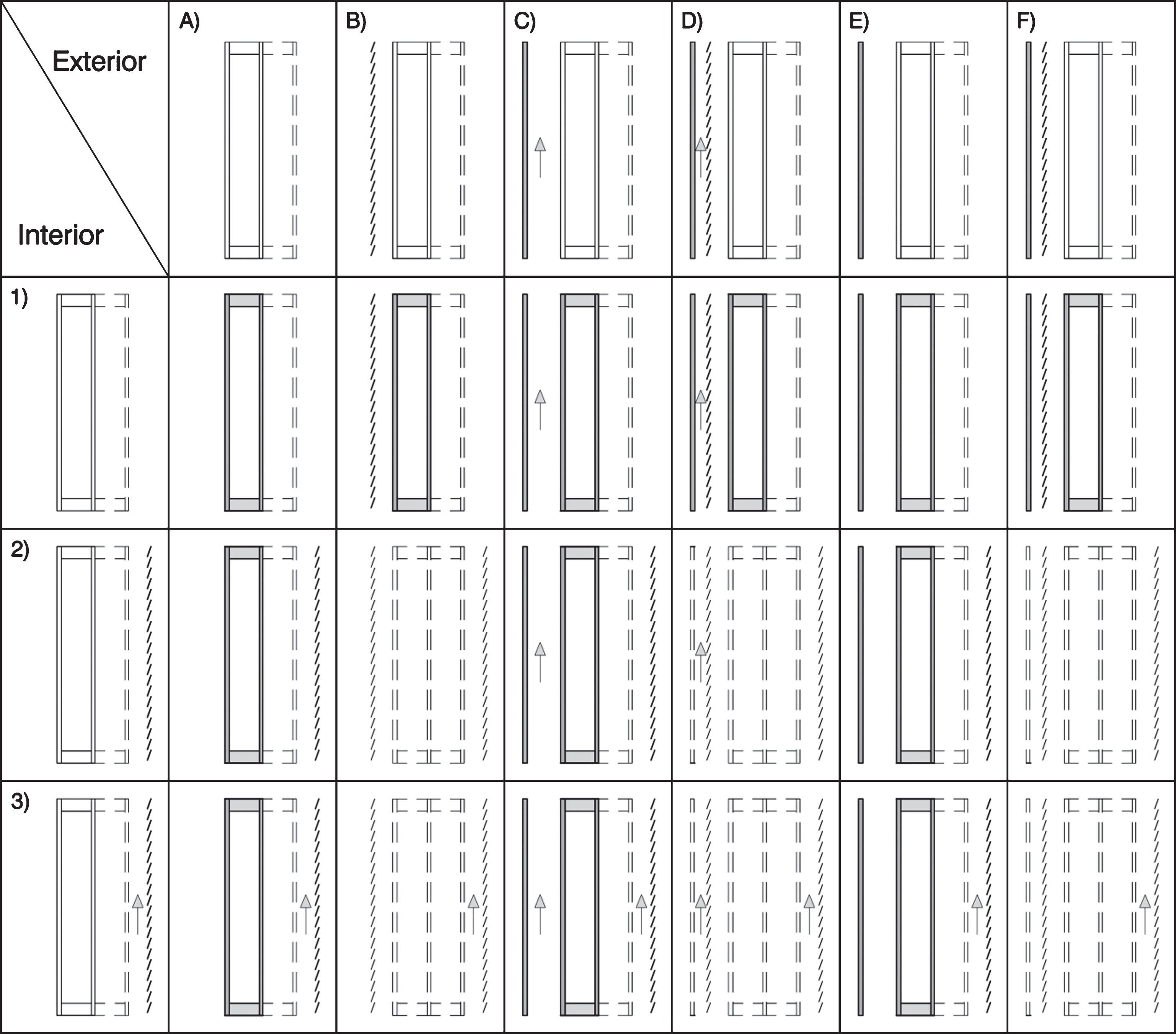
Internal constructional boundary conditions, from top to bottom: 1) none; 2) ventilated glare protection; 3) non-ventilated glare protection. External constructional boundary conditions, from left to right: A) none; B) external solar protection; C) ventilated DSF without solar protection; D) ventilated DSF with solar protection; E) CCF’s without solar protection; F) CCF’s with solar protection.
The combinations of transparent external solar protection and internal solar protection devices have not been considered.
2.2.3Approach
In a first step, the standard conditions according to DIN 18008-1 : 2010 are employed in chapter 3.1. They serve as reference conditions against which the impact of changes to the systems can be assessed. Furthermore, the properties of insulated glass are updated to reflect the state of the art. Chapter 3.2.1 describes the extension of the calculations to TGU’s. In 3.2.2 DGU’s and TGU’s of different thicknesses are investigated. The influence of the glass thickness and absorption are then compared with the stipulations from DIN 18008-1 : 2010.
In chapter 3.3 the impact of changes to the constructional boundary conditions according to Fig. 4 is investigated. Initially, single-skin facades with internal and external solar protection devices are examined, followed by double-skin facades. Investigations are carried out for the different facades containing DGU’s or TGU’s. Comparing the results with those from the single-skin calculations obtained in step 1, it can be seen if there is a significant increase in temperature.
3Results
3.1Comparison of current glazing with stipulations from relevant standards
First, the gas temperatures for IGU’s stipulated in DIN 18008-1 : 2010 are considered. To verify the suggested approach and allow a comparison with current boundary conditions, a detailed analysis of the boundary conditions from the standard is carried out. Following this, the boundary conditions are modelled with the calculation program. By incrementally altering the standard boundary conditions to the actual boundary conditions, the influence parameters are determined.
It is possible to model the “standard situations” according to the TRLV/DIN 18008-1 : 2010, Section 2.2.1. While a lot of information is available, the emissivity of the coating inside the glazing cavity is not known. It is permitted to choose the emissivity value so that the U-values for both summer and winter load case are 1.8 W/m2K. When also considering the temperature-dependent gas properties, the required emissivity of the coating in summer is determined to be approximately ɛ= 0.2. The stipulated limit of 30% absorption for summer is exceeded slightly when 2×10 mm float glass is used (32.4%). It is not even possible to reach an absorption value of >50% in a DGU consisting of 2×19 mm float glass (radiation absorption according to glaCE 44.8%).
The TRLV prescribes a mean gas temperature at the construction site of 2°C in winter; the calculation with the presented model yields the same result (2.2°C). In a modern DGU with a low-e (low-emissivity) coating (ɛ= 0.01) a temperature of 3°C is reached, which deviates less than 1 K from the stipulated value in the standard situation. The situation is somewhat different for summer conditions, which include the impact from radiation. The radiation intensity of 800 W/m2 and the irradiation angle must be converted in order to be used in the energy balance. The intensity of the solar radiation on an inclined surface can be calculated with a simplified approach, using the cosine of the irradiation angle (Equation 20). This irradiation is used for all cases; the influence of the angle-of-incidence is negligible (see section 2.1.6.2).
(20)
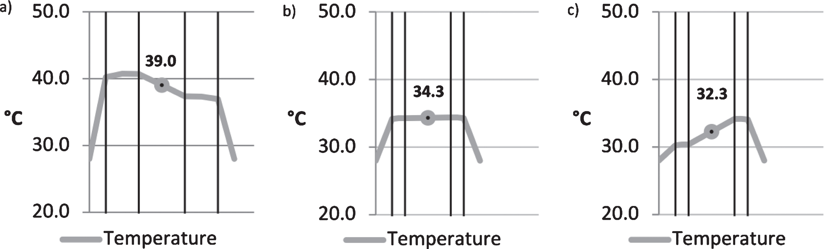
The external and internal heat transfer resistances are given as Re = Ri = 0.12 m2K/W in the TRLV, resulting in a mean gas temperature of 39°C (see Fig. 5a). This result can be confirmed by a quick calculation by hand using Equations 21–23:
Fig.5
Comparison of glazing according to the TRLV under summer conditions with a) 2×10 mm, b) 2×4 mm and c) 2×4 mm with he/hi according to EN 673 : 2011.
(21)
(22)
(23)
In modern DGU’s with low-e coatings (ɛ= 0.01) 10 mm float glass is rarely used. It is more common to use 2×4 mm float glass, for which the total absorption is approximately 18.3%. Therefore, the temperature in the glass cavity drops to 34.3°C; see also Fig. 5b. The difference to the ambient temperature hence decreases from 11 K to 6.3 K. Using the internal and external heat transfer resistances according to EN 6946 (approximately RSe = 0.04 m2K/W and RSi = 0.13 m2K/W according to EN 673 : 2011) the temperature decreases even further, to 32.3°C (see Fig. 5c). This value is approximately 7 K lower than the stipulations found in the TRLV:2006/DIN 18008-1 : 2010. For the climatic load in summer according to Equation 1, a temperature difference ΔT of +20 K is used (39°C –19°C). Using the presented calculation, however, this difference is reduced to 13 K (32°C –19°C). As a consequence, the isochoric pressure resulting from the change in temperature decreases by an impressive 35%, and the total climatic load for summer drops by 15%.
3.2Extension of the calculations to TGU’s
The IGU system changes due to the addition of another glass pane and gas cavity. According to a publication by Feldmeier (2011), it is well known that the climatic loads are higher for TGU’s due to their larger gas volumes. In this section, it is investigated how the additional glass cavity and middle glass pane change the thermal behaviour of TGU’s compared to DGU’s.
3.2.1Behaviour of simple TGU’s
For all further calculations, the thermal transfer resistances are calculated according to Section 2.1.3, using 4 mm float glass. The gas cavities are assumed to be 14 mm and filled with 90% argon. A low-e coating with ɛ= 0.01 is assumed in position 3 in DGU’s and in positions 2 and 5 in TGU’s. A TGU with 3×4 mm float glass has a total radiation absorption of 29.3%, which is just below the 30% threshold.
Because of the two gas cavities, TGU’s exhibit a temperature gradient with two different mean gas temperatures in winter. While the mean gas temperature in a DGU is 2.9°C, the mean temperatures in a TGU are –2.6°C and 10.4°C. The winter load case according to the TRLV stipulates a temperature of 27°C at production and 2°C at installation. Instead of this temperature decrease of –25 K, two temperature drops of –29.5 K and –16.5 K are considered for a TGU. This results in an isochoric pressure difference of Δp0 = 4.4 hPa between the two gas cavities.
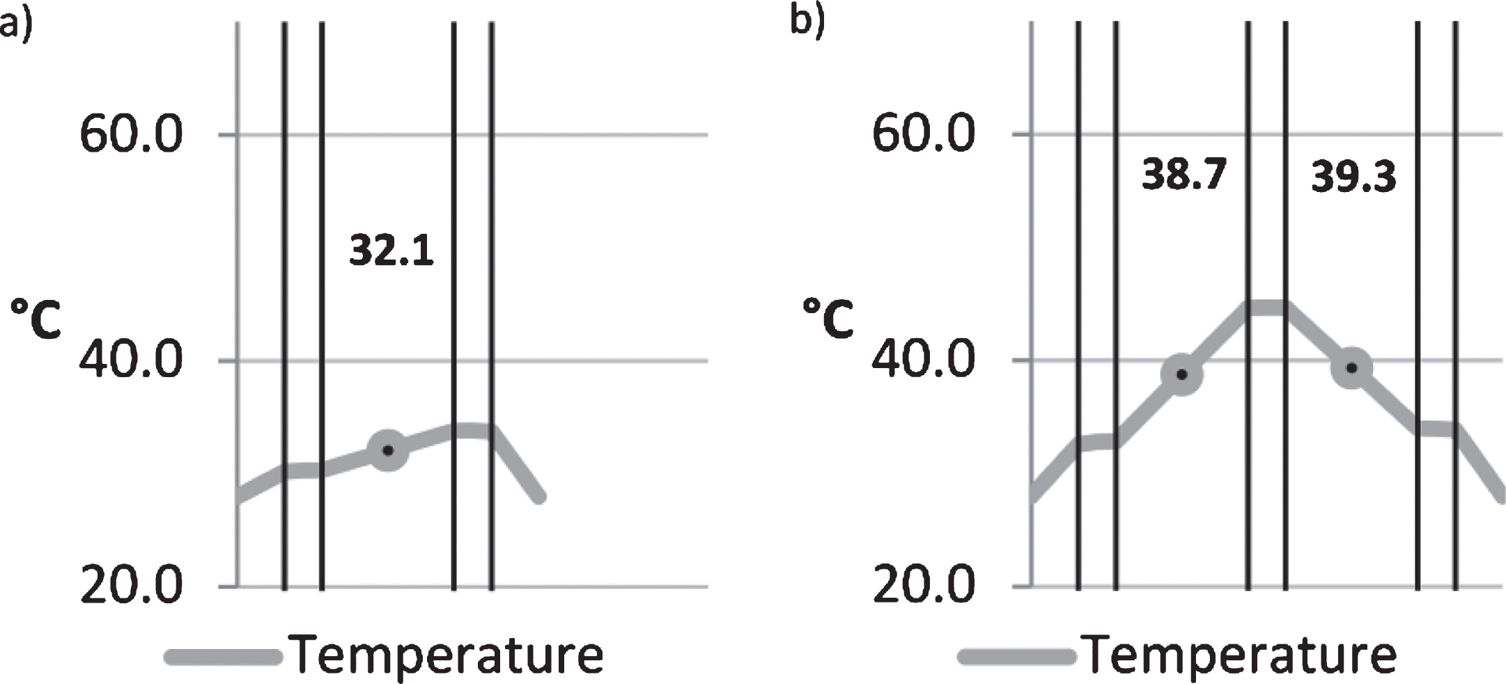
TGU’s also react differently under summer boundary conditions than DGU’s. As can be seen in Fig. 6, the additional middle pane also absorbs solar energy and heats up. Further, the two gas cavities and low-e coatings make it more difficult for the middle pane to release energy, which must be compensated with a greater ΔT according to Fourier’s equation for thermal conduction (Equation 3). Therefore, the middle pane experiences a significantly higher temperature increase than the external panes, which leads to the higher mean gas temperatures in TGU’s compared to DGU’s.
Fig.6
Comparison of modern double- and triple-glazing units under TRLV:2006 summer conditions, with he/hi according to EN 673 : 2011.
3.2.2Influence of the glass thickness
The influence of the glass thickness on the temperatures in IGU’s is clearly illustrated in Fig. 5 for different configurations of DGU’s. The glass thickness and the resulting absorption determine the temperature increase according to physical laws. The behaviour of DGU’s and TGU’s with glass panes of different thicknesses has not been investigated so far. For winter conditions, such an investigation is not necessary, as the thermal resistance of glass (rj = 1.0 mK/W according to EN 673 : 2011) only adds a minimal contribution to the total thermal resistance of IGU’s.
To illustrate the influence of the glass thickness, a comparison of differently configured DGU’s and TGU’s under summer conditions is carried out with the presented calculation program. The DGU’s are compared with a symmetrical configuration consisting of X mm float glass/GC/X mm float glass. For TGU’s two different configurations are used:
- Thicker exterior glass pane: X mm float glass/GC/4 mm float glass/GC/X mm float glass
- Thicker middle glass pane: 4 mm float glass/GC/X mm float glass/GC/4 mm float glass
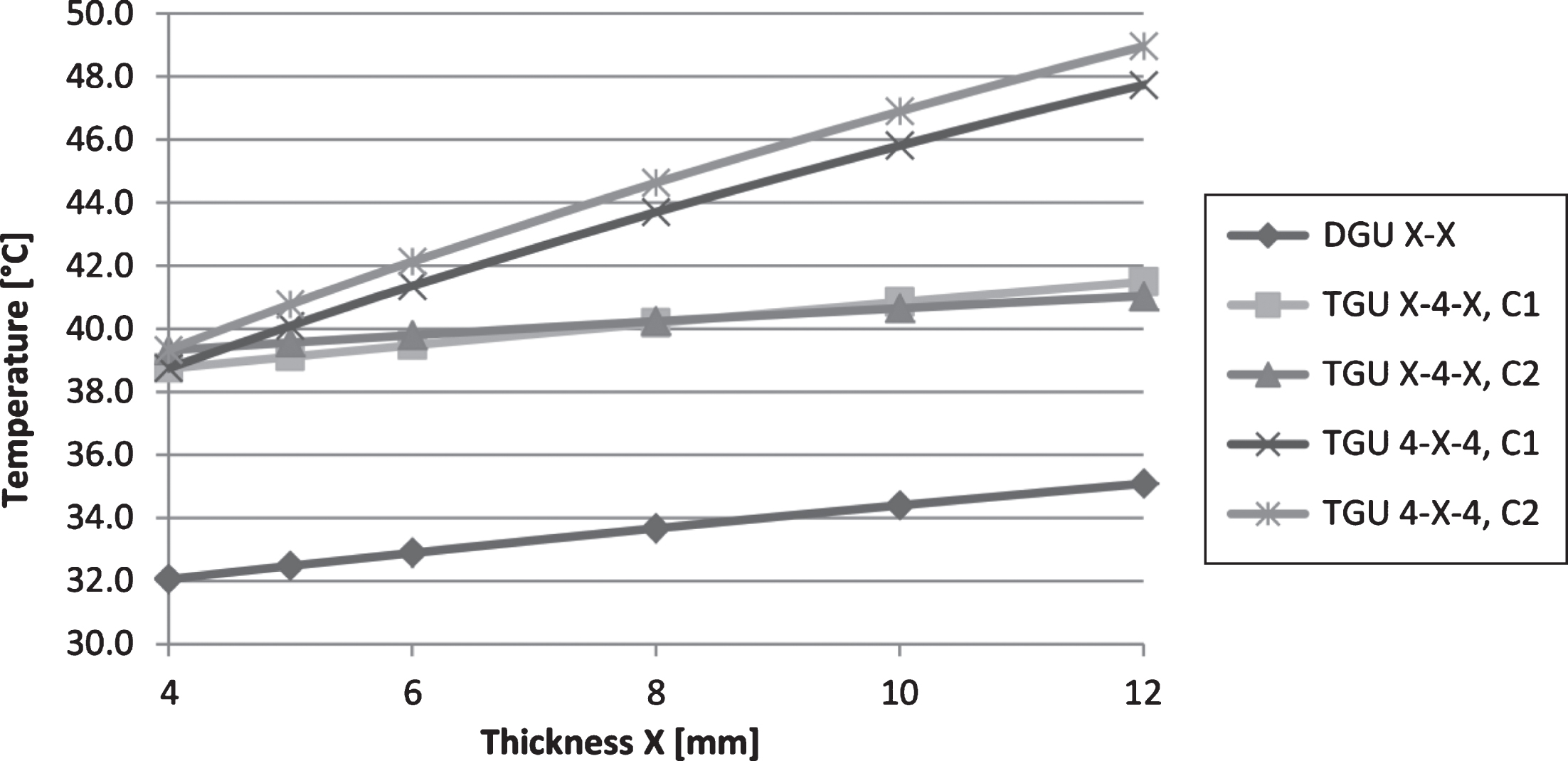
Figure 7 shows that under identical conditions the temperatures of TGU’s are significantly higher than those of DGU’s. The curves are approximately linear. The results become even clearer if the linear slope coefficient of a linear equation of the form y = m * a + b is considered. The mean slope m of the temperature curve for the DGU is 0.36 K/mm, and that of the curve for the TGU with the thicker exterior glass panes is 0.27 K/mm. This shows that thicker exterior panes have a smaller influence on the temperatures of a TGU with respect to a DGU. In contrast, the middle pane has an extremely strong influence on the temperature of the TGU; the slope of 1.06 K/mm is more than three times greater than that of the other configurations.
Fig.7
Comparison of temperatures in the glass cavity of DGU’s and TGU’s.
3.3Influence of layer configuration
Just as temperature gradients are related to the characteristics of DGU and TGU systems, modifications in the facade system itself also lead to differences in temperature distributions. This section deals with the impact of internal and external solar protection devices. An investigation of the temperatures in modern double-skin facades with and without internal solar protection follows. Both DGU’s and TGU’s and their temperatures are examined with respect to IGU’s without solar protection.
3.3.1Solar and glare protection devices
The influence of internal solar protection devices is considered in the TRLV. The temperature to be added to ΔT for summer conditions is 9 K for ventilated solar protections (= 48°C in the gas cavity) and 18 K for non-ventilated solar protection (= 57°C in the gas cavity). The comparative calculations show that these values can indeed be reached with opaque, black internal solar protection (based on the TRLV summer scenario including the boundary conditions). The investigations using the presented calculation program show that the results are strongly dependent on the chosen transmission and colour properties of the solar protection. With increasing solar absorbance, a temperature increase can be observed in DGU’s. Without solar protection, temperatures of 32°C are reached. However, if solar protection is considered, temperatures of 37–42°C and 40–46°C can be reached in systems with ventilated and unventilated interior solar protection devices, depending on the colouring. The temperature increase is hence significantly smaller than that stipulated in the TRLV because of the distinctly higher energy transfer to the outside, which is due to the heat transfer coefficient for external surfaces he given in EN 673 : 2011.
There are no stipulations for exterior solar protection devices in the TRLV. Depending on the facade configuration, however, they can also cause a temperature increase in DGU’s. Depending on the colour intensity of the solar protection, the temperatures can be 0–5 K higher in single-skin facades than the 32°C shown in Figs. 5 and 6. As exterior solar protection devices are more often opaque than not, a temperature no higher than 37°C should be used in the calculation, even for glass with higher absorption. Because this temperature is lower than the original 39°C stipulated in the TRLV, no relevant rules can be found in this guideline. The influence of exterior solar protection devices in double-skin facades is discussed later in this article.
The thermal behaviour of TGU’s with interior solar protection devices is somewhat different than that of DGU’s. The presence of internal solar protection leads to higher gas temperatures, with lighter-coloured materials inducing higher temperatures. The reflection of the solar protection increases with lighter colours, thereby increasing the absorption of the middle pane, which is already subjected to higher thermal loads. Depending on the colouring of the solar protection, the mean gas temperatures increase from approximately 39°C (cf. Fig. 6b) to 44–51°C and 45–56°C (cf. Fig. 8a) in systems with ventilated and non-ventilated interior solar protection devices, respectively. The inner gas cavity heats up slightly more than the outer one, which leads to asymmetric climatic loading of the two gas cavities.
Fig.8
TGU with (a) interior and (b) exterior black, opaque solar protection.
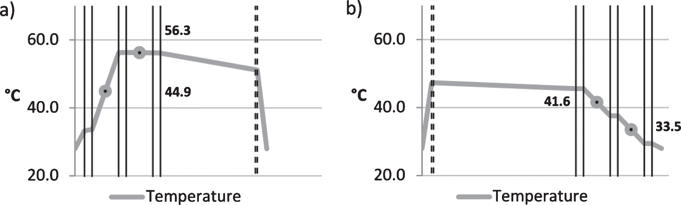
The calculations for a TGU with external solar protection yield different results. In the case of opaque protection, except for black opaque elements according to Fig. 8b, the gas temperatures are lower than the reference temperatures of 38.7°C/39.3°C of the uninfluenced TGU according to Fig. 6b. In systems with elements of medium and high transparency, the temperature in the outer glass cavity increases by 1–7 K, while the temperatures in the inner glass cavity remain below 39°C. A distinct temperature gradient is present in the facade, where the lowest temperatures are found towards the interior of the building. Figure 8 shows the temperatures under summer conditions in a TGU with exterior and interior solar protection devices.
3.3.2Double-skin facades (DSF)
When calculating the U-value of glazing in a DSF it is common practice to set the heat transfer coefficient for the external IGU surfaces equal to that for the internal surfaces (he = hi = 0.13 m2K/W). This approach also yields good approximate values for layer temperatures without any other influences like shading devices. Temperatures of 34.6°C and 46.2°C/42.3°C are determined for the DGU and TGU, respectively. The exact calculations with the model of natural rear ventilation according to EN 13363-2 yield temperatures of 35.7°C and 46.7°C/41.3°C for the DGU and the TGU, respectively. The results differ merely by 1.1 K (DGU) and <1 K (TGU). This simplification, however, is only applicable to the simplest case of a DSF.
If solar protection in the DSF is taken into account as well, the system changes significantly and the simplified approach no longer applies. The following calculations are based on external glazing consisting of 8 mm float glass, a cavity of 150 mm, and internally installed solar protection. When the solar shading louvers are closed, only the outer cavity is ventilated, and the air volume between solar protection and IGU is considered unventilated, containing a resting air layer (see also Fig. 4).
The calculated mean gas temperatures of the DGU inside the DSF range from 35.7°C (no solar protection) to 38.1°C (white solar protection) and 50.7°C (black, opaque solar protection). If the DGU is replaced by a TGU, the temperatures increase to 46.7°C/41.3°C (no solar protection) and 61.9°C/41.9°C (black, opaque solar protection). These temperatures are considerably higher than those of a single-skin facade according to Fig. 6b. The temperatures for systems with differently coloured solar protection according to EN 13363 are summarized in Table 3.
Table 3
Mean gas temperatures in the IGU of a naturally ventilated facade, including exterior solar protection devices
| Solar protection | Gas temperature in DGU | Gas temperature 1 in TGU | Gas temperature 2 in TGU |
| none | 35.7°C | 46.7°C | 41.3°C |
| White colour | 38.1°C | 43.3°C | 34.2°C |
| Pastel colour | 42.7°C | 50.1°C | 37.0°C |
| Dark colour | 46.8°C | 56.2°C | 39.6°C |
| Black colour | 50.7°C | 61.9°C | 41.9°C |
3.3.3Closed-Cavity Facades (CCF’s)
In a closed-cavity facade the cavity is not ventilated. The mechanical aeration is very small and is thus not capable of cooling the facade cavity. Therefore, higher temperatures are to be expected in this closed system. The air volumes between the exterior and interior glazing are considered as layers of resting air.
Even without solar protection devices in the cavity, the gas temperatures are marginally higher than those in a ventilated DSF –36.7°C in the DGU (+1 K) and 49.6°C/42.4°C (+3.1 K/+1.1 K) in the TGU. The temperature increase is significantly higher if the louvers of the solar protection are closed. For the extreme case of black, opaque sun protection in the CCF’s the temperatures in the DGU and TGU are 56.5°C and 71.1°C, respectively. Further results can be found in Table 4.
Table 4
Mean gas temperatures in the IGU of a CCF’s with exterior solar protection devices
| Solar protection | Gas temperature in DGU | Gas temperature 1 in TGU | Gas temperature 2 in TGU |
| none | 36.7°C | 49.6°C | 42.4°C |
| White colour | 40.6°C | 47.2°C | 35.8°C |
| Pastel colour | 46.3°C | 55.9°C | 39.5°C |
| Dark colour | 51.6°C | 63.8°C | 42.8°C |
| Black colour | 56.5°C | 71.1°C | 45.8°C |
3.4Summary of the results
This section presents a summary of all calculated temperatures. Next to showing the temperatures for the previously analysed cases, Figs. 9 and 10 also contain results for further cases, such as external and internal, partly transparent, and differently coloured solar protection devices.
Fig.9
Calculation results overview for DGU’s in different facade systems.
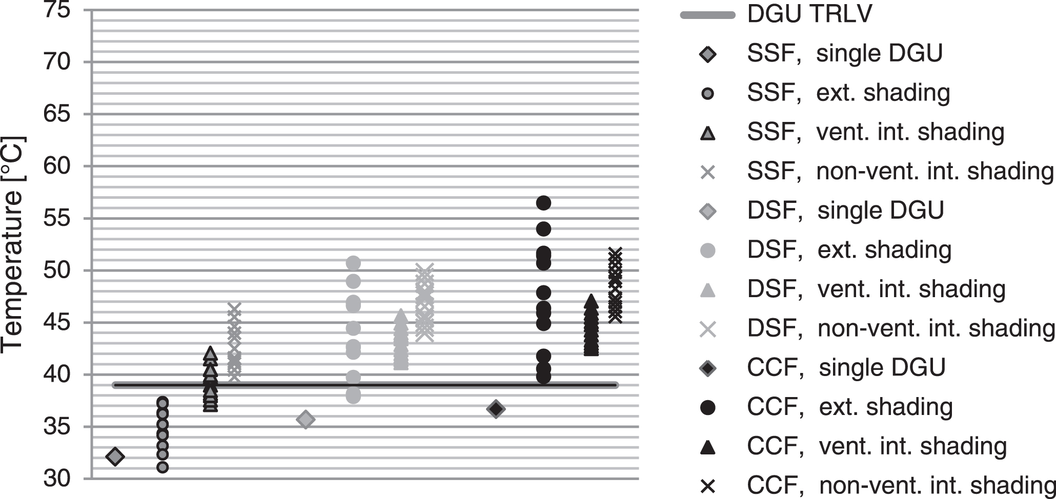
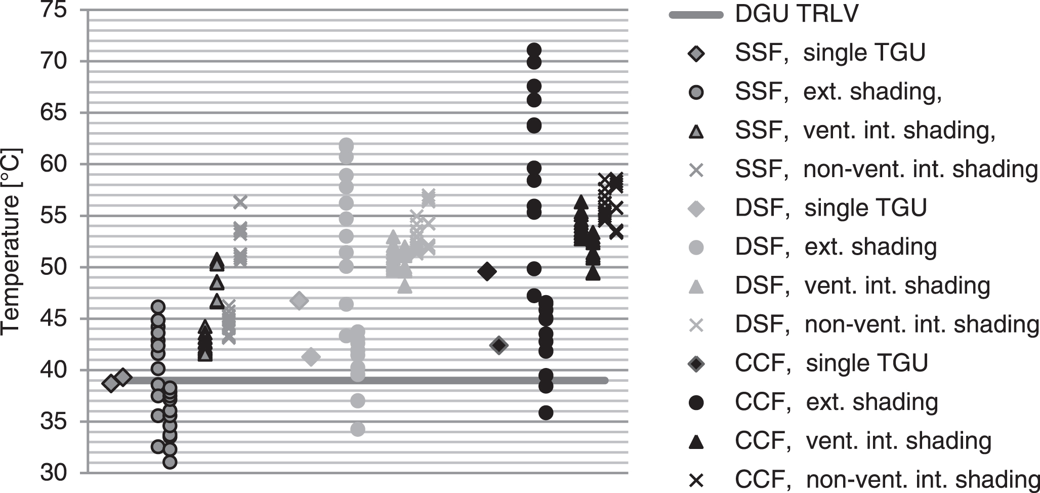
Fig.10
Calculation results overview for TGU’s in different facade systems.
3.4.1Double-glazed units
The mean gas temperatures in a DGU consisting of the commonly used 2×4 mm float glass panes are significantly lower than those stipulated in DIN 18008-1 : 2010. This includes taking into account the heat transfer resistances according to EN 6946/637 : 2011. The presented calculations also show that the influence of ventilated and non-ventilated interior shading elements is smaller than that estimated from DIN 18008-1 : 2010.
The differences are most pronounced, however, for facade systems that have not been included in the TRLV:2006/DIN 18008-1 : 2010. If exterior solar protection is installed on a single-skin facade, significantly higher temperatures can be reached than in an individual DGU. Those temperatures, however, are still below the current design temperature of 39°C. It is shown that the temperatures are lowest in the single-skin facade and higher in the double-skin facade, and that the highest temperatures occur in the closed-cavity facade. DGU’s with thin glass panes in double-skin facades without solar protection devices are not relevant for climatic load design. For DSF’s and CCF’s, the presence of exterior solar protection can be relevant for the design, and the temperatures can be even higher than those for the case of interior solar protection. The results for DGU’s consisting of 2×4 mm float glass panes are shown in Fig. 9.
3.4.2Triple-glazed units
The TRLV:2006/DIN 18008-1 : 2010 do not deal with the mean gas temperatures in TGU’s. The results of the presented calculations show that, under DIN 18008-1 : 2010 boundary conditions, the temperatures in a TGU consisting of 3×4 mm float glass (<30% total absorption) are the same or higher than those stipulated in the current TRLV (39°C for <30% absorption). Although the effect of exterior solar protection devices is insignificant in single-skin facades, it is considerably relevant for DSF’s and CCF’s.
The results for TGU’s used in different facade configurations are shown in Fig. 10. The same markers are used for both gas cavities – the outer cavities are shown on the left-hand side, the inner cavities on the right-hand side. For a distinct overview, associated pairs are not shown here. It can clearly be seen that only 22 of the 222 calculated temperatures in the 111 different facade systems are below 39°C, mainly those of systems with exterior solar protection. Generally, the temperatures in TGU’s are significantly higher than those in DGU’s (see Fig. 9). This agrees with the previous results, which indicate that multilayer facades tend to exhibit considerably higher temperatures.
4Discussion
4.1Facade configurations
In the present study, many facade configurations were examined which are either not considered, or explicitly excluded from consideration in DIN 18008-1 : 2010 (see Fig. 4). The TRLV:2006 and DIN 18008-1 : 2010 do not provide values for TGU’s; however, in 18008-2 : 2010 the reader is referred to Feldmeier (2006) for information on the load distribution for TGU’s. As TGU’s are in absorption class 30–50% according to DIN 18008-1 : 2010 (= 48°C gas temperature), many examined facade systems are nevertheless covered in this standard. As mentioned in Section 3.2.2, however, this classification does not apply to all TGU’s and results in temperatures that are much too high or too low for some facade systems.
According to Fig. 4, 18 combinations of an IGU with exterior or interior solar protection devices exist in modern facade construction. Three of them can be dealt with using the stipulations in the TRLV:2006/DIN 18008-1 : 2010 as mentioned above, and one can be neglected because its results are always less severe than those of other systems. Figures 9 and 10 show that an IGU is subjected to different loads depending on whether it is part of a single- or double-skin facade. It is hence necessary to treat the two facade systems separately.
4.2Safety factors
Passing from the TRLV:2006 to DIN 18008-1 : 2010, the calculation of the climatic load did not change – the relevant values were transferred without any change. Due to the transition to the semi-probabilistic design concept load safety factors γQ are now applied to the climatic load. The design resistances of float glass according to DIN 18008-1 : 2010, however, are still at the level of the permissible stresses used in the deterministic safety concept. This has resulted in the climatic loading being the governing design load case since DIN 18008-1 : 2010 was introduced in Germany.
Reick (2015) claims that the climatic load according to DIN 18008-1 : 2010 is being judged too harshly, as the complaints rate has been very low in the past. In this study, this claim is confirmed for standard DGU’s. It is shown, however, that the safety factor γQ = 1.5 probably saved many TGU’s from damage, which had been designed using +20 K for the summer load case. In prEN 16612 : 2013 and prEN 13830 : 2013 lower safety factors γQ are suggested for infills with class of consequences CC1 (Low consequence for loss of human life, and economic, social or environmental consequences small or negligible EN 1990 : 2010). This reduction makes sense due to the relationship between temperature and global radiation, as a 1.5-fold temperature increase also leads to a 1.5-fold increase in radiation intensity. The study shows, however, that the thermal load cases for TGU’s are significantly more complex than those for DGU’s. A closer look at these relationships and the influence of the layer configuration is hence necessary. Reducing the load safety factors without doing so could lead to non-conservative results.
4.3Load cases
As mentioned in Section 4.1, the expected temperatures depend strongly on the facade system and the meteorological boundary conditions. Further, the temperature gradient in TGU’s causes a pressure difference between the glass cavities. Direction and magnitude of the gradient depend on the facade configuration and installation situation. It was not part of this study to investigate whether this asymmetric loading is or can become relevant for the design. Therefore, no conclusion has been reached on whether the temperature difference is as relevant for design as are the maximum and minimum temperatures.
The number of load-duration-dependent design resistances in prEN 16612 : 2013 is higher than that in DIN 18008-1 : 2010. Whereas DIN 18008-1 : 2010 contains three load-duration values, prEN 16612 : 2013 will contain eight in total. As a consequence, the climatic actions (change in air pressure + change in temperature) also have different load durations, which increases the number of design load cases. The withdrawn standard prEN 13474-3 : 2009 also contained a similar suggestion. The large calculation volume can easily be managed by using computer programs. Hence, even extended load cases can be considered without taking much more time, and the glazing design can be optimized. Even so, only professionals with the required knowledge should run the programs and carry out the required design checks.
4.4Boundary conditions
The climatic boundary conditions according to the TRLV:2010/DIN 18008-1 : 2010 were used for all calculations. According to Section 2.2.1 and Equation 20, the solar radiation of the summer boundary conditions is 565.7 W/m2, and the ambient air temperature is ϑe =ϑi = 28°C. METEONORM was used to generate a standard year for a south-facing facade in Zurich (ZH). External air temperatures of up to 31.5°C and global radiation of 840 W/m2 on the facade surface were predicted for the period between 1st July and 30th September. A similar result was obtained from a simulation for a south-facing facade in Berlin, for which radiation of up to 830 W/m2 and an air temperature of 34.5°C were predicted.
The original boundary conditions stipulated in the TRLV are presumably not the worst-case scenario for the heating up of IGU’s. According to Fourier’s equation for thermal conduction (Equation 3), it can be assumed that the excess temperature in the IGU with respect to the ambient air temperature is linearly dependent on the solar radiation. Hence, for a south-facing facade in Zurich the correction factor is 840/565.7 = 1.48 ≈ 1.5. This approach can be used for all the temperatures in IGU’s calculated in this article. Its results show that the thermal loads in IGU’s are even higher in practice than assumed so far.
By considering the local situation as well as the meteorological and construction boundary conditions, the verification of the facade for climatic loads loses the simplicity of its TRLV counterpart. The complexity arising from an increasing number of requirements and the many areas of application of IGU’s is difficult to navigate for designers not possessing specialized knowledge.
4.5Classification of IGU configurations
The classification of insulated glass units into broad absorption classes does not lead to economical designs for insulated glass units, even for DGU’s. Section 4.1 explained why the classification of TGU’s into these absorption classes does not comply with the findings seen in Fig. 7. Further issues need to be addressed, such as how solar control coating can be integrated into this system. prEN 16612 : 2013 presents a set of analytical equations, which allows the calculation of temperatures in DGU’s and TGU’s. Again, the boundary and construction conditions need to be considered correctly. However, the current version of prEN 16612 : 2013 does not contain any information on meteorological boundary conditions or additional structural elements except for TGU’s. According to Figs. 9 and 10, DSF’s with TGU’s or a TGU combined with solar protection elements are design-relevant facade configurations. In order to use the formulae according to prEN 16612 : 2013 correctly, detailed boundary conditions for different facade configurations and installation situations are required.
4.6Suggested solution
The intention of this document is not only to highlight problems but also to suggest solutions. The design approach for insulated glass units according to DIN 18008-1 : 2010 needs to undergo a detailed revision so as to be brought up to the current state of the art. The climatic boundary conditions must be checked and a standardized process for determining the design values must be developed. Feldmeier (1995) suggests collecting more precise meteorological data for determining the boundary conditions. Such data would include air pressure changes, air temperatures, and solar radiation.
Unlike the climatic conditions, facade systems and their behaviours are international. The excess temperature for different configurations could be shown as linearly dependent on the solar radiation. By listing the excess temperature due to a reference radiation for different IGU configurations in different facade systems, any radiation intensity can be interpolated or extrapolated. It should be noted that this is a work in progress, and the suggestions will be investigated more thoroughly in future research projects.
5Conclusion
Due to economic and ecological considerations, it is every engineer’s goal to design optimized structures while meeting the safety requirements. There is also continuous technical progress regarding insulated glass units. An “open” solution for the design of insulated glass units as suggested in prEN 16612 : 2013 is capable of dealing with further developments in facade construction. Even so, it is necessary to meet a minimum number of requirements and boundary conditions. With increasing complexity of the load cases and material resistances, the effort required for an optimized design of insulated glass units increases as well. Hence, for tenders and preliminary design it is necessary to also provide simple and conservative design values.
Both prEN 16612 : 2013 and prEN 13830 : 2013 suggest smaller safety factors γQ as recommended by Reick (2015), amongst others. However, the load safety factor can only be reduced after more in-depth analysis of the loads. Since almost no new knowledge has been published in the past 17 years regarding climatic load, guidelines for determining the design-relevant climatic boundary conditions are required.
For the development of future guidelines and standards it is imperative that the climatic boundary conditions and the different facade systems are analysed more thoroughly and the limits of applicability should be defined clearly. Otherwise, insufficiently high loads and reduced load safety factors could result in the use of higher design stresses, which would lead to a significant deterioration of the safety level in the design of insulated glass units. Before prEN 13830 : 2013 or prEN 16612 : 2013 is put into practice, an in-depth analysis of the design of insulated glass units under consideration of extended boundary conditions must be carried out.
References
1 | Balocco C. ((2002) ). A simple model to study ventilated facades energy performance. Energy and Building, 34: ((5)), 469–475. |
2 | Burkhard, & Partner A. G. (19. Oktober (2015) ). Referenzliste. Retrieved from http://www.burckhardtpartner.ch/tl_files/content/images/Referenzliste_all-GF_d_131206.pdf |
3 | CEN. ((2003) ). EN 13363-1 Sonnenschutzeinrichtungen in Kombination mit Verglasungen - Berechnung der Solarstrahlung und des Lichtransmissionsgrades - Teil 1. Brüssel: European Comitee for Standarization. |
4 | CEN. ((2005) ). EN 13363-2 - Sonnenschutzeinrichtungen in Kombinaton mit Verglasungen. Brüssel: European Comitee for Standardization. |
5 | CEN. ((2007) ). EN ISO 6946 Bauteile - Wärmedurchlasswiderstand und Wärmedurchgangskoeffizient. Brüssel: European Comitee for Standardization. |
6 | CEN. ((2011) ). EN 410, Glas im bauwesen, Bestimmung der lichttechnischen und strahlungsphysikalischen Kenngrössen von Verglasungen. Brüssel: European Comitee for Standardization. |
7 | CEN. ((2011) ). SN EN 673 - Glas im Bauwesen - Bestummung des Wärmedurchgangskoeffizienten (U-Wert). Brüssel: European Comitee for Standardization. |
8 | CEN. (Juni (2013) ). prEN 16612:2013 Glas im Bauwesen - Bestimmung des Belastungswiderstandes von Glasscheiben durch Berechnung und Prüfung. Brüssel: European Comitee for Standardization. |
9 | DIBt. ((1998) ). Technische Regeln für die Verwendung von linienförmig gelagerten Verglasungen. Berlon: DIBt. |
10 | DIBt. ((2006) ). Technische Regeln für die Verwendung von linienförmig gelagerten Verglasungen. Berlin: DIBt. |
11 | DIN. ((2010) ). DIN 18008-1 Glas im Bauwesen -Teil 1: Begriffe und allgemeine Grundlagen. Berlin: Deutsches Institut für Normung. |
12 | DIN. ((2010) ). DIN 18008-2 Glas im Bauwesen -Teil 2: Linienförmig gelagerte Verglasungen. Berlin: Deutsches Institut für Normung. |
13 | Feldmeier F. (4/(1991) ). Belastung von Isolierglas durch Wind und Klimaänderung. Fenster und Fassade, 89–97. |
14 | Feldmeier F. ((1995) ). Entwicklung eines vereinfachten verfahrens zur Berücksichtigung der Klimabelastung bei der Bemessung von Isolierglas bei Überkopfverglasungen, Stuttgart: Frauenhofer IRB Verlag. |
15 | Feldmeier F. ((2000) ). Die klimatische Belastung von Isolierglas bei nicht trivialer Geometrie. VDI Berichte, (Nr. 1527), 185–201. |
16 | Feldmeier F. ((2006) ). Klimabelastung und Lastverteilung bei Mehrscheibeninsolierglas. Stahlbau, 75: , 467–478. |
17 | Feldmeier F. (4/(2009) ). Kleine Dreifach-Isoliergläser. Fassade, 5–7. |
18 | Feldmeier F. (7/(2009) ). Klimabelastung von Dreifach-Isolierglas. Glas+Rahmen, 32–34. |
19 | Feldmeier F. ((2011) ). Bemessung von Dreifach-Isolierglas. Stahlbau Spezial, 75–80. |
20 | Frank T. ((2010) ). Bauphysik, Bau & Energie. Zürich: Hochschulverlag ETH Zürich. |
21 | Glas Trösch AG. (16. Oktober (2015) ). glaCE. Retrieved from http://www.glastroesch.ch/services/berechnungsprogramme/silverstar-glace/glace.html |
22 | Manz H. ((2010) ). Bauphysik II. |
23 | Manz H , & Frank T. ((2005) ). Thermal simulation of buildings with double-skin facades. Energy and Buildings, 37: (11), 1114–1121. |
24 | Meteotest. ((2015) ). METEONORM 7. Retrieved from http://meteonorm.com/de/downloads |
25 | Pasquay T. ((2003) ). Thermisches Verhalten von Doppelfassaden an drei Gebäuden. Bauphysik, 25: , 220–224. |
26 | Penkova N , Iliev V , & Neugebauer N. ((2013) ). Thermal-mechanical behaviour of insulating glass units. COST TU0905, Mif-therm Conference on Structural Glass, London: Taylor & Francis Group. |
27 | Penkova N , Iliev V , Zashova L , & Neugebauer J. ((2014) ). Thermal load analysis of cylindrically bent insulating glass units. In C. G. 4 (Hrsg.). 4–London: Taylor & Francis Group. |
28 | Reick M. (26. Oktober (2015) ). DIN 18008: Mehr Leid als Freud? Retrieved from http://www.glaswelt.de/Gentner.dll/PL_30003_642507 |
29 | Stoll J. (Mai (2005) ). Fenstermodell. HLH, 56: (5), 32–39. |

