
Performance evaluation of buildings with advanced thermal insulation system: A numerical study
Abstract
In France, and in Europe in general, the building sector is the largest consumer of energy, and accounts for about 43% of the total energy consumption and around 25% of CO2 emissions. The building sector offers significant potential for improved energy efficiency through the use of high-performance insulation and energy-efficient systems.
In this study, the thermal behaviour of buildings with an advanced thermal insulation system, particularly, with an aerogel-based rendering/mortar exterior insulation system is examined. In addition to new buildings, the rendering is very suitable for application to retrofit existing ones since it offers high insulation performance and its application is easy, compatible with traditional masonry facades, and using common well-known techniques. Numerical modelling simulations are carried out on three different scales: (a) 1D envelope scale to examine the aerogel rendering’s impact on the thermal and moisture transfer of exterior walls, (b) 2D envelope scale to examine its impact on limiting the heat losses through some types of thermal bridges, and (c) full-scale house to examine its impact on reducing the heating demand.
Results show that adding an aerogel-based rendering on the exterior surface of un-insulated or already internally insulated walls reduces significantly or removes entirely the risk of moisture. It also reduces wall heat losses significantly, especially for old un-insulated buildings, and consequently the building’s energy consumption. In addition, this insulating rendering can act as a very suitable solution for some thermal bridges such as the window reveals. Due to its application technique and its high insulating performance, a small thickness can have great impact on reducing such heat losses. So, this type of insulating renderings/plasters can serve as a good solution for places where traditional insulation is difficult to apply or where small insulation thicknesses are needed due to space or construction constraints.
1Introduction
In France, and in Europe in general, the building sector is the largest consumer of energy, and accounts for about 43% of the total energy consumption and around 25% of CO2 emissions (ADAME, 2014). The building sector offers significant potential for improved energy efficiency through the use of high-performance insulation and energy-efficient systems. For existing buildings, renovation has a high priority in many countries, including France, because these buildings represent a high proportion of energy consumption and they will be present for decades to come. Several studies (Energy Efficiency Watch, 2013); (Enkvist, Naucler, & Rosander, 2007); (Verbeeck & Hens, 2004) showed that the most efficient way to curb the energy consumption in the building sector (new and existing) remains the reduction of the heat losses by improving the insulation of the building envelope. For retrofitting and even for new buildings in cities, the thickness of internal or external insulation layers becomes a major issue of concern. Since their first discovery in the 1930’s, aerogels have undergone great progress over the last decades (Koebel, Rigacci, Achard, 2011). Due to their superior characteristic, they are used in different sectors including building, electronics, clothing, space applications, etc. However, the cost of aerogel-based insulation materials remains high compared to conventional insulation, which hinders their entry to the market. Research is still continuing to develop more advanced technologies to lower aerogel’s production costs and enhance their performance.
Silica aerogels are silica-based dried gels of very low weight and excellent thermal insulation performance. Specifically, they are characterised by high porosity (80–99.8%), low density (3 kg/m3), and low thermal conductivity (0.014 W/m–1K–1) (Soleimani Dorcheh, 2007). The unique properties of aerogels offer many new applications in buildings. The extraordinary low thermal conductivity of aerogels as well as its optical transparency allows its use for insulating building facades and insulating window panes. Two different types of silica aerogel-based insulating materials are being used in the building sector. The first type are opaque materials, and the second one are translucent materials.
Aerogel blankets/panels are used to insulate building walls, grounds, attics, and roofs. These blankets, applied with small thickness, are used to limit the thermal bridge heat losses, such as the thermal bridge losses resulting from the building metal framing studs. The translucent property of silica aerogels has the advantage of combining low thermal conductivity along with high transmittance of solar energy and daylighting. Research has been conducted in the last decade on the development of highly insulating windows based on granular aerogels and monolithic aerogels (Reim et al., 2002., 2005).
Baetens, Jelle, and Gustavsen (2011), Cuce, Cuce, Wood, and Riffat (2014), and Koebel, Rigacci, and Achard (2012) conducted a review on the knowledge of aerogel insulation in general and for building applications in particular. All these presented a review of aerogel-based panels, blankets, and glazing systems. However, a very limited number of studies exist on aerogel-based thermal insulating plasters.
This study aims at examining the thermal behaviour of buildings with advanced insulation systems, particularly, with aerogel-based thermal insulating renders/mortars applied to the exterior facades. The study is based on the numerical modelling simulation results on three different scales:
(1) envelope scale (1D), to examine the impact of the rendering on the hygrothermal behaviour of the envelope.
(2) envelope scale (2D), to examine the impact of the rendering on limiting thermal bridge heat losses.
(3) full-scale house, to examine the impact of applying the rendering on the exterior facades of old and new buildings on the energy consumption.
2Advanced thermal insulating system
Aerogel-based plasters, renders, or mortars are considered innovative products that could be applied on the interior and exterior building façades to form thermal insulation systems. According to Barbero, Marco, Ferrua, and Pereno (2014), innovative solutions for thermal insulating plasters based on materials with a pore size in the nanometre range, such as aerogel, could make a significant contribution to this field, reaching higher levels of thermal performance and reducing the needed thickness. Additionally, successful approaches will have the ability to be used on both new and existing buildings, using techniques that are familiar to today’s construction industry. According to the authors, thermal insulating plasters have the advantage of being applied on non-aligned, out of square, or even curved areas. They are flexible and can be suitable for any architectural and design solutions. Their easy application on the facades facilitates the rehabilitation of existing buildings.
Figure 1 shows the thickness needed to retrofit an old house’s exterior envelope from an initial U-value of 6.4 W/(m2 K) to a final U-value of 0.4 W/(m2 K) for six different insulation materials: aerogel-based render, three different thermal insulation plasters found in the market, expanded polystyrene, and glass wool (Ibrahim, Biwole, Achard, Wurtz, Ansart, 2015a).
As shown in Figure 1, there is a significant difference in the required insulation thickness when considering the aerogel-based rendering compared to the other insulation materials. When applying the other plasters, the required thickness for the retrofit is between 13.6 cm and 27.3 cm. The required thickness when applying the other traditional insulating materials (polystyrene and glass wool) is around 8.7 cm to 10.2 cm. However, the required thickness when applying the aerogel-based rendering/plaster is around 6.7 cm.
The aerogel-based rendering has a thermal conductivity of 0.026-0.027 W/(m K), a density of 120 kg/m3, and a specific heat of 990 J/(kg K). Detailed information about the composition of the aerogel-based render are presented in Ibrahim, Wurtz, Biwole, and Achard (2014a), Ibrahim et al. (2015a), and Ibrahim, Biwole, Achard, and Wurtz (2015b). The rendering has a vapour diffusion resistance factor of around 4.25 (Ibrahim, Wurtz, Biwole, Achard, & Sallee, 2014b). The insulating rendering is applied by spraying it directly onto the facade manually or using a plastering machine. It is flexible with respect to unevenness, allows a continuous thermal insulation, and adheres directly to the masonry without leaving hollow spaces in which humidity can condense. A final finishing of 5 mm thickness is applied on the exterior surface of the rendering, acting as a waterproof layer and bringing mechanical resistance to the final exterior surface.
3Modelling approach
3.11D envelope scale
The software WUFI® Pro 5.1 (IBP, 2011) is used to solve the transient coupled one-dimensional heat and moisture transport in multi-layer building component. WUFI® was used in several studies to assess hygrothermal performance of building facades (Kalamees, & Vinha, 2003; Mantha, & Arena, 2012; Delgado, Ramos, Barreira, & de Freitas, 2010; Allinson, & Hall 2010; Antretter, Sauer, Schopfer, & Holm, 2011). Kalamees and Vinha (2003) compared the results produced by several hygrothermal models including WUFI® with the results of laboratory tests to determine the heat and moisture performance of timber-framed external wall structures. They showed that these programs are useful tools in assessing the moisture behaviour of building components regarding moisture diffusion and heat conduction. A review conducted by Delgado et al. (2010) presented the coupled thermal and moisture transfer for 1D or multidimensional cases. Fourteen hygrothermal modelling tools were considered in the analysis and the results of WUFI® for the prediction of exterior superficial temperatures on facades were compared and analysed. WUFI® was found to be more precise in quantitative computation of night-time cooling than any other of the 14 programs. Antretter et al. (2011) provided a validation study on the hygrothermal performance of WUFI® where the model was validated using existing standards and guidelines; namely ASHRAE 140-2007 (ANSI/ASHRAE 2007) and VDI 6020 (VDI Richtlinie, 2001),respectively.
The governing equations for heat and moisture transport are given in Equations (1) and (2), respectively.
(1),
(2),
3.22D envelope scale
3.2.1Mathematical model
The two dimensional heat flow governing equation within a multilayer structure considering no heat generation within the wall is given by Equation (3):
(3),
For the boundary condition on the inner surfaces, outer surfaces, and at the adiabatic surfaces, the heat balance is expressed in Equations 4-a, 4-b, and 4-c, respectively.
(4-a),
(4-b),
(4-c),
3.2.2Numerical solution
The implicit finite volume method is implemented to solve the above system of equations. The equations are written in the MATLAB® technical coding language. The domain is divided into rectangular control volumes. The finite volume equations are derived by integrating Equation (1) over a typical control volume, (see Figure 2), assuming isotropic and homogeneous layers, and simultaneously averaging over a finite increment of time Δt as follows:
(5),
Deriving the discretization equation for each of the nodes, we form a system of algebraic equations that is written in a matrix form (Equation 6) and is solved using the matrix built-in functions of MATLAB®.
(6),
The 2D heat transfer model in a multi-layered domain is validated against EN ISO 10211 standard (ISO 2007) test cases 1 and 2. The validation results are presented by the authors in a previous paper (Ibrahim et al., 2014c).
3.3Full-scale house
3.3.1Numerical model
A numerical model for the heat transfer flows within a typical domestic house is carried out using the whole building energy simulation program EnergyPlus (US Department of Energy, EnergyPlus v7.0, 2011).
EnergyPlus is a whole building energy simulation program. It is the result of the combination of two previous energy simulation software programs, DOE-2 and BLAST. EnergyPlus models heating and cooling loads, levels of light, ventilation, and other energy flows and water use. It includes many innovative simulation capabilities, including, but not limited to, time-steps less than an hour, modular systems and plants with integrated heat balance-based zone simulation, multi-zone air flow, thermal comfort, water use, natural ventilation, and renewable energy systems.
The considered house consists of two heated zones, ground (GF) and first (1F) floors of 50 m2 floor area with a height of 2.7 m, and two unconditioned zones (attic and crawl space). The geometry of the modelled house is shown in Figure 3. The construction materials of its envelope are presented later in Table 1 of Section “4.3”. A scenario for people occupancy and equipment usage simulating a real case has been modelled.
3.3.2Model assumptions
The following assumptions are considered in the numerical model:
• The room air temperature is fully mixed
• The heat transfer within the envelope is one-dimensional
• The envelope materials are homogeneous
• No air infiltrations between the ground floor and the first floor
• A perfect control of the air temperature when reaching its set-point value
For the numerical solution we used:
• The “Conduction Transfer Function” method (Seem, 1987) to the solve the heat diffusion through the opaque envelope.
• The “TARP” (Walton, 1983) algorithm for estimating the inside and outside convective heat transfer coefficients.
• The internal solar radiation distribution is calculated using the “full interior and exterior” mode (US Department of Energy, EnergyPlus Input-Ouput reference, 2014). This calculation mode tracks the amount of solar radiation that reaches each surface by projecting direct solar radiation through the exterior window onto the internal surfaces.
• The ground solar reflectivity is taken as 0.2.
A family composed of four members is considered in the numerical model. The occupancy (see Figure 4) and the internal loads (see Figure 5) scenarios differ between the ground floor and the first floor, and differ between weekdays and weekends.
4Simulation cases and results
4.11D envelope scale
Three different concrete wall assemblies are considered. 1) un-insulated wall, 2) internally insulated wall with a traditional expanded polystyrene insulation (EPS), 3) externally insulated wall with the aerogel-based rendering (ABR), 4) internally insulated with polystyrene insulation and externally insulated with the aerogel-based rendering. The simulations are carried out for the Grenoble climate representative of a semi-continental climate. The city of Grenoble was chosen as a simulation case because of its very specific climate: rain is more abundant, winter is colder, and summer is generally warmer than in most other cities in France. The nights are generally cooler (except during heat wave periods) and the afternoon is warmer than those in other main cities. The surrounding Alps Mountains form a barrier preventing rain-filled clouds to move out while rainy westerly winds are trapped. For the numerical simulation, the interior conditions were generated using the EN 15026 standard (EN 15026, 2007) with a high moisture generation load (serving as a worst case scenario). According to this standard, the indoor conditions are determined in relation to the exterior climate that provides an algorithm that determines the indoor climate taking outdoor conditions as a reference. The outdoor and indoor air temperatures and relative humidity over one year are shown in Figure 6. For each of the studied cases, the “North” orientation is chosen due to the lack of solar radiation that makes the wall cooler, and at the same time is subjected to a moisture load due to rain absorption. The simulation duration is 4 years to examine the drying effect of the walls over the years. The rain absorptivity is taken as 0.7 and the initial relative humidity in the wall assembly is taken as 80%.
Figure 7 shows the wall assembly water content for three cases: 5 cm “Polystyrene” interior insulation, 5 cm “Rendering” exterior insulation, and 5 cm “Polystyrene” interior insulation with 5 cm “Rendering” exterior insulation. By placing interior insulation, the temperatures in the wall lowers; reducing the drying capacity of the wall leading to higher average moisture contents. For this wall, the average moisture content increases over the years meaning that it is unable to dry out throughout the years. In contrast, the presence of the aerogel-based rendering at the exterior façade allows the envelope to dry out where the yearly average moisture content within the assembly is decreasing throughout the years.
Figure 8 shows the heat losses through the different wall structures. Compared to the un-insulated wall, all other walls achieve reductions in heat loss between 80% and 85%. Walls with the aerogel-based rendering have lower heat losses than walls with polystyrene. Comparing “W-2” (internally insulated wall with polystyrene) and “W-3” (externally insulated wall with aerogel render), the heat losses through W-3 is lower than that of W-2 by about 40%.
4.22D envelope scale
The objective is to determine the impact of the exterior aerogel mortar on limiting the heat losses through thermal bridges. Two cases are studied (see Figure 9): the thermal bridge generated at the junction between the vertical walls and the intermediate floor and the thermal bridge generated at the window reveals.
4.2.1Wall-floor junction thermal bridge
The effect of the application of the aerogel-based render (of different thicknesses) on the heat losses of exterior walls is examined. We will distinguish different cases:
• Case-1 pre-retrofit: the exterior walls are composed of 20 cm of heavyweight concrete with a 4 cm of expanded polystyrene (λ= 0.04 W/(m K))
• Case-1 post-retrofit: a 1 cm, 2 cm, 3 cm, 4 cm or 5 cm layer of the aerogel-based rendering is applied on the exterior facades
Steady-state simulations are carried out using the 2D MATLAB code with the following boundary conditions:
• Interior air temperature = 19°C
• Exterior air temperature = 5°C
• Interior heat transfer coefficient = 7.6 W/(m2K)
• Exterior heat transfer coefficient = 17 W/(m2K)
The heat flux at the interior surfaces is shown in Figure 10 for an exterior wall with 4 cm interior insulation and with different aerogel based thicknesses (0 cm represents the pre-retrofit case, and the others represent the post-retrofit case). It is illustrated from this figure that adding the aerogel-based render on the exterior façade reduces the wall’s heat losses (including 1D and 2D heat losses) by about 32%, 48%, 58%, 64%, and 69%, respectively.
4.2.2Window reveal thermal bridge
The effect of the application of the aerogel-based render (of different thicknesses) on the heat losses through one edge of the window reveal is examined. We will distinguish different cases:
• Case-3 pre-retrofit: the exterior walls are composed of 20 cm of heavyweight concrete (thermal conductivity λ= 1.7 W/(m K)) with 5 cm exterior insulation
• Case-3 post-retrofit 1 cm/2 cm: a 1 cm or 2 cm layer of the aerogel-based rendering is applied on the window reveal
• Case-4 pre-retrofit: the exterior walls are composed of 20 cm of heavyweight concrete (thermal conductivity λ= 1.7 W/(m K)) with 10 cm exterior insulation
• Case-4 post-retrofit 1 cm/2 cm: a 1 cm or 2 cm layer of the aerogel-based rendering is applied on the window reveal
Steady-state simulations are carried out using the 2D MATLAB code with the following boundary conditions:
• Interior air temperature = 19°C
• Exterior air temperature = 5°C
• Interior heat transfer coefficient = 7.6 W/(m2K)
• Exterior heat transfer coefficient = 17 W/(m2K)
The heat flux at the interior surface is shown in Figure 11 for an exterior wall with 5 cm and 10 cm exterior insulation and with different aerogel based thicknesses (0 cm represents the pre-retrofit case, and the others represent the post-retrofit case) applied on the window reveal. This figure illustrates that adding the 1 cm and 2 cm of the aerogel based render on the window reveals reduces the heat losses by about 37% and 45%, respectively, for a wall with 5 cm exterior insulation. The reductions are about 46%, and 56%, respectively, for a wall with 10 cm exterior insulation. As illustrated, the relative effect of the thermal bridge becomes higher with increasing the wall’s exterior thermal insulation.
The heat losses for the wall with 5 cm exterior insulation are shown in Figure 12 for two cases: no aerogel-based render applied on the window reveal (pre-retrofit case, left figure) and 1 cm aerogel-based render applied on the window reveal (post-retrofit case, right figure).
4.3Full-scale house
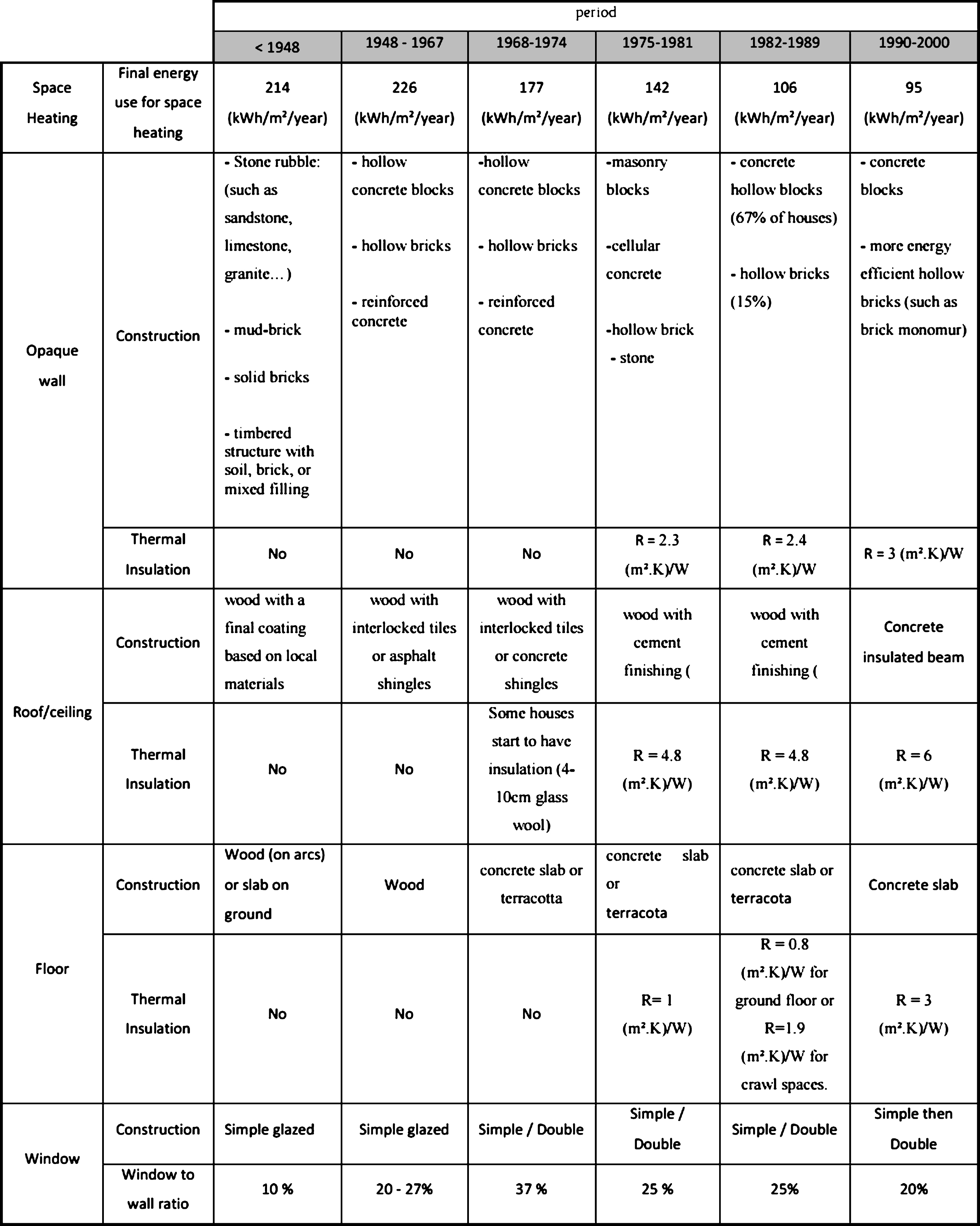
Simulations are carried out, using the EnergyPlus numerical model, for the different construction periods and under different climates of France: Mediterranean, Oceanic, and Semi-Continental. Depending on the construction period, different window-to-wall ratios, wall, roof, and ground insulation thicknesses, air change rates, wall structures, etc. are considered. The envelope construction materials for the different construction periods are presented in Table 1 (DHUP, 2007, 2011). The heating set-point is 19°C.
For the period 1968–1974, we modelled two different houses: the first one “1968–1974(1)” has simple glazed windows and no insulation in the roof; the second one “1968–1974(2)” has double glazed windows and 6 cm thermal insulation in the roof. Also, for the period after 1990, we distinguished two cases: the first one, >1990(1), has the exterior walls composed of concrete structure with 10 cm internal thermal insulation and the second one, >1990(2), has the exterior walls composed of 42 cm of brick-monomur with no internal insulation.
Figure 13 shows the house’s energy load without the aerogel-based rendering (ABR) and with 5 cm ABR on the exterior facades for the different construction periods and for the different climates. For the period 1968–1974, we modelled two different houses: the first one “1968–1974(1)” has simple glazed windows and no insulation in the roof; the second one “1968–1974(2)” has double glazed windows and 6 cm thermal insulation in the roof. Also, for the period after 1990, we distinguished two cases: the first one, >1990(1), has the exterior walls composed of concrete structure with 10 cm internal thermal insulation and the second one, >1990(2), has the exterior walls composed of 42 cm of brick-monomur with no internal insulation. The figure shows that for the old houses built before 1974, the percentages of energy reductions are between 40–68% for the Mediterranean climate, 37–55% for the oceanic climate, and 33–46% for the Semi-Continental climate. It is worth to note that the relative decrease in the heating demand (as percentage from the initial demand) is the highest in the Mediterranean climate; however, the reductions as absolute values are much higher in the other climates.
For the houses built in the period 1975–1989, the reductions are 32%, 23%, and 17% for the Mediterranean, Oceanic, and Semi-Continental climates. Lower reductions are achieved in the new houses, 23%, 14%, and 10% for the three climates, respectively. Since the new houses already have thermal insulation in the exterior envelope, adding the insulating rendering will not decrease the annual load a lot; however, this reduction is still needed to reach the thermal regulations for low energy houses. We can conclude that this rendering is very interesting and beneficial for buildings under rehabilitation, especially the un-insulated houses, where a small thickness can reduce the energy load extensively, which also means conservation of the house’s liveable area. For a medium level insulated house, adding the rendering also has a good advantage. For very well insulated houses, adding the rendering will still reduce the energy load, but certainly its importance lies in achieving more and more energy efficient houses to reach the strict thermal regulations for low energy buildings.
The percentage of occupied time where heating is not needed for different aerogel-based rendering thicknesses for the old house is shown in Figure 14. The occupied time represents the total time (in hours throughout the whole year) when the occupants are actually in the house according to the scenario shown in Figure 4. As the rendering thickness increases, the number of hours where heating is not needed increases. Taking the 5 cm as an illustration, the percentage increases by 10%, 6%, and 3% for the Mediterranean, Oceanic, and Semi-Continental climates, respectively, compared to the house with no rendering.
5Conclusion
In this study, the thermal behaviour of buildings with an advanced thermal insulation system, particularly with the aerogel-based rendering exterior insulation system is examined. In addition to new buildings, the rendering is very suitable for application to retrofit existing ones since it has a high insulation performance and its application is easy, compatible with traditional masonry facades, and using common well-known techniques. Numerical modelling simulations are carried out on three different scales: (a) 1D envelope scale, using the software WUFI, to examine the aerogel rendering’s impact on the thermal and moisture transfer of exterior walls, (b) 2D envelope scale, using an in-house developed MATLAB program, to examine its impact on limiting the heat losses through some types of thermal bridges, and (c) full-scale house, using the software EnergyPlus, to examine its impact on reducing the heating demands.
Results show that adding the aerogel-based rendering on the exterior surface of un-insulated or already internally insulated walls reduces significantly or removes entirely the risk of moisture. It also reduces the wall heat losses significantly, especially for old un-insulated buildings, and consequently the building’s energy consumption. In addition, this insulating rendering can act as a very suitable solution for some thermal bridges such as the window reveals. Due to its application technique and its high insulating performance, a small thickness can have great impact on reducing these heat losses. Thus, this type of insulating renderings/plasters can serve as a good solution for places where traditional insulation is difficult to apply or where small insulation thicknesses are needed due to space or construction constraints.
Acknowledgments
The French FUI financial support (n° F1102029V) and the financial support of PAREX group are highly appreciated. As are all the partners of the PAREX.IT project.
References
1 | ADEME ((2014) ). Buildings. [HTML] Retrieved from http://www2.ademe.fr/servlet/KBaseShow?sort=-1&cid=96&m=3&catid=12846. |
2 | Allinson D. , & Hall M. ((2010) ). Hygrothermal analysis of a stabilized rammed earth test building in the UK. Energy and Buildings, 42: , 845–852. |
3 | ANSI/ASHRAE 140. ((2007) ). Standard Method of Test for the Evaluation of Building Energy Analysis Computer Programs. |
4 | Antretter F. , Sauer F. , Schopfer T. , & Holm A. ((2011) ). Validation of a hygrothermal whole building simulation software proc. of building simulation, in: 12th Conference of International Building Performance Simulation Association, Sydney, pp. 1694–1701. |
5 | Baetens R. , Jelle B. , & Gustavsen A. ((2011) ). Aerogel insulation for building applications: A state-of-the-art review. Energy and Buildings, 43: , 761–769. |
6 | Barbero S. , Marco D. , Ferrua C. , & Pereno A. ((2014) ). Analysis on existent thermal insulating plasters towards innovative applications: Evaluation methodology for a real cost-performance comparison. Energy and Buildings, 77: , 40–47. |
7 | Cuce E. , Cuce P. M. , Wood C. J. , & Riffat S. B. ((2014) ). Toward aerogel based thermal super insulation in buildings: A comprehensive review. Renew Sustain Energy Reviews, 34: , 273–299. |
8 | Delgado J. , Ramos N. , Barreira E. , & de Freitas V. ((2010) ). A critical review of hygrothermal models used in porous building materials. Journal of Porous Media, 13: , 221–234. |
9 | DHUP – Direction de l’habitat, de l’urbanisme et des paysages ((2011) ). Etude socio-technico-économique du gisement de travaux de rénovation énergétique dans le secteur immobilier résidentiel – Outil de modélisation énergétique territoriale ENERTER. |
10 | DHUP – Direction de l’habitat, de l’urbanisme et des paysages ((2007) ). Typologie des bâtiments d’habitation existant en France. |
11 | Energy Efficiency Watch ((2013) ) Final Report: Improving and implementing national energy efficiency strategies in the EU framework. |
12 | EN ISO 10211 ((2007) ). Thermal bridges in building construction–Heat flows and surface temperatures – Detailed calculations. |
13 | Enkvist P. , Naucler T. , & Rosander J. ((2007) ). A cost curve for house gas reduction. The McKinsey Quarterly, 1. |
14 | EN Standard 15026 ((2007) ). Hygrothermal performance of building components and building elements. Assessment of moisture transfer by numerical simulation. |
15 | IBP ((2011) ). WUFI® Pro version 5.1. Holzkirchen, Germany: Fraunhofer Institute for Building Physics. http://www.WUFI.de/index_e.html. (15 January 2013). |
16 | Ibrahim M. , Biwole P. , Achard P. , Wurtz E. , & Ansart G. , ((2015) a). Building envelope with a new aerogel-based insulating rendering: Experimental and numerical study, cost analysis, and thickness optimization. Applied Energy, 159: , 490–501. |
17 | Ibrahim M. , Biwole P. H. , Achard P. , & Wurtz E. ((2015) b). Aerogel-based materials for improving the building envelope’s thermal behavior: A brief review with a focus on a new aerogel-based rendering. Energy Sustainability Through Green Energy, 163–188. |
18 | Ibrahim M. , Wurtz E. , Biwole P. H. , & Achard P. ((2014) a). Transferring the south solar energy to the north facade through embedded water pipes. Energy. 78: , 834–845. |
19 | Ibrahim M. , Wurtz E. , Biwole P. H. , Achard P. , & Sallee H. ((2014) b). Hygrothermal performance of exterior walls covered with aerogel-based insulating rendering. Energy and Buildings, 84: , 241–251. |
20 | Ibrahim M. , Biwole P. H. , Wurtz E. , & Achard P. ((2014) c). Limiting windows offset thermal bridge losses using a new insulating coating. Applied Energy, 123: , 220–223. |
21 | Kalamees T. , & Vinha J. ((2003) ). Hygrothermal calculations and laboratory tests on timber-framed wall structures. Building and Environment, 38: , 689–697. |
22 | Koebel M. , Rigacci A. , & Achard P. . Aerogels for Superinsulation: A synoptic view, Chapter 26, p 611, in “Aerogels Handbook ((2011) ), editors: Aegerter M. , Leventis N. , and Koebel M. ”. |
23 | Koebel M. , Rigacci A. , & Achard P. ((2012) ). Aerogel-based thermal superinsulation: An overview. J Sol-Gel Sci Technol, 63: , 315–339. |
24 | Mantha P. , & Arena L. B. ((2012) ). A systematic approach to hygrothermal modeling and compliance with failure criteria using WUFI®, in: Fifth National Conference of IBPSA-USA, Madison, WI. |
25 | Reim M. , Beck A. , Korner W. , Petricevic R. , Glora M. , Weth L. , Schliermann T. , Fricke J. , Schmidt Ch. , & Pötter F. ((2002) ). Highly insulation aerogel glazing for solar energy use. Solar Energy, 72: ((1) ), 21–29. |
26 | Reim M. , Korner W. , Manara J. , Korder S. , Arduini-Schuster M. , Ebert H. P. , & Fricke J. ((2005) ). Silica aerogel granulate material for thermal insulation and daylighting. Solar Energy, 79: , 131–139. |
27 | Seem J. E. ((1987) ). Modeling of heat transfer in building. PhD Thesis. University of Wisconsin-Madison, USA. |
28 | Soleimani Dorcheh A. , & Abbasi M. H. ((2007) ). Silica aerogel: Synthesis, properties and characterization. Journal of Materials Processing Technology, 199: (1-3), 10–26. |
29 | VDI Richtlinie 6020. ((2001) ). Anforderung an Rechenverfahren zur Gebäude- und Anlagensimulation. VDI-Verlag GmbH, Düsseldorf, Berlin. |
30 | Verbeeck G. , & Hens H. ((2004) ). Energy savings in retrofitted dwellings: Economically viable? Energy & Building, 37: (7) 747–754. |
31 | Walton G. N. ((1983) ). Thermal analysis research program reference manual. NBSSIR 83-2655. National Bureau of Standards. |
32 | US Department of Energy, EnergyPlus v. 7.0.0. ((2011) ). Energy Efficiency and Renewable Energy Office, Building Technology Program. http://apps1.eere.energy.gov/buildings/energyplus/ |
33 | US Department of Energy, EnergyPlus Input-Ouput reference (page 17) (2014). Retrieved from: http://apps1.eere.energy.gov/buildings/energyplus/pdfs/inputoutputreference.pdf (Date of last access: April 2015). |
Figures and Tables
Fig.1
Comparison of the thickness required to retrofit an old exterior envelope from an initial U-value of 6.4 W/(m2 K) to a target U-value of 0.4 W/(m2 K) with different insulating materials (Ibrahim et al., 2015a).
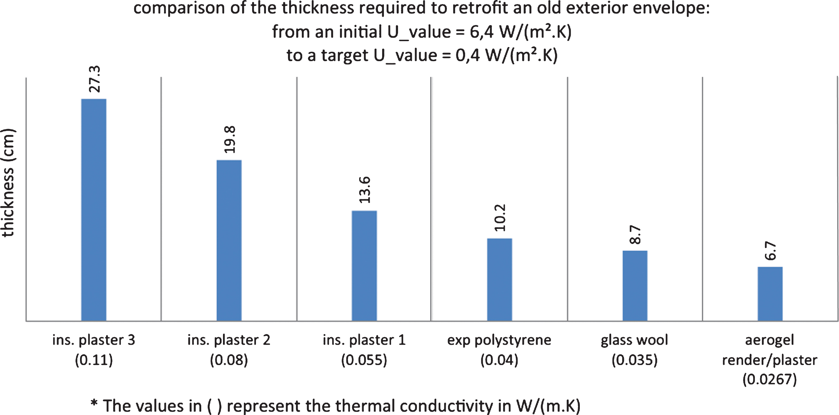
Fig.2
Typical control volume numerical discretization.
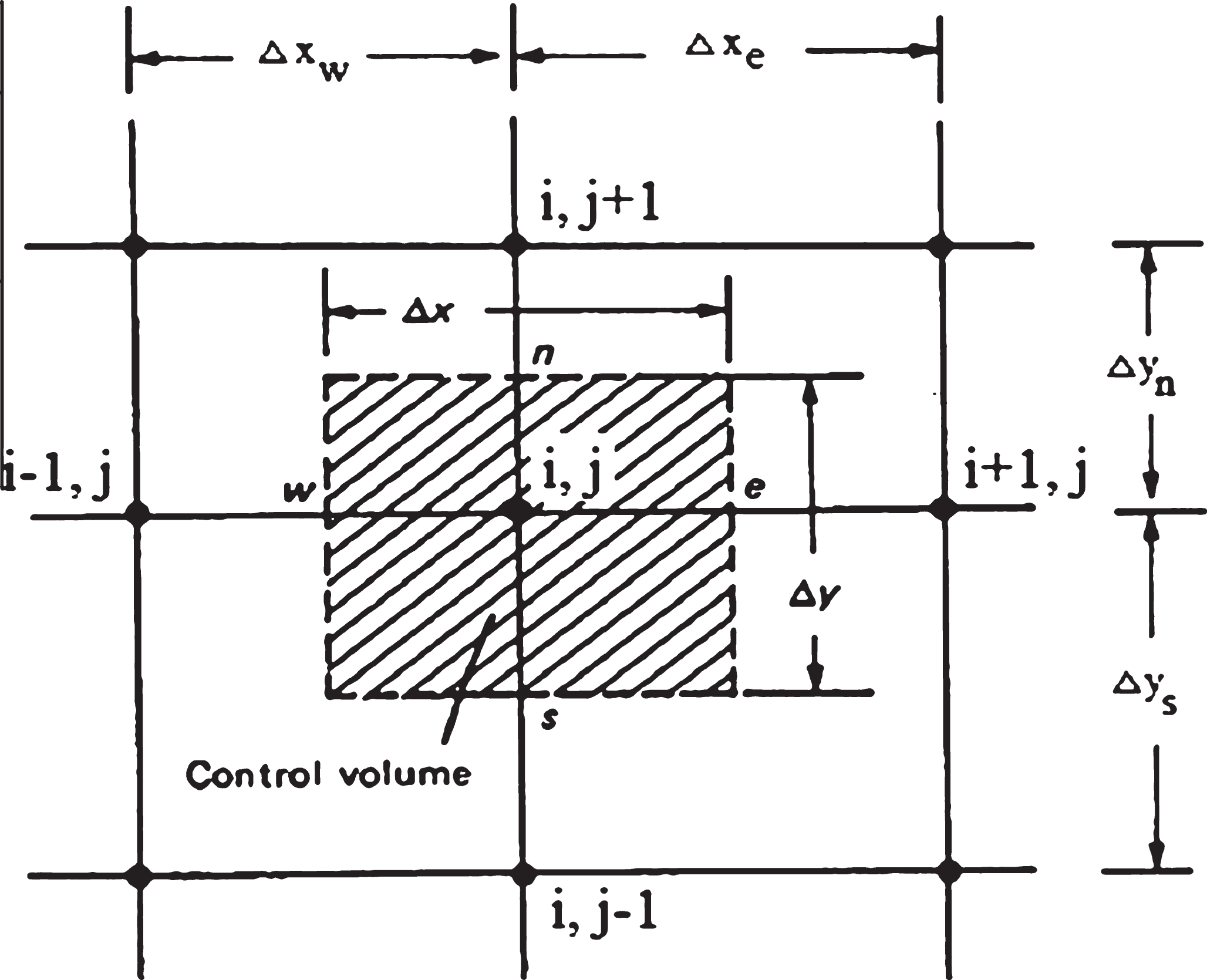
Fig.3
The modelled house, south-west view (left) and north-east view (right).
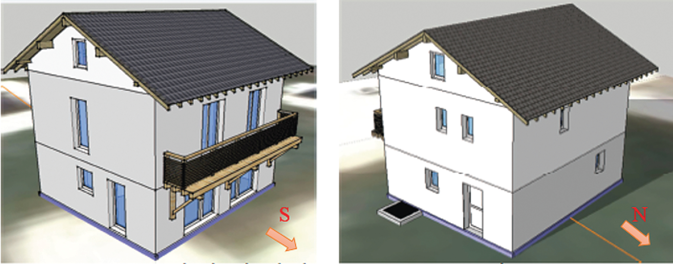
Fig.4
Occupancy scenario in the numerical model.
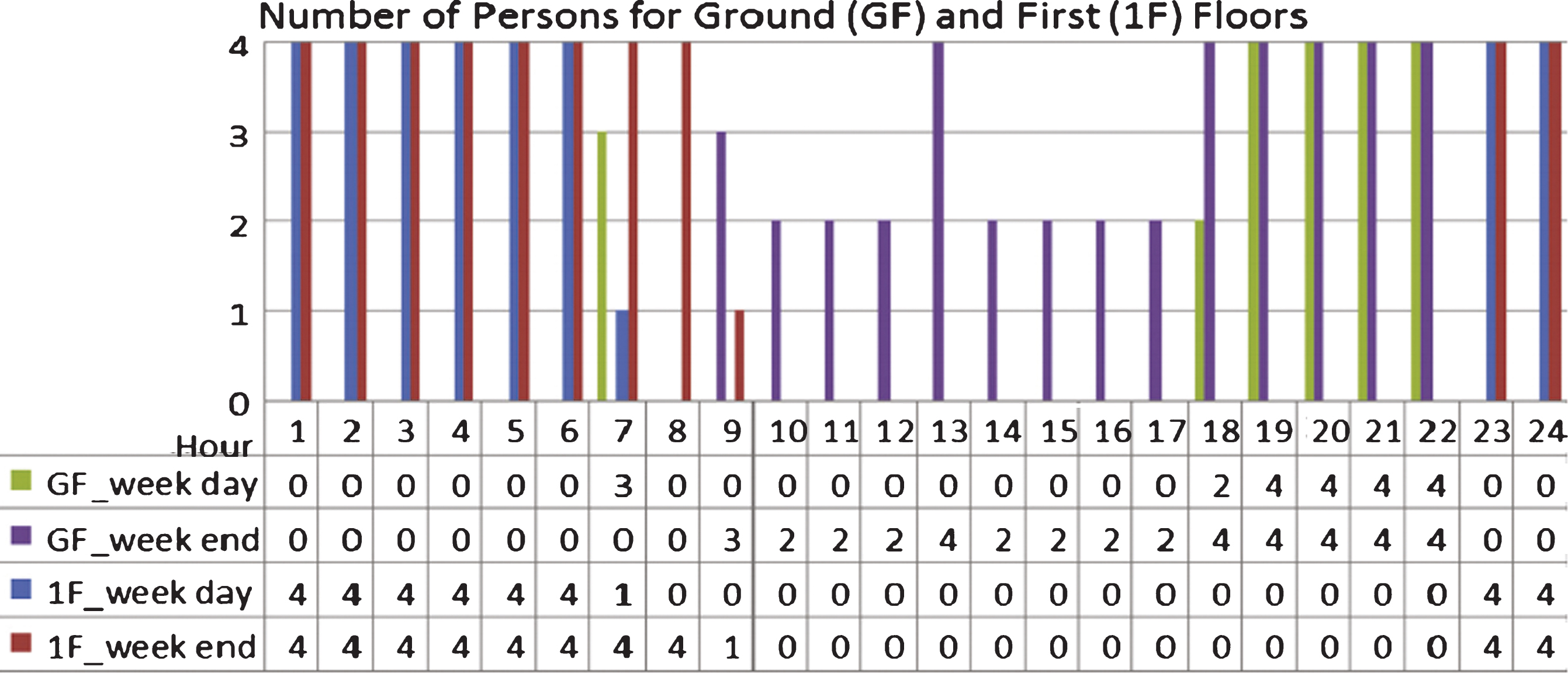
Fig.5
Equipment load scenario in the numerical model.
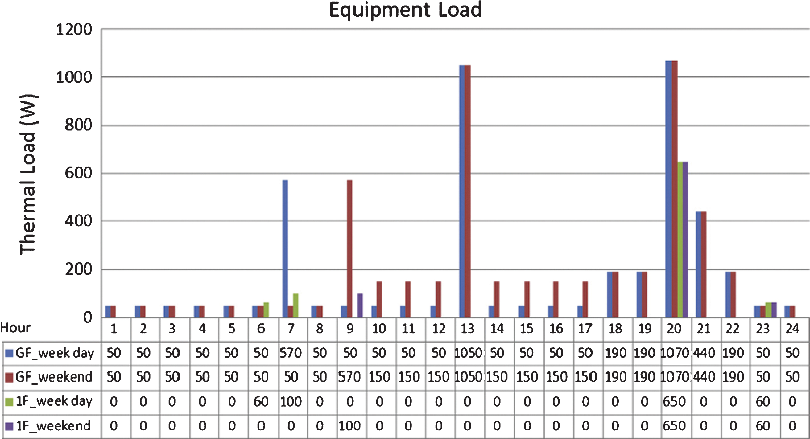
Fig.6
Exterior and interior air temperature and relative humidity over one year for Grenoble.
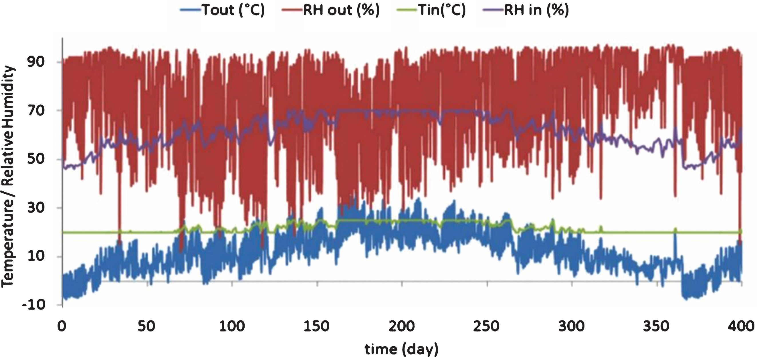
Fig.7
Evolution of the total water content over the 4 years for the different insulation configurations.
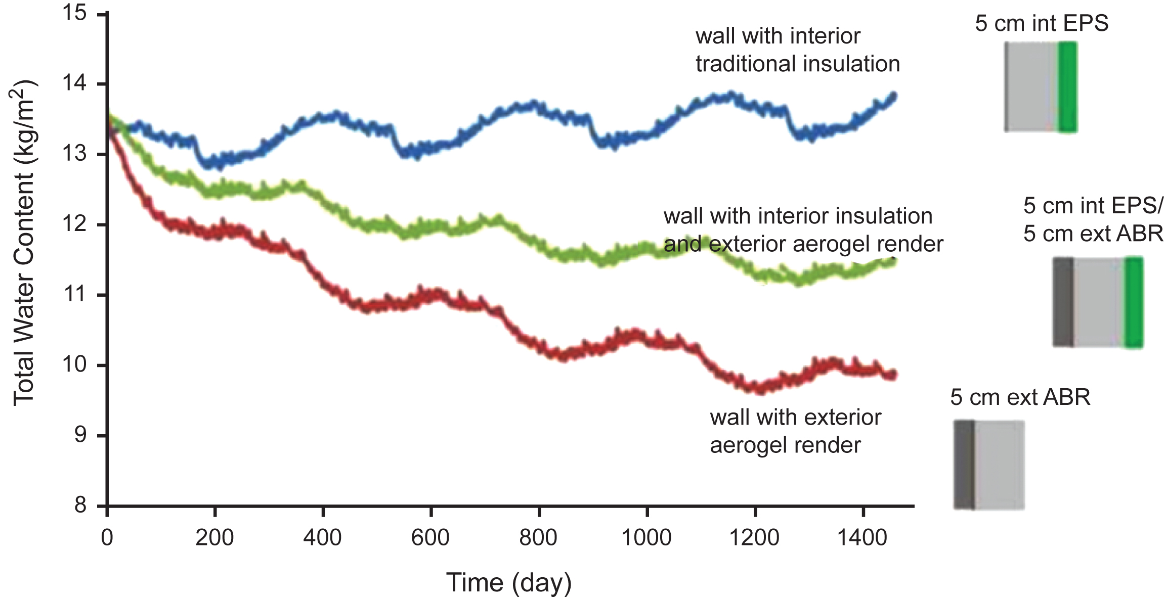
Fig.8
Wall heat losses for different insulation configurations and materials.
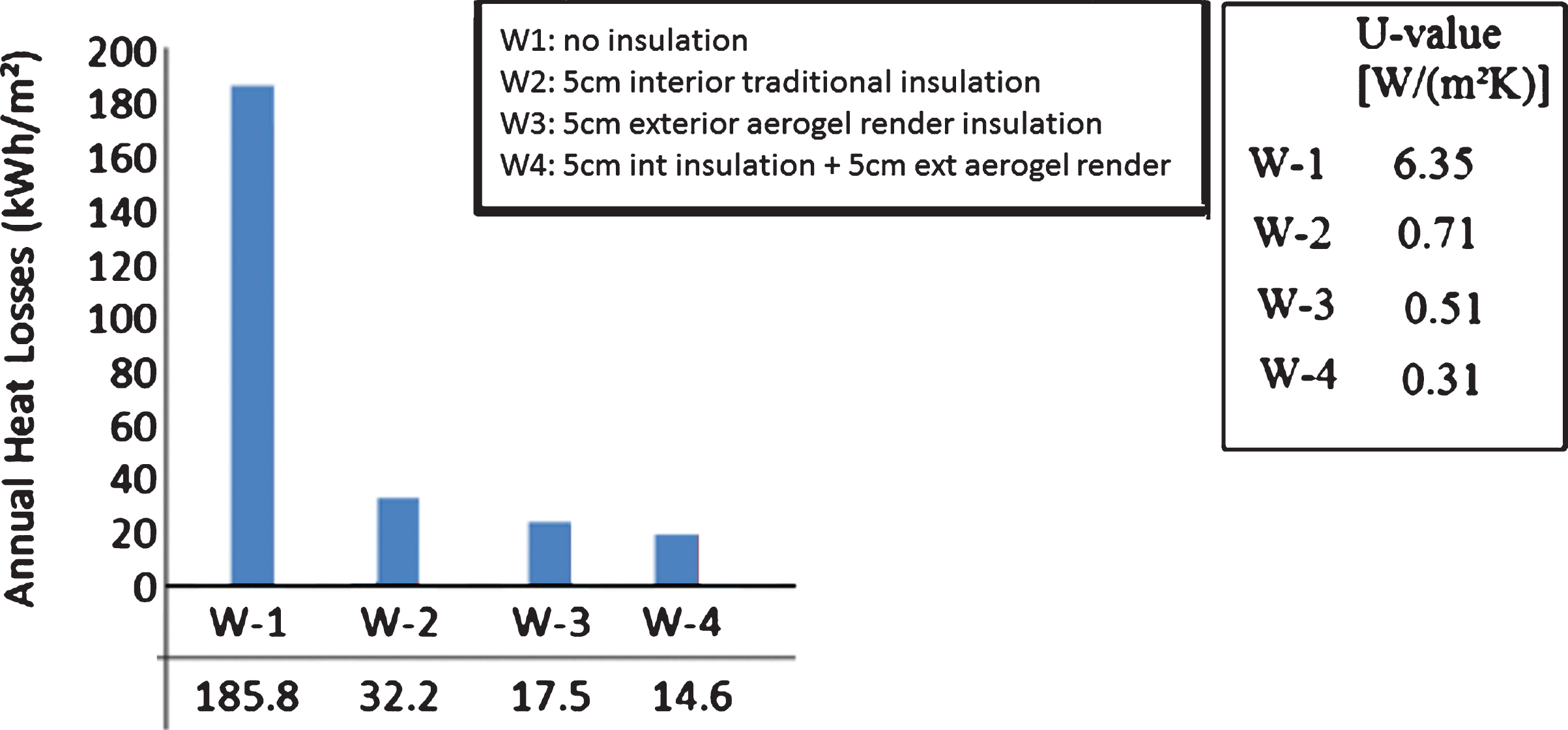
Fig.9
Thermal bridge heat losses through wall/floor junction (left) and window reveal (right).
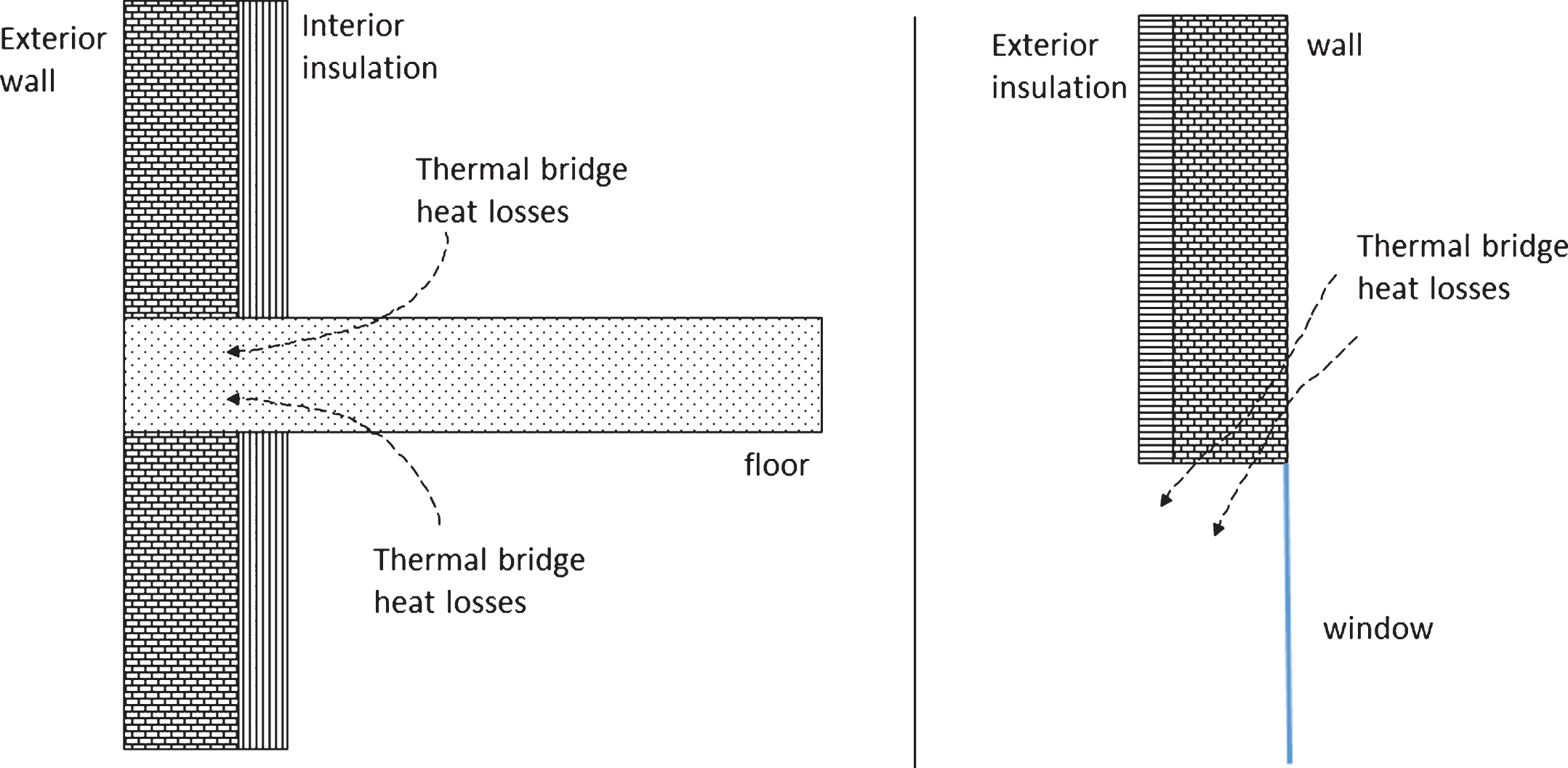
Fig.10
Wall (with 4 cm interior insulation) heat losses for a wall-floor junction for different exterior aerogel rendering’s thicknesses.
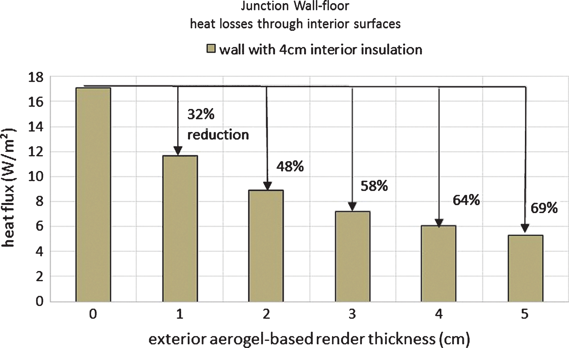
Fig.11
Window reveal heat losses for a wall with 5 cm exterior insulation and for no, 1 cm, and 2 cm aerogel rendering on the window reveal edge.
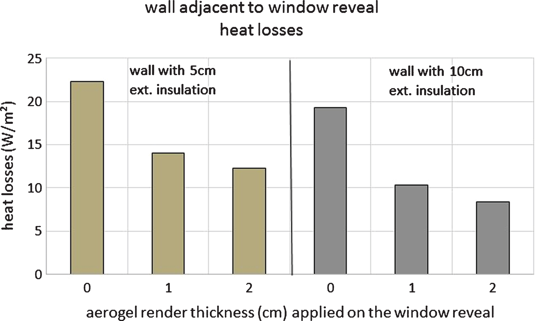
Fig.12
Heat losses magnitudes through the window reveal for a window edge with no aerogel rendering (left) and with 1 cm aerogel rendering (right).
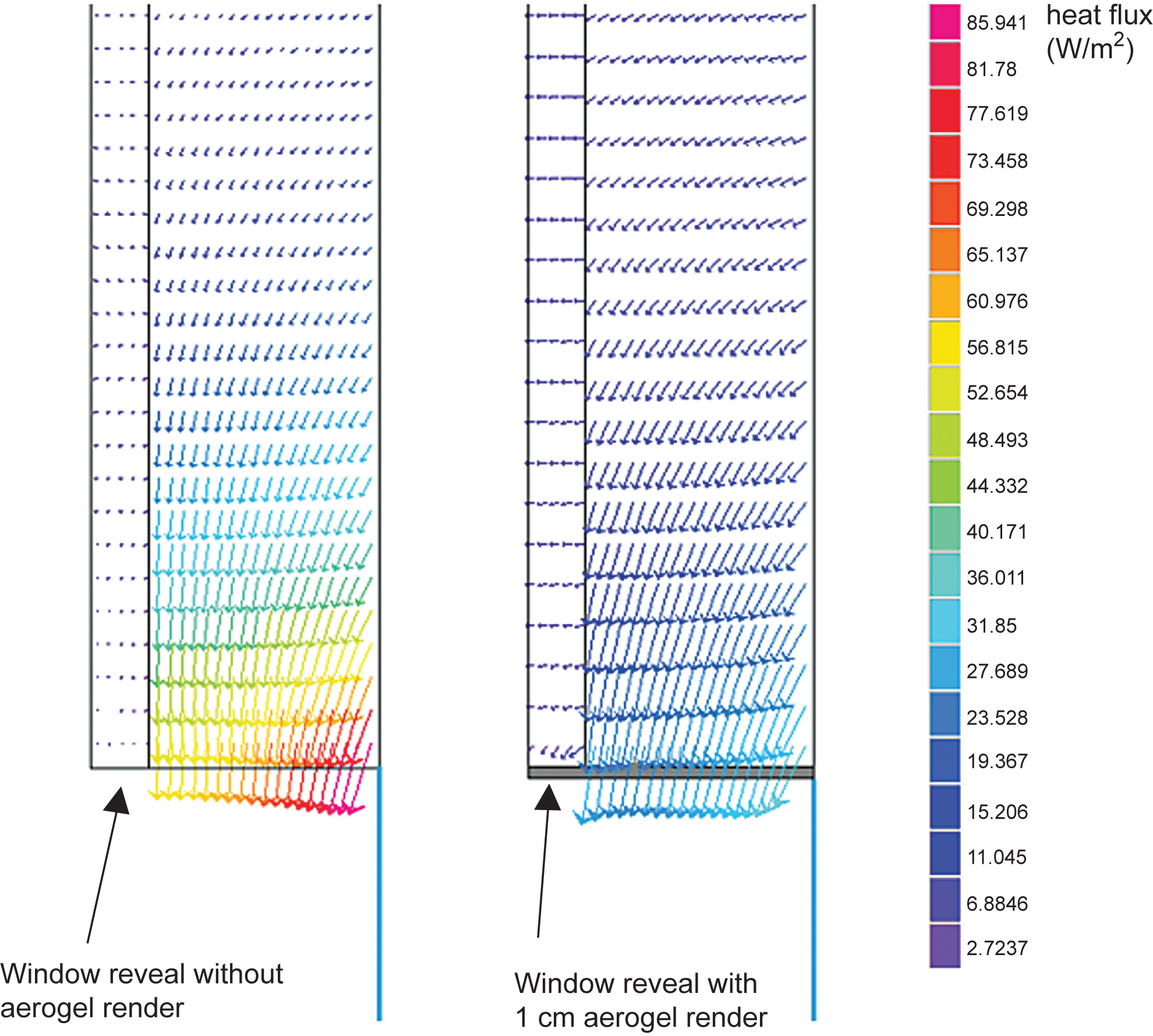
Fig.13
Annual heating load for the different climates and the different construction periods with and without the rendering.
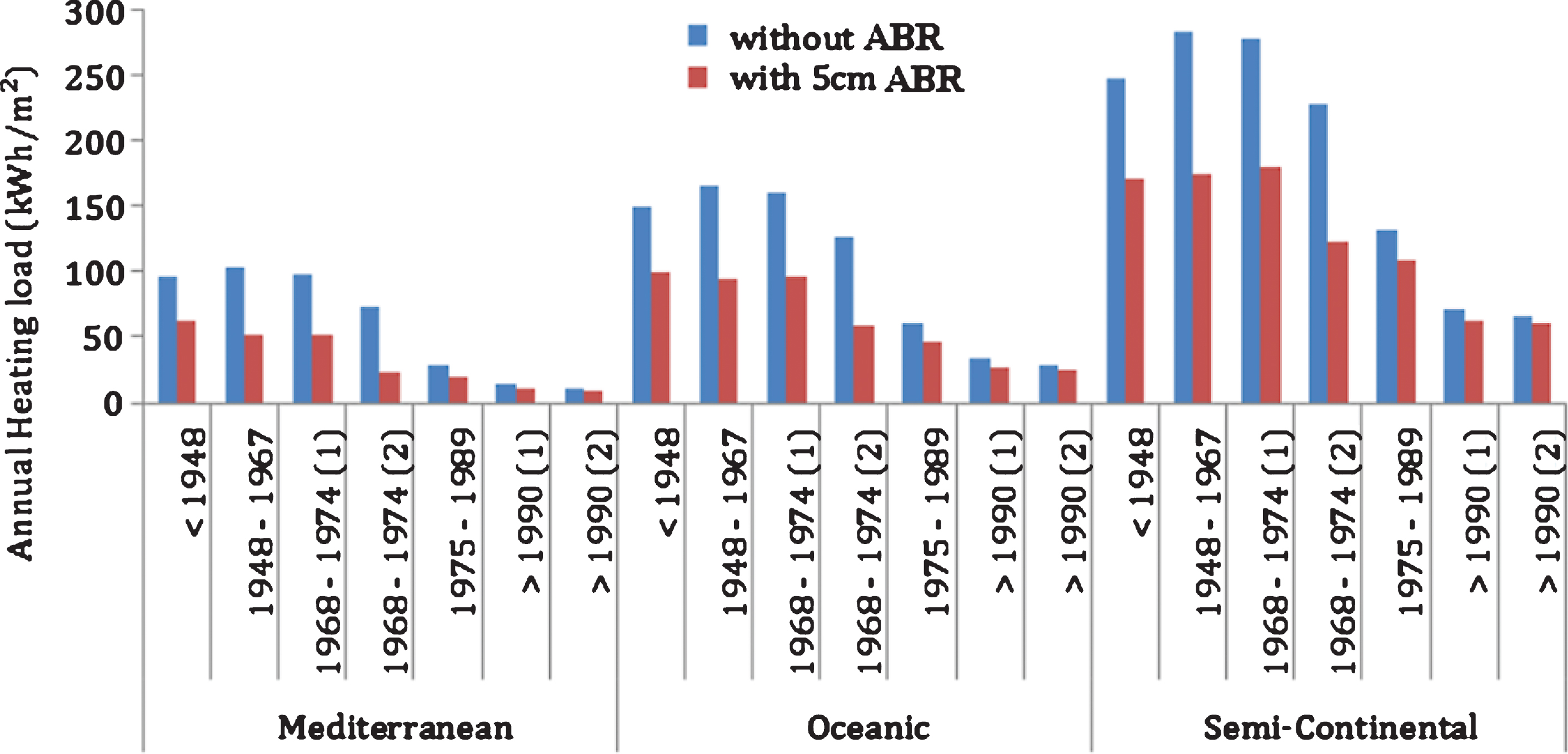
Fig.14
The percentage of occupied time where heating is not needed for different aerogel-based rendering thicknesses for the old house under different climates.
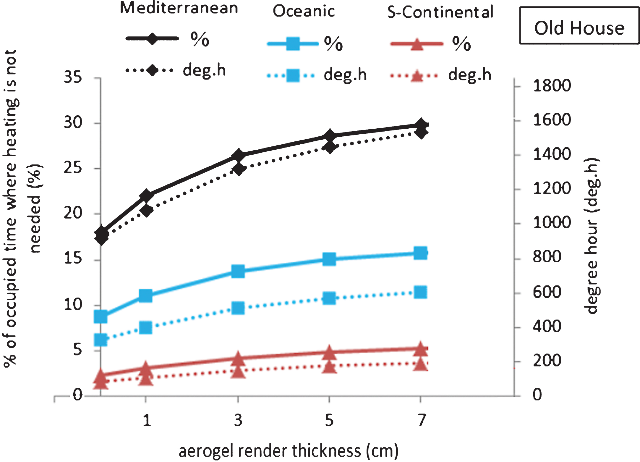
Table 1
Houses’ construction materials in France during the different periods (DHUP, 2007, 2011)
 |

