
Full-scale performance testing and evaluation of unitized curtain walls
Abstract
Unitized curtain wall systems have been widely seen on high-rise buildings’ facades by bringing benefits with regard to ease of construction, lightness, etc. However, some design and application problems related to structural and infiltration performance of a facade system might arise during its life cycle, which is difficult for the building to compensate. This paper presents a comparative analysis of the structural and infiltration performance of the two identically detailed and produced unitized curtain wall system mock-ups. In order to understand long-term environmental effects on the curtain wall system, a fatigue process was applied on one system in addition to the standard test procedures, while the standard test procedure was applied on the other reference specimen. The tests on the two identical specimens were conducted in accordance with TS EN 13830 and AAMA 501.4 Standards. As a result of air infiltration and wind load resistance tests, air infiltration and frontal deflection values on the facade surface were obtained. Hence, experimental performance of the systems was compared and the effect of the fatigue procedure on the facade performance was evaluated.
1Introduction
Recent curtain wall applications in the building construction sector show that unitized curtain wall system becomes more preferable by architects and system manufacturers especially for high-rise buildings, owing to the advantages with regard to the ease of construction, lightness, weather tightness, quality detailing, thermal performance, etc. Unitized systems enable straightforward processing by means of serial production and pre-assembly of the individual facade units. Most of the system components are assembled in a plant under controlled working conditions, promoting quality assembly and allowing for fabrication lead-time and rapid closure of the building without being affected by weather conditions (Horowitz, 1991). Right along with the advantages of the unitized curtain walls, some design and application problems related to the structural and infiltration performances might arise during their life cycle. Repeated variable wind loads and climatic conditions are the most significant factors affecting the long-term structural and infiltration performances. Experiences verify that the criteria such as structural integrity, provision for movement, and weather tightness are of great importance during their design. Certainly, there are a number of other considerations, most of which are of less critical importance and some of which vary in importance depending on the location and type of building (Wong, 2007).
Curtain wall construction has stimulated the development of the most significant test programs. Programmed testing has become a requirement on curtain wall mock-ups for air-leakage, water leakage, structural strength, thermal performance and further testing for capabilities such as seismic, acoustical, dust or snow performances. Full-scale preconstruction curtain wall mock-up testing is today normally considered a standard practice for buildings where the curtain wall is a custom application for high-rise buildings, and for buildings where a high confidence level is desired. Curtain wall mock-up tests comprise a full size representative portion of the proposed exterior wall system along with the simulated environmental conditions, such as wind, temperature extremes, and seismic exposure. Standard test methods, however, may not be sufficient to specify all the requirements for a mock-up test program with regard to some performance assessment. For example, there is no standard test procedure to assess the long-term performance of curtain wall systems (Sakhnovsky, 1991; Kasket et al., 1998). Mock-up tests provide an indication of the performance of the curtain wall only at the time it is brand-new. Workmanship quality of the mock-up is usually very good because every element is constructed under a thorough inspection that is not expected during construction of the curtain wall on the building. Whether through aging or because of sealant related problems, most curtain wall systems let some water enter, which causes decrease on the structural and infiltration performance (Sakhnovsky, 1991).
This paper presents the test procedures for evaluating long-term structural and weather (air, water) infiltration performances of unitized curtain wall systems. In order to reach this objective, full-scale mock-up testing of two identical unitized curtain wall panels was carried out. During the testing process, one specimen was subjected to fatigue process before conducting the standard test procedures while only the standard test procedures were applied on the other identical specimen. Experimental performances of the two specimens were compared.
2Experimental process
As is customary, for approval of the facade for a specific project, a series of various performance tests must be carried out before starting the production and the site erection. All these performance tests, that can help to increase the probability of trouble-free performance of the wall on the completed building, are conducted on a 1:1 scale model of the facade, having exactly the same characteristics of the real final product (Galli, 2011). Performance testing of the specimen, both prior to construction and during construction, is a well-established and respected element of quality assurance. Testing representative segments of curtain wall, or windows, for example, comprises three basic tests such as air infiltration, water penetration, and structural loading. When the systems succeed the performance tests, the system can be accepted to fulfil the requirements of water penetration, strength, air infiltration, seismic performance, etc. that ensure the quality.
2.1Mock-up design
The experimental study was carried out on a large test rig located at the Facade Testing Institute, Istanbul (Fig. 1a and b). The test specimens shown in Fig. 1, consist of two identically detailed unitized curtain wall systems with 2,40 m width, 4,45 m height dimensions, and are comprised of aluminum framing members and insulating glass units. 4 mm clear float and 8 mm tempered glass double-glazing units with structural silicone spacer were used for the transparent parts. Total surface area of each specimen is 10,68 m2, see Fig. 1c. Specimen P is the reference specimen and Specimen FP is the one that the fatigue procedure was applied on to investigate the long-term environmental effects (Ilter et al., 2014). The main difference between the two specimens is that the water penetration under dynamic pressure and fatigue procedure tests were additionally conducted on Specimen FP besides the standard test procedure.
2.2Performance tests
The commonly used performance tests, which are static air infiltration, water penetration under static and dynamic pressures, wind resistance for design load and safety requirement, seismic resistance and fatigue process are explained below with respect to the related norms. In addition to them, acoustic performance, impact resistance of glass, thermal cycling tests are also conducted on curtain wall systems in Turkey but these tests are out of the scope of this study.
Air infiltration test under static pressure: Using the chamber developed for the mock-up testing, the rate of air leakage through the specimens is determined at the project specified pressure differential induced across the assemblies. The air leakage rates determined are compared against the acceptable rates identified for the project. Prior to testing, the specimens’ exterior faces are covered with a watertight steel plate. Subsequently, the specimens are subjected to the positive and negative pressure of 660 Pa (more than 10% of normal pressure value) by holding for 3 seconds, and then released. Air infiltration is tested up to a test pressure of 600 Pa by increasing with steps of 50, 100, 150, 200, 250, 300, 450, 600 Pa (TS EN 12153, 2004).
Water penetration test under static pressure: A pressure differential is applied across the curtain wall assembly, while simultaneously applying water spray onto the exterior surfaces. The testing is performed to show the water penetration resistance of the curtain wall systems and transitions between the system components. Static water penetration tests are conducted at a flow rate of 3.4 lt/(m²·min) at up to a test pressure of 600 Pa according to TS EN 12155 standard. Specimens are subjected to 660 Pa positive pressures and held for 3 seconds, then released. Afterwards, considered pressures of 50, 100, 150, 200, 250, 300, 450, 600 Pa are applied to the specimens and held for 300 seconds per each pressure step (AAMA 501.1, 2005). Negative and positive wind pressures are applied on the exterior face of the panel during the testing.
Water penetration test under dynamic pressure: Water penetration testing consists of utilizing a portable wind generator and installing a spray rack system at the exterior of the specimen. A ROTAX Airplane engine equipped with 1850 mm diameter propeller producing 1350 Pa (165 km/h) wind velocity was used. The engine and prop assembly are mounted into a steel frame that incorporates a sheet metal shroud and lifting fixture. Dynamic wind stream has been generated along with the water spray perpendicular to the outdoor face of the specimen for a period of fifteen minutes, right along with the water applied at the rate of 3.4 lt/(m²·min) on the face completely and continuously, see Fig. 2 (TS EN 12179, 2000).
Wind resistance test based on design load and safety requirements: The test is conducted through Turkish Standards; TS EN 13116 describes performance requirements due to design load while TS EN 12179 specifies the method to determine the performance of curtain wall components under positive and negative static air pressure regarding the safety issues. Positive test pressure is conducted before the negative test pressure. Prior to testing, three measurement points were determined. M1 and M3 were at the level of structural supports on the middle axis while M2 was in the middle of M1 and M3 (Fig. 1c). The specimens are subjected to 1200 Pa (50% of the design load) positive and negative pressures, held for three seconds, and then released. Afterwards, pressures with increasing steps of 0, 600, 1200, 1800, 2400 Pa are applied to the specimens and held for 10 seconds for each pressure step. Lateral deflections were measured at positive and negative wind pressures up to ± 2400 Pa. Frontal deflections of the specimens were determined according to TS EN 13116. At the beginning of the test three pulses of air pressure (50% of design wind load or 500 Pa whichever is greater) is applied. Then, the sample is subjected to 25% , 50% , 75% , and 100% of design wind load. The test specimens are exposed to positive and negative wind loads by applying 150% of the design load (PE = ± 3600 Pa) (AAMA, 2009, TS EN 12155, 2005).
Seismic resistance test: This test provides performance evaluation of curtain wall systems when subjected to the specified horizontal displacements representing an earthquake. Furthermore, it is intended to analyze the seismic safety of architectural glass components within a curtain wall. The static test method is conducted through AAMA 501.4, which is applied on the same test chamber with air infiltration, water-tightness, and wind resistance. Testing is done by means of a bottom structural support unit for producing horizontal movements and completed at three full cycles where a cycle is defined as a full displacement in one direction, back to the originating point, full displacement in the opposite direction and back to the originating point. Each cycle is completed in almost 2 minutes. The design displacement is taken as 34 mm (0.010×the greater of the adjacent story height), and measured at the movable structural support unit. After the tests, all areas were inspected in detail, and no disengagement, metal distortion, sealant or glazing failures were observed (TS EN 12155, 2005).
Fatigue procedure: Uniformly distributed suction loads were applied on the outer surface of the specimen. ETAG 17 comprises a static wind suction test, which is applied to specimens for the fatigue procedure. The test was performed in successive steps of 500 Pa to 3500 Pa (lower than the extreme load pressure: 3600 Pa) with a return to zero at each level, and loads were held for 10 seconds per each pressure step. The results of the fatigue test are given in Fig. 3.
For the two specimens, test sequence was determined according to TS EN 13830 and AAMA 501.4. The tests were conducted at three phases during nine months with 90 days intervals between each testing sequence. In total, six test sequences were conducted on the reference Specimen P and fatigued Specimen FP. The categories of the tests for P are air infiltration, water penetration under static pressure, wind resistance, seismic resistance as the standard tests. Water penetration under dynamic pressure tests and fatigue procedure were the additional tests for FP along with the standard tests. Although the design load value (PD, ± 2400 Pa) was defined by the manufacturer, normal pressure value (PN; % 25 of PD, ± 600 Pa) and extreme wind (safety) load (PE; % 150 of PD, ± 3600 Pa) were calculated according to TS EN 12154 and TS EN 12179. The applied test sequence in order is given in Table 2.
3Test results and performance evaluation
This experimental work revealed that the measured maximum air infiltration values were within the acceptable limits (i.e. 1.50 m³/m²·h) for the reference Specimen P on which the fatigue process was not applied during all three testing phases. However, the air infiltration values highly increased and reached 2.31 m³/m²·h for positive pressure and 2.04 m³/m²·h for negative pressure after the fatigue process was conducted in FP. The fatigue process was applied till the last testing phase. Water leakage was not observed in P at the end of the three testing phases, while water leakage was observed in FP after the second and third testing phases showing that the fatigue process caused loss of performance on the curtain wall system as expected, see Table 1. The water was observed at the intersection of the four panel pieces (A and C) on the vertical axis of the curtain wall panel, indicated as W1 (Fig. 1c).
Frontal lateral deflection values from wind loading increased at each testing phase, however some values slightly exceeded the limit of 15 mm at high negative pressure values while the positive deflections were within the acceptable limits. Results show that, as expected, the overall stiffness of the tested panel is higher for positive pressures than negative pressures (Table 1). Test sequence and infiltration and structural tests results were grouped with regard to the available standards for performance classification (Table 2). The experimental results attained are demonstrated by the infiltration and structural performance criteria, which were numerically obtained with the tests for performance evaluation.
It is a crucial issue for the facade manufacturer, owner or contractor, and designer to evaluate the long-term performance of a facade system. Tables 1 and 2, and Fig. 4 show that, at the maximum wind pressure of 2400 Pa, frontal deflections are exceeded by 6.67% and 18.53% for P and FP, respectively. Air infiltration values for FP are measured as 2.31 m³/m²·h and 2.04 m³/m²·h at the third testing phase. These values exceeded the acceptable limits by 54% and 36% in positive and negative loading type respectively while the air infiltration values of P are within the acceptable limits at all testing phases.
4Conclusions
The following results can be drawn from this full-scale experimental work:
• Although the majority of today’s unitized curtain wall systems is technologically improved and performs higher requirements, the test results indicate that the continuous impact of environmentalconditions cause a significant loss in performance (up to 54% due to air infiltration, 18.53% due to wind pressure) during the curtain wall system’s life time.
• The most critical criterion seemed to be the frontal deflections in P while water leakage limit was exceeded first in FP in addition to exceedance limits of air infiltration and frontal deflections.
• Considering that the recent test procedures provide an indication of the curtain wall only at the time when it is brand-new, test procedures which evaluate real life performance of the curtain wall systems should be developed for more realistic evaluations.
• The process of mock-up testing plays an important role towards understanding the performance of the curtain wall system regarding the critical issues. However, whole experiment process requires experience, time, high efforts and cost issues.
Acknowledgments
This experimental research was fully supported by Façade Testing Institute (FTI) and Metal Yapı A.Ş., Istanbul. This support is gratefully appreciated. However, any opinions, findings, conclusions, and recommendations presented in this paper are those of the authors and do not necessarily reflect the views of the sponsors.
Reference
1 | AAMA(2005) Standard Test Method for Water Penetration of Windows, Curtain Walls and Doors using Dynamic PressureArchitectural Manufacturers AssociationUSA |
2 | AAMA(2009) Recommended Static Testing Method for Evaluating Curtain Wall and Storefront Systems Subjected to Seismic and Wind Induced Interstory DriftArchitectural Manufacturers AssociationUSA |
3 | ETAG(2006) Standard for Systemized Building EnvelopesCentre for Window and Cladding Technology - CWCTUK |
4 | Galli U(2011) Seismic Behavior of Curtain Wall Facades. A Comparison Between Experimental Mock-Up Test and Finite Element Method AnalysisPolitechnico di MilanoDoctoral Dissertation |
5 | Horowitz J(1991) The Interrelation of Exterior Wall and Structural Systems in Buildings, Exterior Wall Systems-Glass and Concrete Technology, Design and ConstructionBarry Donaldson, ASTM STP |
6 | Ilter E, Tavil A, Celik CO, Seyhan M(2014) Full-Scale Performance Testing of Unitized Facade SystemsICBEST 2014Aachen, Germany |
7 | Kaskel BS(1998) Critical Review of Curtain Wall Mockup Testing for Water PenetrationWater Leakage Through Building FacadesKudder RJ, Erdly JLASTM STP 1314 |
8 | Sakhnovsky, A. A. (1991). Full-Scale Performance Testing of Curtain Walls. Exterior Wall Systems-Glass and Concrete Technology, Design and Construction. Edited by B. Donaldson, ASTM STP 1034 |
9 | TS EN 12179 (2000). Curtain Walling, Resistance to Wind Load/Test Method. Turkish Standards Institution, Ankara, Turkey. (Classification standard: TS EN 13116, Curtain Walling, Resistance to Wind Load/Performance Requirements, Turkish Standards Institution, Ankara, 2004). |
10 | TS EN 12153 (2004). Curtain Walling, Air Permeability/Test Method. Turkish Standards Institution. Ankara, Turkey. (Classification standard: TS EN 12152, Curtain Walling, Air Permeability/Performance Requirements and Classification, Turkish Standards Institution, Ankara, 2004). |
11 | TS EN 12155 (2005). Curtain Walling, Watertightness/Laboratory Test Under Static Pressure. Turkish Standards Institution, Ankara, Turkey. (Classification standard: TS EN 12154, Curtain Walling, Water-tightness/Performance Requirements and Classification, Turkish Standards Institution, Ankara, 2004). |
12 | Wong W(2007) Analysis and Design of Curtain Wall Systems for High Rise BuildingsUniversity of Southern Queensland Faculty of Engineering and SurveyingAustralia |
Figures and Tables
Fig.1
Mock-up Design (1:1 Scale). a: Panel mounted in test rig (interior face). b: Exterior face of the panel. c: Specimen geometry, applied static pressures and measurement points (M1, M2, M3 and cross-sections A-B).
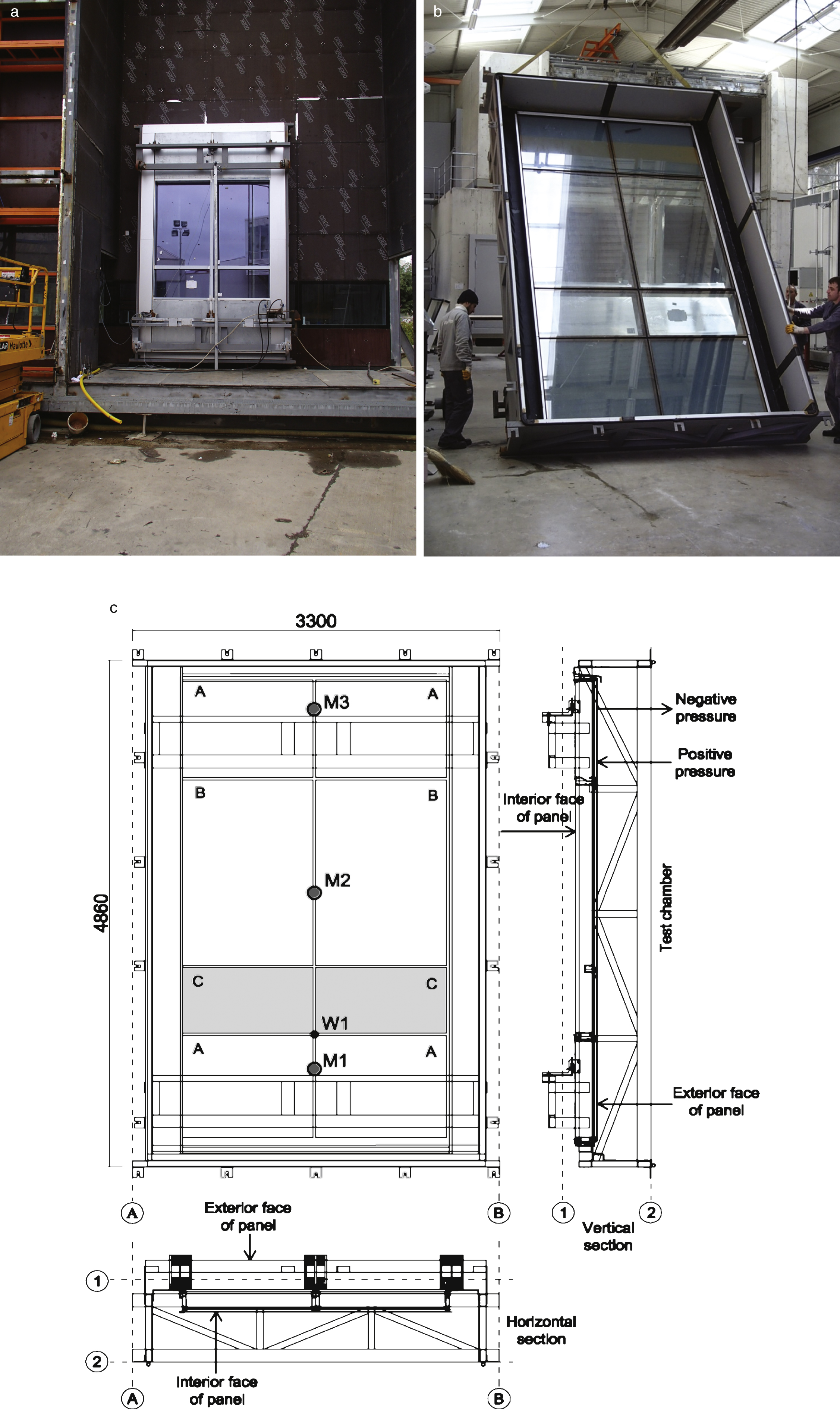
Fig.2
Dynamic water penetration test for the fatigue process.
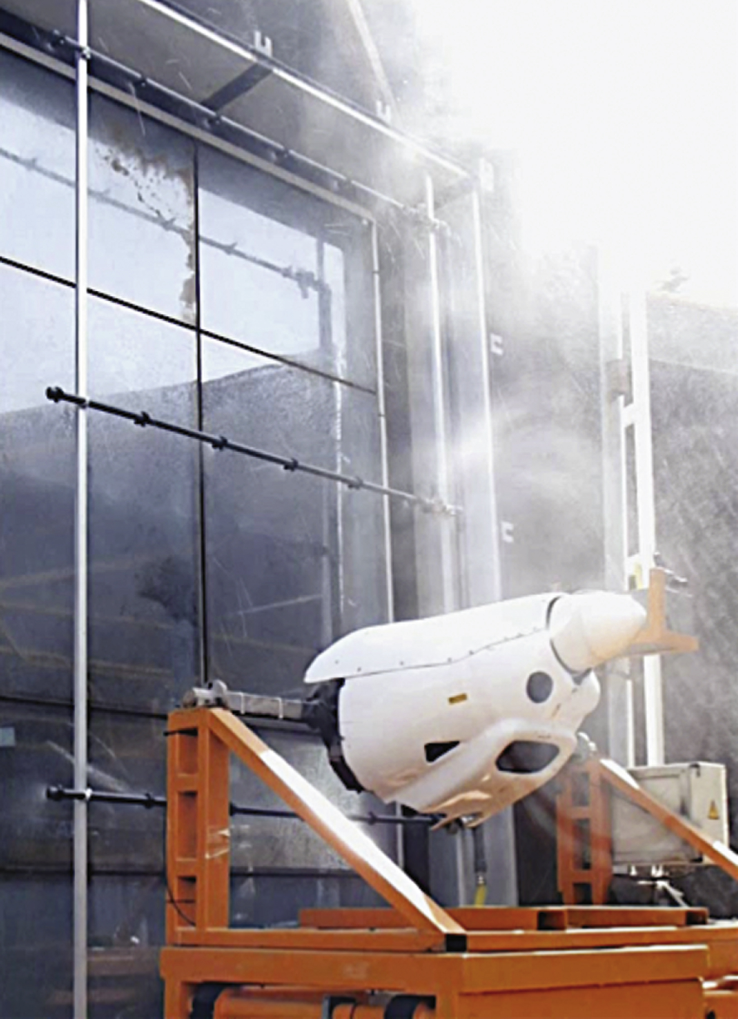
Fig.3
Fatigue procedure applied on the Specimen FP (ETAG 17).
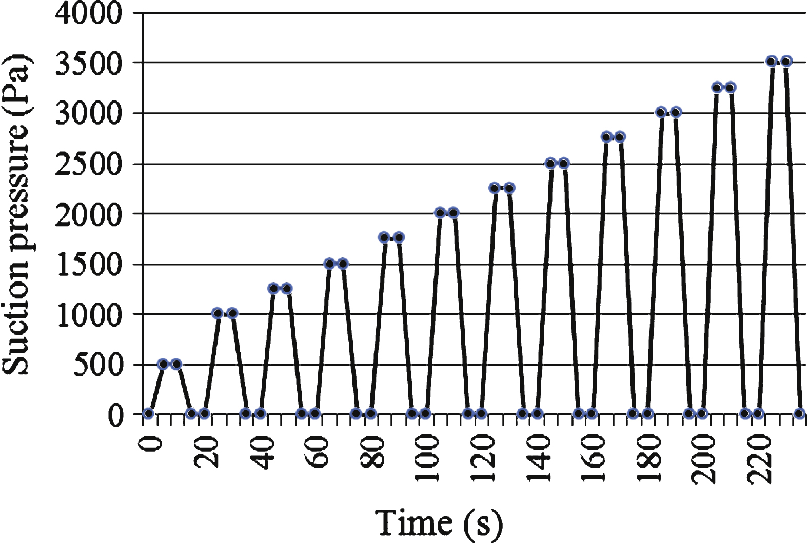
Fig.4
Frontal deflections under wind pressure (2400 Pa) and air infiltration values of P and FP.
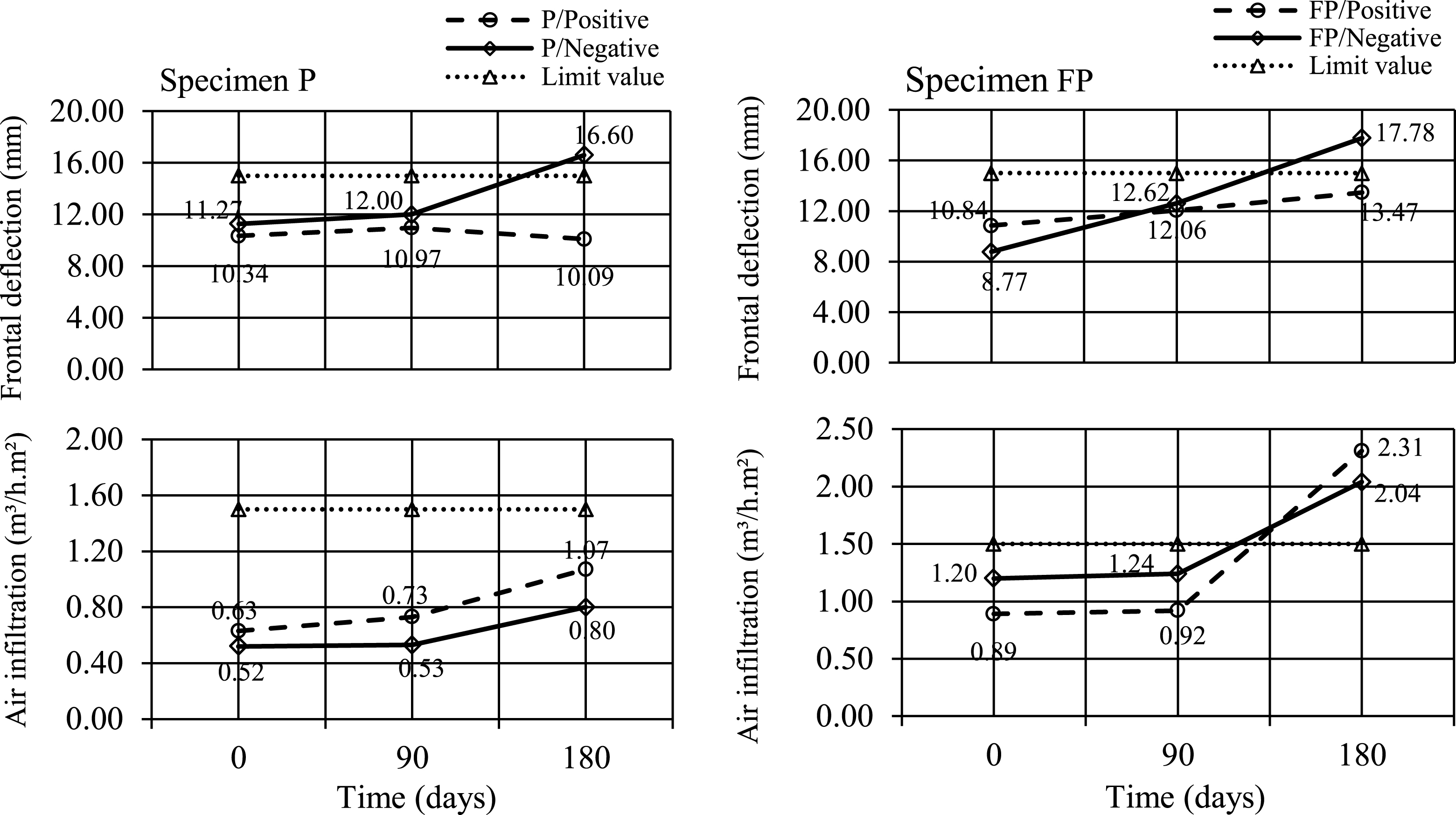
Table 1
Infiltration and structural test results
| Specimen | Time | Load | Air | Air | Water | Frontal deflection | Frontal deflection |
| label | (days) | type | infiltration | infiltration | leakage | value at 2400 Pa (mm) | limit value (mm) |
| value at 600 Pa (m³/m²·h) | limit value (m³/m²·h) | ||||||
| P1 | 0 | positive | 0.63 | 1.50 | No leakage | 10.34 | 15.00 |
| negative | 0.52 | 1.50 | No leakage | 11.27 | 15.00 | ||
| P2 | 90 | positive | 0.73 | 1.50 | No leakage | 10.97 | 15.00 |
| negative | 0.53 | 1.50 | No leakage | 12.00 | 15.00 | ||
| P3 | 180 | positive | 1.07 | 1.50 | No leakage | 10.09 | 15.00 |
| negative | 0.80 | 1.50 | No leakage | 16.60 | 15.00 | ||
| FP1 | 0 | positive | 0.89 | 1.50 | No leakage | 10.84 | 15.00 |
| negative | 1.20 | 1.50 | No leakage | 8.77 | 15.00 | ||
| FP2 | 90 | positive | 0.92 | 1.50 | at W1* | 12.06 | 15.00 |
| negative | 1.24 | 1.50 | at W1* | 12.62 | 15.00 | ||
| FP3 | 180 | positive | 2.31 | 1.50 | at W1* | 13.47 | 15.00 |
| negative | 2.04 | 1.50 | at W1* | 17.78 | 15.00 |
*W1 is the intersection point of A and C units on vertical middle axis of the panel (Fig. 1c).
Note: Highlighted cells show the results that exceeded the limits.
Table 2
Results and performance classification according to the test categories and sequence
| Test Number | Test name | Test standard | Peak test pressure (Pa) | Result | Performance classification | |||||
| P1 | P2 | P3 | FP1 | FP2 | FP3 | |||||
| 1 | 1Air infiltration | TS EN 12153 | 600 | Pass | A4 | A4 | A4 | A4 | A4 | A2 |
| 2 | 2Water penetration (static) | TS EN 12155 | 600 | Pass | R7 | R7 | R7 | R7 | R5 | R5 |
| 3 | 3Water penetration (dynamic) | AAMA 501.1 | 600 | See note4 | No water penetration | at W1* | ||||
| 4 | Wind resistance (design load) | TS EN 12179 | 2400 | See note5 | ** | ** | *** | ** | ** | *** |
| 5 | 1Air infiltration | TS EN 12153 | 600 | Pass | A4 | A4 | A4 | A4 | A3 | A1 |
| 6 | 2Water penetration (static) | TS EN 12155 | 600 | Pass | R7 | R7 | R7 | R7 | R5 | R5 |
| 7 | Seismic resistance | AAMA 501.4 | – | Pass | No deformation | |||||
| 8 | 1Air infiltration | TS EN 12153 | 600 | Pass | A4 | A4 | A4 | A4 | A3 | A1 |
| 9 | 2Water penetration (static) | TS EN 12155 | 600 | Pass | R7 | R7 | R7 | R7 | R5 | R5 |
| 10 | Wind resistance (extreme load) | TS EN 12179 | 3600 | Pass | No deformation | |||||
| 11 | Seismic resistance (static) | AAMA 501.4 | – | Pass | No deformation | |||||
| 12 | 3Fatigue procedure | ETAG 17 | 3500 | Pass | – | – | – | No deformation | ||
1Classification was performed to TS EN 12152 and CWCT.
2Classification was performed to TS EN 12154 and CWCT.
3Applied only on FP1, FP2, and FP3.
4There is no classification or performance requirement for water penetration (dynamic) testing in AAMA standard.
5P1, P2, FP1, and FP2 successfully passed the wind resistance (design load) test requirements in the classification standard of wind resistance testing (TS EN 13166). But specimen P3 and FP3 exceeded the limit value (15 mm) at the peak pressure.
*W1 is the intersection point of A and C units on vertical middle axis of the panel (see Fig. 1c).
**Frontal deflection value <15 mm.
***Frontal deflection value ≥15 mm. For air infiltration test, if exceeded the limit value: 1.5 m3/m2 h at 150 Pa ⇒ class: A1; at 300 Pa ⇒ A2; at 450 Pa ⇒ A3; at 600 Pa ⇒ A4 (TS EN 12152). For water penetration test (static), if exceeded the limit value: 15 mm at 150 Pa ⇒ class: R4; at 300 Pa ⇒ R5; at 450 Pa ⇒ R6; at 600 Pa ⇒ R7 (TS EN 12154).

