
An experimental and numerical simulation study of an active solar wall enhanced with phase change materials
Abstract
Solar walls can be used to increase the overall energy efficiency of a building. Phase Change Materials (PCM) are capable of increasing the effective thermal mass of building elements, thus decreasing the overall energy consumption. Recently, the incorporation of PCM in a solar wall has been proposed, aiming to increase the total energy efficiency of the system. The main scope of this work is to investigate the thermal behaviour of a PCM-enhanced solar wall (PCMESW), using experimental and numerical simulation techniques. A prototype PCMESW is installed in a large-scale test facility and is exposed to dynamically changing climate conditions. A broad range of sensors, used to monitor the time-evolution of several important physical parameters, is employed to assess the dynamic response of the PCMESW. In addition, a Computational Fluid Dynamics tool is used to numerically investigate the thermal behaviour of the PCMESW prototype. Predictions of the developing flow- and thermal-field in the PCMESW’s air cavity are validated by means of comparison with the obtained measurements; in general, good levels of agreement are observed. Results of the numerical simulations may support the design optimization process of innovative PCMESW systems.
1Introduction
Primary energy use in buildings accounts for approximately 40% of the total annual energy consumption and CO2 emissions in the European Union (Balaras et al., 2007). Therefore, energy efficiency of buildings is increasingly becoming a major worldwide energy policy objective. There is a large variety of construction techniques and materials available that can be used to improve the energy efficiency of buildings. Solar walls (SWs) can be used as passive building elements aiming to decrease energy consumption for heating and cooling purposes. In addition, incorporation of Phase Change Materials (PCM) in building elements can be used to increase their thermal inertia. Recently, the use of PCM to increase the effectiveness of a conventional SW has been proposed (Amundarain Suarez et al., 2014); the PCM-enhanced SW can be installed both in new and existing buildings, as a means to improve the total energy efficiency. The main scope of the current work is to investigate the dynamic operational behaviour of an innovative active PCM-enhanced SW, using detailed experimental and numerical simulation techniques.
1.1Solar Wall
A Solar Wall (SW) is essentially a thermal system comprising a glazing panel and a high thermal-mass wall, separated by an air cavity. The orientation of the SW is selected to maximise the incident solar radiation (e.g. Southern orientation in the Northern hemisphere). The temperature of the high thermal mass wall is increased, thus heating the air in the cavity; the heated air flows upwards, due to thermal buoyancy (passive operation, natural convection) or mechanical devices, e.g. fans (active operation, forced convection). Air is allowed to enter and exit the cavity through ventilation openings located in its bottom and top side, respectively. The air ventilation openings can be controlled in order to allow air to enter/exit the cavity either from/to the external (ambient) or internal (indoors) boundary of the system. SW are installed aiming to reduce the overall energy demand for heating and cooling.
1.2Phase change materials
Latent heat storage systems can be used to decrease the overall energy use in buildings; Phase Change Materials (PCM), exhibiting high values of latent heat of melting (or solidification), are extensively used in latent heat storage systems. Use of PCM in building elements has been recently proposed, aiming to increase the indoor thermal comfort (reduction of air temperature peaks, decrease of diurnal indoor temperature fluctuations), decrease the required energy consumption for heating/cooling (reduction of the heating and cooling peak loads) and take advantage of off-peak energy savings (Soares et al., 2013). Latent heat storage by incorporating PCM in building elements is an attractive way to compensate for the limited thermal mass of modern lightweight buildings. Aiming to improve the overall building energy efficiency, PCM can be used in a variety of building elements such as walls (construction units, insulation materials), glazing and shading devices (glazing systems, solar walls), thermally activated constructions or even HVAC systems (Pomianowski et al., 2013).
1.3PCM-enhanced solar wall
When a conventional SW is enhanced with a PCM the total thermal mass of the system is increased. In this case, it is possible to reduce the overall volume of the wall, thus resulting in significant advantages in terms of lower cost and dead load. A number of experimental and theoretical analyses has been conducted to investigate the applicability of using PCM in SW systems (Manz et al., 1997; Weinlaeder et al., 2005; Khalifa & Abbas, 2009; Zalewski et al., 2012; Soares et al, 2013). In a PCM-Enhanced Solar Wall (PCMESW), the large sensible thermal mass of a conventional SW is essentially substituted by the large latent heat exchange, associated with the PCM phase change process.
An innovative technological concept based on this idea has been proposed in a recent European Patent (Amundarain Suarez et al., 2014); the proposed system can be installed either to new or existing (energy retrofitting) buildings. The PCMESW system (Fig. 1) comprises a double glazing layer, a highly reflective solar protection ‘roller blind’ system, a high thermal mass wall which incorporates PCM and an insulation layer located between the PCM-enhanced wall and the indoor environment; an air cavity is formed between the glazing and the wall. In the PCMESW system examined in this work, a commercial macro-encapsulated PCM was used. The temperature range for melting/solidification of the employed PCM was 28–30°C; its latent heat storage capacity was 190 kJ/kg and its mean density was 1510 kg/m3. On the bottom and top sides of the cavity are located air ventilation openings to allow air to enter/exit the cavity either from/to the external (ambient) or internal (indoors) boundary of the system. Air ventilation is assisted by the use of four small electrically driven fans, installed at the bottom of the air cavity; therefore, the examined system is characterized as an ‘active’ device.
This innovative PCMESW system is able to operate in three main operational modes; each mode is further split in two sub-modes, one for ‘daylight’ operation and the other for ‘night-time’ conditions. The general configuration of the PCMESW system in each operational mode is shown in Fig. 2. In operational mode 1, used mainly during the heating season (winter), the PCMESW system operates as a conventional Trombe wall; air is allowed to enter and exit the system only from/to the ‘indoors’ side. During daytime (sub-mode 1-D), the solar protection roller blinds are inactive, thus allowing the incident solar radiation to heat both the air and the PCM-enhanced wall. During night-time (sub-mode 1-N), the solar protection is activated to mitigate heat losses to the ambient. Operational mode 2, also used during the heating season (winter), corresponds to a parietodynamic wall. In this case, ambient air is allowed to enter the system through the bottom inlet vents and, after being heated by the high thermal mass wall, is directed indoors, through the top outlet vents. Similar to operational mode 1, the roller blinds are inactive during daytime (sub-mode 2-D) and are activated during the night (sub-mode 2-N). In operational mode 3, commonly used during the cooling season (summer), the PCMESW system operates as a ventilated facade; air is allowed to enter and exit the system only from/to the ‘ambient’ side. In this case, the solar protection ‘blind’ system is always active, thus preventing the incident solar radiation to reach the high thermal mass wall. In daytime (sub-mode 3-D), the ambient air that enters the system is moving upwards, thus cooling the wall by means of natural ventilation. In night-time (sub-mode 3-N), the wall releases the stored thermal energy to the ambient air moving in the cavity, thus reducing the energy demand for cooling.
Operation of the PCMESW system is optimized by adapting to the varying meteorological conditions. Selection of the appropriate operational mode depends on the prevailing ambient conditions and the desired indoor thermal comfort conditions; changes between operational modes can be made either on predefined time periods (diurnal and annual) or dynamically, using real-time information provided by sensors. Operational modes 1 (Trombe wall) and 2 (parietodynamic wall) are used during the heating season, whereas operational mode 3 (ventilated facade) is used during the cooling season. Selection of the actual operational mode of the PCMESW system can be made either automatically, using appropriate control algorithms, or manually. The different operational modes are set by modifying the position of the air ventilation openings (air can enter or exit either from/to the external (ambient) or the internal (indoors) environment), activation of the solar protection roller blind system (when activated it prevents solar heat flux to reach the high thermal mass wall) and activation of the ventilation fans installed at the bottom of the system (active or passive operation). The configuration of each controllable device for every operational mode and sub-mode available is presented in Table 1.
2Experimental study
As part of the development of the PCMESW system, a scientific and technical assessment of the PCMESW concept was carried out, comprising a full-scale test under real atmospheric conditions. The testing campaign was aimed at providing important information of the energy performance of the system and gaining confidence in the level of integration between different elements in the solar collector system, a significant step before industrialization of the design. For this purpose, a south-oriented part of the building envelope in the experimental research facility Kubik by Tecnalia was modified to house the PCMESW prototype. Although this paper refers mainly to the thermal assessment of the PCMESW development, manufacturability, installation, wear, accuracy of actuators, suitability of fans, wiring and other aspects were also tested in the process.
2.1Layout of the test facility
Kubik by Tecnalia is a full-scale multi-rise building aimed at realistic testing of energy efficient building concepts and architectural systems, providing a fully adaptable environment (internal boundary conditions, HVAC system layout, adaptation of building envelopes, fully customizable building automation and control). It is located in Derio, on the Atlantic coast of Spain, which is characterized by a Cfb climate based on the Koeppen climate classification system (Kottek et al., 2006). The Cfb climate is typical for the majority of Central and Western Europe, including the British Islands and some locations on the Mediterranean coast.
The Kubik building is designed and operated as a test facility to bridge the gap between laboratory testing and full scale deployment and is customized on a case-by-case basis to meet the specific needs of each project. In this particular case, a part of the south-facing curtain wall system was removed to accommodate the PCMESW system (Fig. 3, left). The internal space (room) to which the PCMESW system was attached has an area of 45 m2; thermal comfort measurements for the indoor environment were obtained using a full boundary condition measurement system, comprising temperature measurements at three height levels and a radiant temperature sensor. Heat transfer to other rooms of the building, through internal partitions or floor and roof slabs, was negligible, since the HVAC system of the building provided steady indoor conditions.
The bottom inlet and top outlet vents to the indoor space were located 0.3 m above the floor level and 0.3 m below the ceiling level, respectively. The PCMESW system provided additional heat at the upper area of the indoor space, increasing thermal stratification, however, as this system was conceptualized as a forced (active) ventilation system in which fans are operated whenever the system introduces heat to the building, this eased up the recirculation process through the lower air inlet. In more advanced implementations, a more complex ducting system that may separate the inlet and outlet openings could help in alleviating such issues.
The examined system was heavily instrumented to verify the behaviour of the PCMESW as a passive system (solar thermal collector) and as an adaptive active system (control algorithm). Temperature sensors were located at different heights within the air cavity and the PCM surface of the PCMESW system. These measurements were complemented with the weather station at the Kubik test facility, additional ambient air temperature and radiant temperature sensors installed in the facade, hot wire anemometers in the air cavity and indoor measurements (Fig. 3, right). Temperatures were measured with Pt100 Class-A sensors, with an estimated accuracy of 0.1°C. Solar radiation measurements were obtained by Kipp & Zonen CMP 6 pyranometers. Air velocity measurements were obtained using Schmidt Technology SS-20.500 thermal flow sensors, exhibiting a measurement accuracy of 3% .
2.2Experimental results
The PCMESW system was monitored during the autumn-winter period of 2013–2014. Within this period a complete dataset covering approximately eight weeks was collected. In Fig. 4, representative temperature and solar radiation data are shown. Recorded temperatures at the exposed surface of the PCM-enhanced wall are found to reach peak values of 50–60°C, when the ambient air temperature is far lower (10–20°C), thus demonstrating the potential of the PCMESW system to assist space heating. The high PCM surface temperature values of 50°C clearly suggest that a full phase-change occurred during the tests. The optimal phase change temperature and thickness of PCM was found to be greatly dependent on latitude and local shading; therefore, PCM selection should be based on a local and regional optimization process.
2.3Net output energy for space heating
The net output energy of the PCMESW system, available for space heating, was estimated using the obtained measurements. Empirical correlations were developed, based on a detailed analysis of the measured data, to allow estimation of the maximum daily energy output of the system during a period of one year. As expected, the monthly energy output of the system was found to be highly dependent on the available solar energy for that particular period. In Fig. 5, the estimated monthly energy output for a typical building located in Bilbao (Spain) is presented; a multi-rise residential building with typical construction characteristics of the building stock built in the late 1970s in the area, i.e. uninsulated cavity walls and single glazed fenestration, was considered. During the winter period (November-March), an average monthly energy output of 4 kWh per unit area (m2) of the PCMESW system can be achieved. As expected, larger output energy values for the summer period are obtained; however, this output should be filtered out, according to the actual heating needs of the building during the summer (cooling) period.
3Numerical simulations
An in-depth view of the thermal behaviour of SW in various operational conditions can be obtained by means of numerical simulations; the obtained results may be used to assist the design process of such complex thermal systems (Kolaitis & Founti, 2014). In this work, a detailed numerical simulation study is performed, using the ANSYS-CFX 15.0 Computational Fluid Dynamic (CFD) tool. CFX is a general-purpose CFD tool, capable of simulating complex turbulent, multi-phase, multi-component and reacting flows. The performed time-transient simulations allow investigation of the developing flow- and thermal-fields, aiming to determine the dynamic thermal response of the PCMESW system.
3.1Simulation setup
A simplified geometry of the actual force-ventilated PCMESW prototype system, investigated in the experimental campaign, is simulated. The system consists (from outdoors to indoors) of a double glazing (6 mm and 4 mm glazing panels, separated by a 6 mm thick enclosed air cavity), a 73 mm thick ventilated air cavity and a 17 mm thick PCM layer (c.f. Fig. 1). The dimensions of the system have been determined in order to maintain design compatibility with the structural elements where the PCMESW system will be integrated; the thickness of the PCM layer has been dictated by commercially available macro-encapsulated PCM solutions. The total height of the simulation domain is 1830 mm. A 2D non-uniform Cartesian grid, comprising 51380 elements, is used for the simulations; the gas-phase grid is refined close to the solid boundaries in order to improve the flow resolution in the region of the developing boundary layers (Fig. 6, left). The total simulation time corresponds to a full 24 h period; an adaptive time-step is used, ranging from 15 s to 300 s. The Reynolds-Averaged Navier-Stokes formulation is used to describe turbulent flow phenomena; the Shear Stress Transport turbulence model is employed.
Measurements of the time-varying ambient temperature and solar incident heat flux during a typical 24-hr period (12 October 2013) are used as thermal boundary conditions (Fig. 6, right); these values are imposed on the outer surface of the external glazing that is directly exposed to the environment. The PCM layer on the indoor side of the system was attached to the well-insulated external wall of the Kubik building; adiabatic boundary conditions are used in this case. At the bottom entrance of the air cavity, a constant volumetric air flow (26.3 l/s) is employed, corresponding to the forced ventilation conditions induced by the four fans installed at the air inlet region. A single operational mode (sub-mode 1-D, Trombe wall) is used for the entire duration of the simulation, following experimental practice. Therefore, ambient air temperature measurements are used to estimate the air temperature at the bottom inlet of the system. The thermal behaviour of the commercial PCM, used in the actual PCMESW system, is simulated using the effective specific heat methodology (Kolaitis & Founti, 2013); in this case, the specific heat of the material is artificially modified in the phase change temperature region, in order to account for the PCM’s latent heat of melting/solidification. A range of important PCM thermal properties required for the simulations was unavailable to the authors; plausible assumptions (e.g. thermal radiation emissivity equal to 0.9 and thermal conductivity equal to 0.6 W/mK) have been made for the simulations.
3.2Numerical results
In Fig. 7 (left), CFD predictions for the air cavity and PCM wall surface temperatures are compared to the respective experimental values, obtained at a height of 1600 mm. Numerical results for the PCM surface temperature are found to be slightly higher than the measured values; these discrepancies are attributed mainly to the assumptions used to estimate the (unavailable) thermal properties of the commercial PCM system used in the prototype (e.g. thermal conductivity, emissivity) and the adiabatic boundary conditions used on the ‘indoor’ side. However, a very good quantitative agreement is achieved for the air cavity temperature, suggesting that the CFD code may be effectively used to analyse the characteristics of the flow-field developing in the cavity.
A comparison of the developing velocity and temperature profiles in the air cavity is presented in Fig. 7 (right). The depicted curves correspond to three characteristic positions along the height of the cavity, i.e. 5% , 50% and 95% of the total height, as measured from the bottom inlet; the time instant corresponds to 14:20. Predictions of air velocity and air temperature in the cavity suggest that the mean temperature is increased with increasing height; due to the increased thermal mass of the PCM, higher air velocity and temperature values are observed at the boundary layer developing near the PCM wall. The almost homogeneous velocity profile at the inlet (5% ) is gradually transformed to a highly distorted profile, where high velocities are observed near the wall. A similar behaviour is observed in predictions of the temperature profiles. Near the top outlet of the cavity, the air temperature near the PCM wall is almost 31C higher than the respective temperature close to the inner glazing.
4Conclusions
An innovative solar wall, enhanced with phase change materials, has been investigated, using both experimental and numerical simulation techniques. A prototype PCMESW has been installed in a real-scale testing building and was monitored for eight weeks during the autumn-winter season. The obtained measurements indicated that the potential monthly net output thermal energy of the system, during the winter period in a typical Cfb climate region, may be as high as 4 kWh/m2. Numerical simulations of the prototype device have been also performed, using a CFD tool. Predictions have been found to agree reasonably well with the measured values. CFD results allowed an in-depth view of the developing thermal- and flow-field in the prototype PCMESW.
Acknowledgments
This study has been financially supported by the E.C. in the frame of the FP7 project ‘MeeFS: Multifunctional Energy Efficient Façade System for Building Retrofitting’ (EeB.NMP.2011-3, Grant No. 285411).
Reference
1 | Amundarain Suarez A, Campos Dominguez JM, Chica Paez JA, Meno Iglesias S, Uriarte Arrien A, Garay Martinez R(2014) Passive solar collector module for building envelope., MarchEuropean Patent EP 2520870 B120145 March |
2 | Balaras CA, Gaglia AG, Georgopoulou E, Mirasgedis S, Sarafidis Y, Lalas DP(2007) European residential buildings and empirical assessment of the Hellenic building stock, energy consumption, emissions and potential energy sngsBuilding and Environment42: 12981314 |
3 | Khalifa AJN, Abbas EF(2009) A comparative performance study of some thermal storage materials used for solar space heatingEnergy and Buildings41: 407415 |
4 | Kolaitis DI, Founti MA(2013) Development of a solid reaction kinetics gypsum dehydration model appropriate for CFD simulation of gypsum plasterboard wall asblies exposed to fireFire Safety Journal58: 151159 |
5 | Kolaitis, D. I., & Founti, M. A. (2014). Solar Wall Enhanced with Phase Change Materials: A Detailed Numerical Simulation Study. Proceedings of the 9th Energy Forum on Advanced Building Skins, 28–29 October 2014, Bressanone, Italy, 183–195. |
6 | Kottek M, Grieser J, Beck C, Rudolf B, Rubel F(2006) World Map of the Köppen-Geiger climate classification updatedMeteorological Zeitschrift15: 3259263 |
7 | Manz H, Egolf PW, Suter P, Goetzberger A(1997) TIM-PCM external wall system for solar space heating and daylightingSolar Energy61: 369379 |
8 | Pomianowski M, Heiselberg P, Zhang Y(2013) Review of thermal energy storage technologies based on PCM application in buildingsEnergy and Buildings67: 5669 |
9 | Soares N, Costa JJ, Gaspar AR, Santos P(2013) Review of passive PCM latent heat thermal energy storage systems towards buildings’ energy efficiencyEnergy and Buildings59: 82103 |
10 | Weinlaeder H, Beck A, Fricke J(2005) PCM-façade -panel for daylighting and room heatingSolar Energy78: 177186 |
11 | Zalewski L, Joulin A, Lassue S, Dutil Y, Rousse D(2012) Experimental study of small-scale solar wall integrating phase change materialSolar Energy86: 208219 |
Figures and Tables
Fig.1
Schematic overall layout of the PCMESW system (left) and detailed cross section near the bottom air inlet (right).
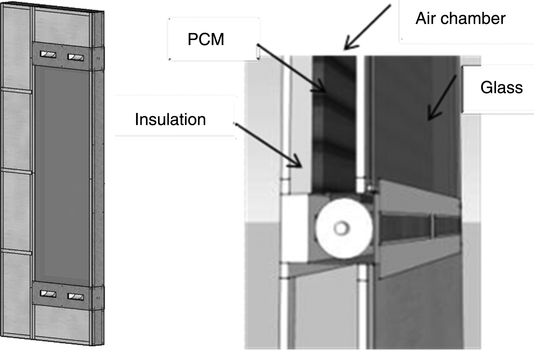
Fig.2
Schematic layout of the three operational modes and six sub-modes.
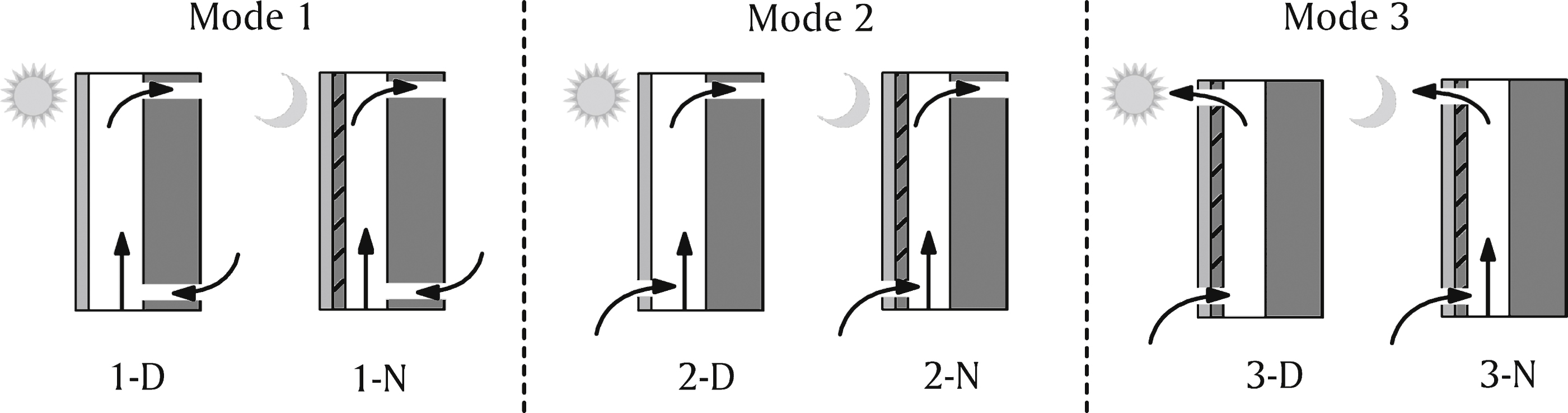
Fig.3
View of the PCMESW system installed in the southern facade of the Kubik building (left) and schematic layout of the installed sensors (right).
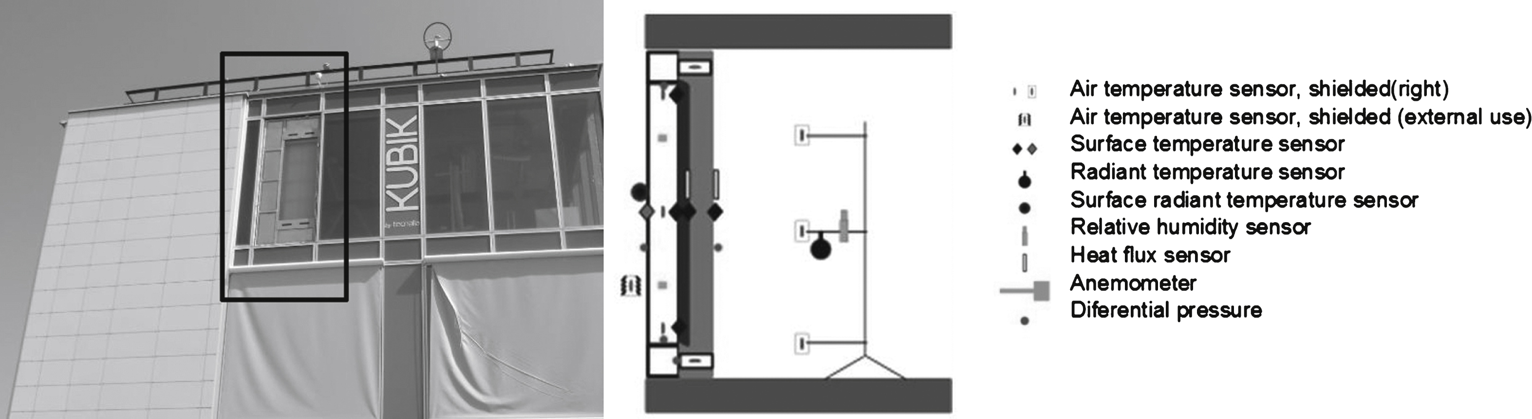
Fig.4
Recorded measurements of temperatures in the PCMESW system (left) and incident solar radiation (right) over a typical 8-day period.
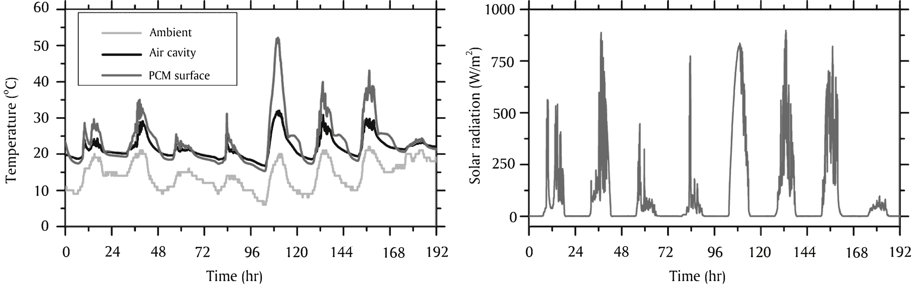
Fig.5
Estimated monthly energy output for space heating, per unit surface area of the PCMESW.
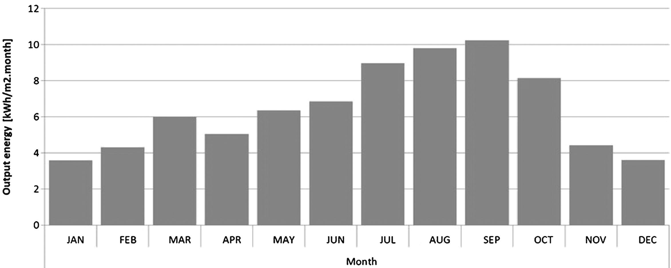
Fig.6
Indicative view of the mesh (left) and time-varying thermal boundary conditions (right).
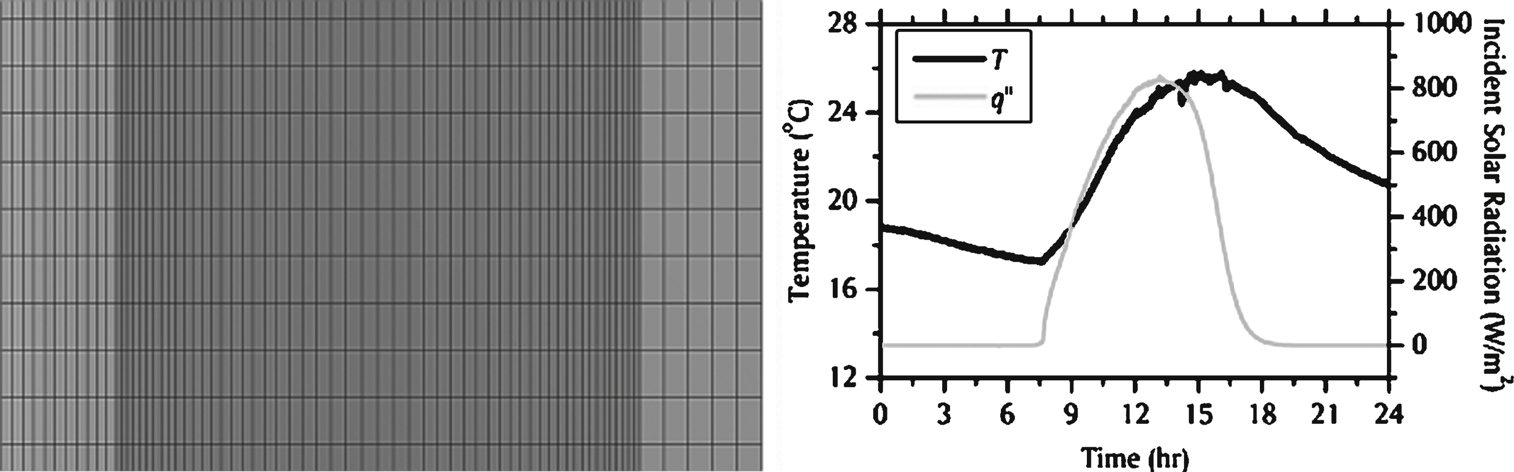
Fig.7
Temporal evolution of air cavity and PCM wall surface temperatures (left) and spatial distribution of air cavity velocities and temperatures at various heights (right).
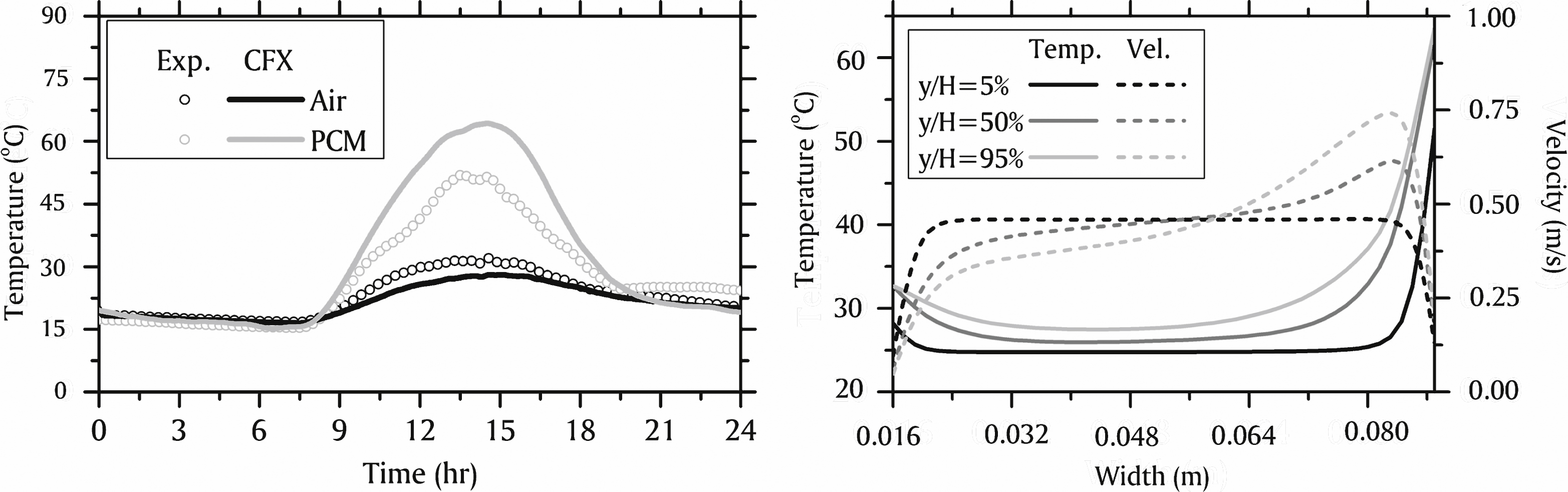
Table 1
System configuration for the three operational modes and six sub-modes
| Operation | Trombe wall | Parietodynamic wall | Ventilated Façade | |||
| Mode | 1 | 2 | 3 | |||
| Sub-Mode | 1-D | 1-N | 2-D | 2-N | 3-D | 3-N |
| Bottom Vent | In | In | Out | Out | Out | Out |
| Top Vent | In | In | In | In | Out | Out |
| Roller blind | Up | Down | Up | Down | Down | Down |
| Ventilation Fan | On | On | On | On | Off | On |

