
Development and construction of a thermoelectric active facade module
Abstract
In order to fulfil the current challenges for the European building sector, building design has diverged into two alternative directions: active technologies and passive design strategies. In the last few years, advanced and responsive building envelope components have represented a promising answer to these challenges. This paper presents the design and construction process of a project that aims to design, build and control the energy performance of an industrial-scale modular active ventilated facade prototype with a new Themoelectric Peltier System (TPS). The TPS is a thermoelectric HVAC heat pump system designed to be located in the building envelope and providing a high comfort level. Trying to optimize the energy performance of the traditional ventilated opaque facade, and make more efficient the energy performance of the TPS, the concept of adaptability has been applied to ventilated opaque facades. The essential research theme is to control the natural phenomena that take place inside the ventilated air cavity of the facade: taking advantage when heat dissipation is needed, and avoiding it when heat losses are not welcome. In order to quantify the previous statements, some facade prototypes are being built in Pamplona (Spain) and their energy performance is going to be analyzed during a year.
1Introduction
The building envelope is the construction element that has the greatest impact on the overall energy consumption of the building (Manioğlu & Yilmaz, 2006). On the one hand, active technologies aim at enhancing the level of sustainability in the built environment via the introduction of innovative technical device. These devices are used for supply of energy from renewable sources or for conversion of resources at higher overall efficiencies (Fabrizio, Corrado, & Filippi, 2010). On the other hand, the term ‘passive’ (Chwieduk, 2003) refers to buildings where the design of construction and shape of the building itself plays more roles in capturing, storing and distributing wind and solar energy, normally with the aim of displacing fossil fuels for space conditioning and lighting (Sadineni, Madala, & Boehm, 2011).
The fact that some of the most well-known producers of technological facade modules and windows have started to develop integrated and modular multifunctional systems (Favoino, Goia, Perino, & Serra, 2014; Hindrichs & Behaling, 2008; Schuster & Mueller, 2007) supports the vision that advanced and responsive building envelope components could represent a promising answer to the challenge posed by the newest energy regulations. These innovative facade concepts (Loonen, Trčka, Cóstola, & Hensen, 2013) are almost ‘self-sufficient’ building skins that show a dynamic behaviour and incorporate different technologies (e.g. decentralized heating/cooling units, heat exchangers, energy supply devices, energy storage, lighting equipments, shading devices, ventilated cavities) aimed at reducing the energy demand of the building, on one side, and at converting energy from renewable sources, on the other.
2Objectives
In this frame, a project called ‘Development, Construction and Analysis of an Active Facade Module with Peltier Cells’ (ThEEn project) is presented, which aims to design an industrial-scale modular active ventilated facade prototype with a new Thermoelectric Peltier System (TPS).
Trying to optimize the energy performance of the traditional ventilated opaque facade and to make more efficient the energy performance of the TPS, the concept of adaptability has been applied to ventilated opaque facades. The focus is a high control of the natural heat transfer phenomena that take place inside the ventilated air gap. The aim is to promote heat dissipation during hot season, and increase heat storage during cold season.
This paper is focused on describing and analysing the design and construction process of the active ventilated facade system that incorporates the TPS. However, no results of the energy monitoring performance are shown because it is still under construction.
3The thermoelectric envelope (ThEEn) project
The objective of the ThEEn project is the characterization of an industrial-scale modular adaptive opaque facade prototype incorporating a Peltier cell (thermoelectricity) driven HVAC system supplied by energy from PV panels.
3.1Adaptive ventilated opaque facade
During last decades the use of a ventilated opaque facade as a solution for residential building envelopes has considerably increased, especially in Mediterranean countries (Marinosci, Strachan, Semprini, & Morini, 2011). A ventilated opaque facade is usually defined as an opaque external layer composed of lightweight and thin cladding, and an opaque internal skin which acts as thermal and acoustic insulation. Between both layers there is an air cavity, drained and always ventilated (no control). No air is transferred from the cavity to the room.
Although it is a really common solution, the ventilated facade is not always the best option, because its energy performance could change heavily according to the climate characteristics and orientation (Mesado, Chiva, Juliá, & Hernández, 2010). That is why its application must be deeply studied before its installation (Giancola, Sanjuan, Blanco, & Heras, 2012). Many studies have been published analyzing the energy performance of a ventilated facade:
• During summer (López, Jensen, Heiselberg, & Ruiz de Adana Santiago, 2012) air flows upwards inside the air gap, due to the action of solar radiation, removing part of the heat loads throughout the facade, thus reducing the heat flux through the indoor environment.
• During cold seasons, when solar radiation tends to be lower, the temperature of the air that leaves the ventilated cavity is usually lower than the indoor air temperature, and the energy balance is negative (Suárez, Sanjuan, Gutiérrez, Pistono, & Blanco, 2012).
Regarding the advantages and disadvantages of the ventilated air cavity, the proposal is to be able to control this ventilation. So as to avoid the heat losses during winter, it is proposed to close the cavity (no ventilation) in order to promote the heat storage in the air cavity, and hence the heat loses are lower. However, during summer the cavity will be opened, thus the heat dissipation is increased.
3.2Thermoelectric Peltier System (TPS)
The facade design incorporates an improved model of the Universidad de Navarra’s Patent (Fig. 1.) (patent number 201101142) of a TPS (Martín-Gómez et al., 2010).
There are many studies that evaluate the behaviour and show the different applications of the Peltier cells and the materials that make them up (Yamashita, 2008, 2011). In our case, thermoelectric technology is used as a cooling or heating system (Rodriguez, Vián, & Astrain, 2008).
The Peltier effect is produced when electric current flows through two different types of semiconductor metals. The current starts the heat transfer from one union to the other: while one union is getting cooler the other starts to heat up. If the direction of the current is changed, the heat transfer direction changes too, hence Peltier cells can be used as heat pumps. From our point of view, in winter it would absorb heat from the exterior air and supply it into the inside room space while in summer, it would absorb heat from the air in the enclosed space and remove it to the outside.
There are some Peltier’s applications in buildings: (Arenas Alonso, Pagola de las Heras, Palacios Hielscher, Rodríguez Pecharromán, & Vázquez Arias, 2007; Cheng, Cheng, Huang, & Liao, 2011; He, Zhou, Hou, Chen, & Ji, 2013; Van Dessel & Foubert, 2010; Xu, Dessel, & Messac, 2007). The vast majority of these applications uses thermoelectric as a way to transmit heat between two environments at different temperatures. Most of them associate the Peltier cells with the transparent part of the facade.
This new HVAC System offers: high precision and reliability, easy installation and reduction of the installation volume.
One of the initial requirements of the project is to drive the TPS by photovoltaic solar panels. However, due to economic reasons it is not possible to incorporate a PV energy supply system at the moment. Nevertheless, there is going to be a quantification of the electricity consumption.
4Design and construction
The project aims to evaluate the possible energy savings and the energy performance of an innovative thermoelectric HVAC system, linked also with ventilation control of the facade air cavity, by means of comparison with a conventional HVAC system and facade system. This article shows the different parameters that have been taken into account not only to design the facade but also to build it.
4.1Site parameters
In order to quantify the previous statements, two identical Prefabricated Building Modules (PBMs) are being built at the School of Architecture in Pamplona (Spain) (Fig. 2).
The fact of having two different PBMs offers the possibility of getting comparative energy and temperature performance data and, therefore, achieves more objective findings.
The two PBMs are located in an isolated place; no buildings can throw any shade on them and they are highly exposed to wind (mainly north direction). However, not only the orientation but also the exact disposal of the PBMs has been studied.
The long side of both PBMs is perfectly orientated south-west, since a simulation made with the software Ecotect ® shows that the south-west facade reaches higher temperatures than the south. So, the facades which are going to be studied are the ones in the most hostile orientation, which means, the south-west.
Despite the fact that the PBMs are located in an isolated site, the software SketchUp ® has been used to simulate the solar movement, and avoid that the two PBMs cast shadow one on the other (Fig. 3).
4.2Building parameters
The differences between these two PBMs (Fig. 4) are:
• PBM 1: It will incorporate a conventional HVAC system (inverter type) and the envelope will be composed by a conventional ventilated opaque facade (no control of the cavity ventilation: always opened).
• PBM 2: It will incorporate the TPS and the air gap ventilation of the opaque facade will be controlled through air dampers on/off (only south-west orientation).
4.2.1Walls parameters
All the sides of the PBMs, except the F2 that incorporates the Peltier system, are composed by always open ventilated facade systems, and highly isolated (Table 1). There is no wall-window that could alter the energy performance data of the opaque facade.
The external layer has a particular shape section mainly because of design reasons (Fig. 5). Nevertheless, this particular shape increases the section of the cavity, which increases the space to heat accumulation during winter. Besides, some air turbulences are expected to take place rising up the heat dissipation during summer.
A steel external layer has been chosen in order to avoid thermal inertia. The colour of this steel sheet is a medium grey, trying to avoid too much solar radiation absorption during summer and too much solar radiation reflection during winter.
4.2.2Cavity parameters
A double height PBM has been designed with the intention to generate natural ventilation in the facade cavities. Besides, the cavity is divided into vertical boxes (Shaft-box) (Oesterle & Lieb, 2001). In this type of division the height of the cavity is not interrupted so it presents a temperature gradient. The air heats up in this space due to the distance between exterior bottom and top openings, which means a better ventilation rate and, consequently, a decrease in the heat gains inside the room during summer.
4.3Active thermoelectric facade parameters
4.3.1Principals
It is important to highlight that the HVAC system is integrated in the ventilated facade. The principal of this new HVAC system is the heat transfer. As a global vision of the process, during hot seasons the TPS extracts the overheating from the inside of the room to the air cavity. On the other hand, during cold seasons the inverse process takes place.
At the same time, in winter the cavity is heated by solar radiation and captured (air cavity ventilation in close position) while during summer it can be effective in extracting the excessive heat from the cavity (air cavity ventilation in open position).
So, in this way, it is expected that the adaptive design of the facade would improve the efficiency of the TPS.
4.3.2Active Peltier facade composition
The composition of the active Peltier Facade is the same as the rest of the walls, but incorporates the following elements:
• Adaptive Facade. Controllable ventilation dampers, installed at the top and at the bottom of the facade. It allows the control of the air cavity ventilation.
• TPS. Consists of a thermo-electric modular equipment with a power of 1000 W. The system incorporates 20 Peltier cells of 51,4 W each. Its dimensions are 1200 mm × 1800 mm × 250 mm, which makes its perfect integration on the facade system possible. The inner layer of the system is a refractory stone of 14 mm.
It must be taken into account that the thickness of the air gap is higher than the ones commonly used for the conventional opaque ventilated facade (6 to 8 to 10 cm). The thickness of the profitable cavity (210 mm) in this case corresponds basically to construction reasons: it is the minimum one that makes the installation of dampers that allow controlling the air gap ventilation possible.
One the one hand, during hot season narrower cavities produce an accentuated stack effect and a stronger air movement which leads to a more effective extraction. On the other hand, in larger cavity depths there is a reduction in the stack effect and the heat transfer towards the interior room increases. This increase could be an advantage for cold seasons, which is the critical season in Pamplona.
4.3.3Expected energy performance
Figure 6 shows the expected energy performance of the active ventilated facade with the TPS.
It must be said that no detail of the Active Peltier Facade can be shown at the moment because of legal reasons.
The set point to open the cavity inlet and outlet takes into account the difference of temperature between the outside (To) and the inside (Ti) ambient. The cavity will be opened when To > Ti and closed when To < Ti.
5Conclusion and future works
The design process of the facade module has been studied deeply. The facade composition and energy performance expectations are already developed. It cannot be denied that the design of this kind of complex building skins is an arduous task, and full of uncertainties.
The next step is to build and monitor the prototypes in order to evaluate their energy behaviour. But, it might be said that the building process has already started. Nowadays, all the civil and services installation works has been done to adapt the site for the PBMs and the frameworks of the modules has been installed (Fig. 8).
Once the building process will be finished, their energy performance is expected to be analysed during an entire year. At the same time, a model is being developed of the two PBMs so as to simulate them not only with EnergyPlus ® but also with ABAQUS®.
The targets of the project are not only to measure the functioning and response capacity of the control of the air cavity ventilation against real situations, as well as its building viability, but also to evaluate the possible benefits and the costs/profit ratio simulating and comparing the system with traditional HVAC installations (validating, as well, the system’s adequacy to different climatological features). Besides, the fact that there is going to be a real prototype allows to assess the viability of commercialization of the system and its possible implementation in other fields.
Acknowledgments
We have to thank the support provided by the BIA2013-46463-R Project. Ministerio de Ciencia e Innovación del Gobierno de España.
Reference
1 | Arenas Alonso A, Pagola de las Heras FL, Palacios Hielscher R, Rodríguez Pecharromán R, Vázquez Arias J(2007) Paramento transparente activo (PTA) en aplicaciones de climatizaciónRE Revista de Edificación101109 |
2 | Cheng T-C, Cheng C-H, Huang Z-Z, Liao G-C(2011) Development of an energy-sng module via combination of solar cells and thermoelectric coolers for green building applicationsEnergy36: 1133140doi:10.1016/j.energy.2010.10.061 |
3 | Chwieduk D(2003) Towards sustainable-energy buildingsApplied Energy76: 1-3211217doi:10.1016/S0306-2619(03)00059-X |
4 | Fabrizio E, Corrado V, Filippi M(2010) A model to design and optimize multi-energy systems in buildings at the design concept stageRenewable Energy35: 3644655doi:10.1016/j.renene.2009.08.012 |
5 | Favoino F, Goia F, Perino M, Serra V(2014) Experimental assessment of the energy performance of an advanced responsive multifunctional façade moduleEnergy and Buildings68: 647659doi:10.1016/j.enbuild.2013.08.066 |
6 | Giancola E, Sanjuan C, Blanco E, Heras MR(2012) Experimental assessment and modelling of the performance of an open joint ventilated façade during actual operating conditions in Mediterranean climateEnergy and Buildings54: 363375doi:10.1016/j.enbuild.2012.07.035 |
7 | He W, Zhou J, Hou J, Chen C, Ji J(2013) Theoretical and experimental investigation on a thermoelectric cooling and heating system driven by solarApplied Energy107: 8997doi:10.1016/j.apenergy.2013.01.055 |
8 | Hindrichs DU, Behaling S(2008) Schüco E façade Profile5: 1837 |
9 | Loonen RCGM, Trčka M, Cóstola D, Hensen JLM(2013) Climate adaptive building shells: State-of-the-art and future challengesRenewable and Sustainable Energy Reviews25: 483493doi:10.1016/j.rser.2013.04.016 |
10 | López FP, Jensen RL, Heiselberg P, Ruiz de Adana Santiago M(2012) Experimental analysis and model validation of an opaque ventilated facadeRenewable and Sustainable Energy Reviews25: 265275doi:10.1016/j.buildenv.2012.03.017 |
11 | Manioğlu G, Yilmaz Z(2006) Economic evaluation of the building envelope and operation period of heating system in terms of thermal comfortEnergy and Buildings38: 3266272doi:10.1016/j.enbuild.2005.06.009 |
12 | Marinosci C, Strachan PA, Semprini G, Morini GL(2011) Empirical validation and modelling of a naturally ventilated rainscreen façade buildingEnergy and Buildings43: 4853863doi:10.1016/j.enbuild.2010.12.005 |
13 | Martín-Gómez, C, Eguaras-Martínez M, Mambrilla-Herrero N, Torres J, Ramos JC, Rivas A(2010) Prototype thermoelectric climate system for its use in residential buildingSantander37th IAHS World Congress on Housing |
14 | Mesado, C., Chiva, S., Juliá, E., & Hernández, L. (2010). Two dimesnional modelling with CFD of the behavior of a ventilated ceramic façade. In J. C. F. Pereira & A. Sequeira (Eds.), 5th European Conference on Computational Fluid Dynamics, ECCOMAS CFD 2010. Lisbon, Portugal. |
15 | Oesterle E, Lieb R-D(2001) Double-Skin Facades: Integrated Planning: Building Physics, Construction, Aerophysics, Air-Conditioning, Economic ViabilityMunichLondon |
16 | Rodriguez, A., Vián, J. G., & Astrain, D. (2008). Design and thermal analysis of the components in a thermoelectric finger icemaker incorporated in a domestic refrigerator. In 6th European Conference on Thermoelectrics. París, Francia. Retrieved from http://ect2008.icmpe.cnrs.fr/Contributions/P1-21-Rodriguez.pdf |
17 | Sadineni SB, Madala S, Boehm RF(2011) Passive building energy sngs: A review of building envelope components158: 36173631doi:10.1016/j.rser.2011.07.014 |
18 | Schuster, H. G., & Mueller, H. F. O. (2007). Interdisciplinary development of a modular façade system with decentralised building services. In 2nd PALENC Conference and 28th AIVC Conference on Building Low Energy Cooling and Advanced Ventilation Technologies in the 21st Century (pp. 908-912). Crete Island, Greece. Retrieved from http://www.inive.org/members area/medias/pdf/Inive/PalencAIVC2007/Volume2/PalencAIVC2007_V2_063.pdf |
19 | Suárez MJ, Sanjuan C, Gutiérrez AJ, Pistono J, Blanco E(2012) Energy evaluation of an horizontal open joint ventilated façadeApplied Thermal Engineering37: 302313doi:10.1016/j.applthermaleng.2011.11.034 |
20 | Van Dessel S, Foubert B(2010) Active thermal insulators: Finite elements modeling and parametric study of thermoelectric modules integrated into a double pane glazing systemEnergy and Buildings42: 711561164doi:10.1016/j.enbuild.2010.02.007 |
21 | Xu X, Van Dessel S, Messac A(2007) Study of the performance of thermoelectric modules for use in active building envelopesBuilding and Environment42: 314891502doi:10.1016/j.buildenv.2005.12.021 |
22 | Yamashita O(2008) Effect of temperature dependence of electrical resistivity on the cooling performance of a single thermoelectric elementApplied Energy85: 1010021014doi:10.1016/j.apenergy.2008.02.011 |
23 | Yamashita O(2011) Effect of interface layer on the cooling performance of a single thermoelementApplied Energy88: 930223029doi:10.1016/j.apenergy.2011.03.017 |
Figures and Tables
Fig.1
Scheme of the original TPS patent.
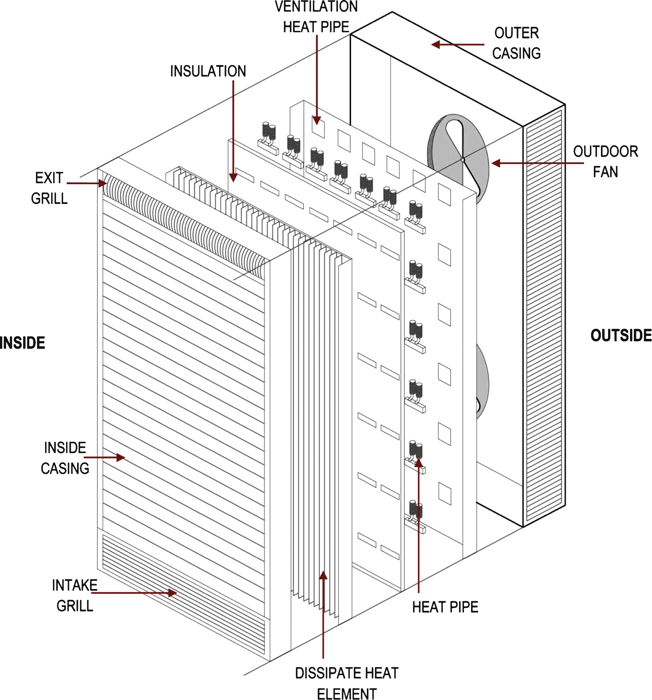
Fig.2
Location of the two PBM at the School of Architecture, Pamplona (Spain).
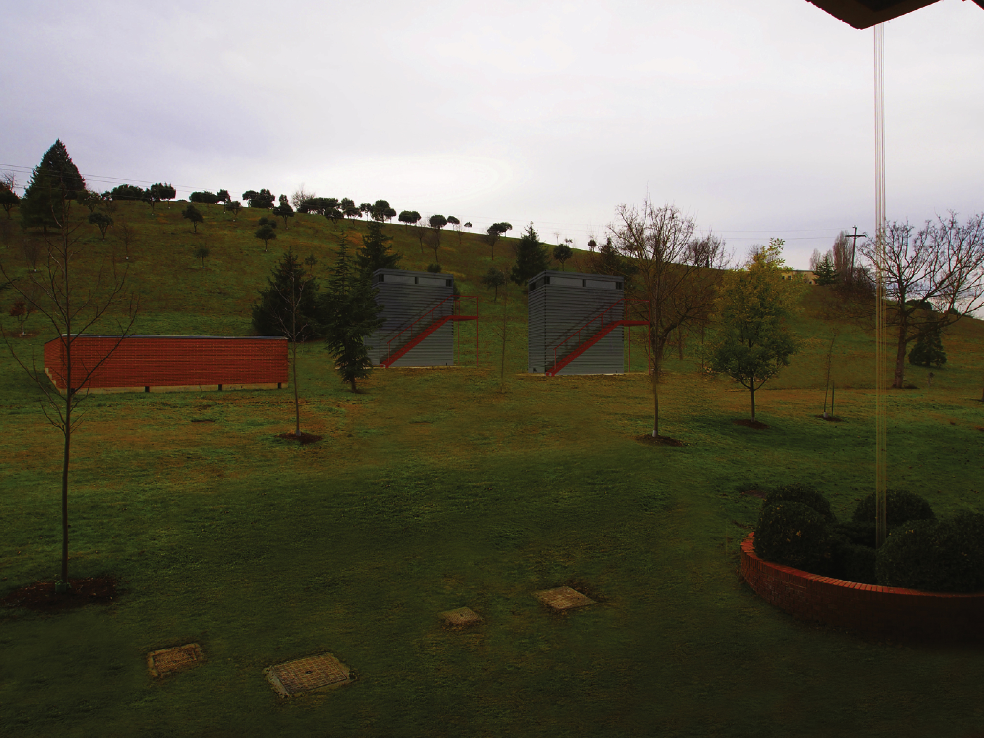
Fig.3
Screen view of the software SketchUp® for September at 12:24 a.m.

Fig.4
Distribution of the PBMs and the type of building walls. F1 (always ventilated facade), F2 (Adaptive Peltier Facade: ventilation control +TPS).
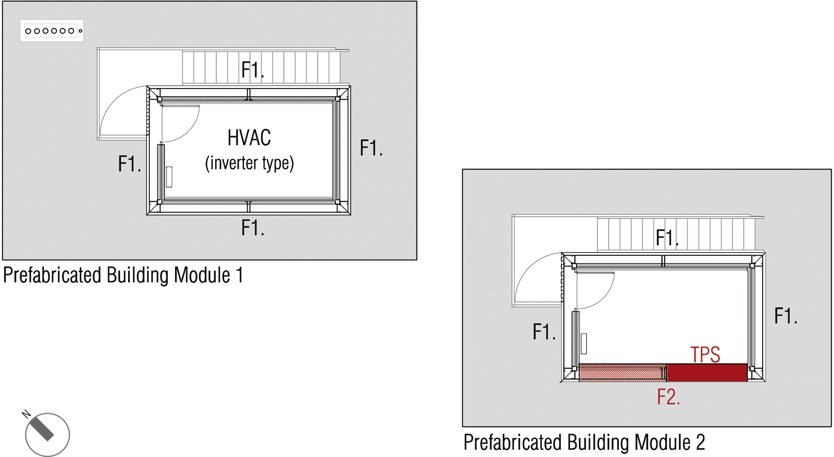
Fig.5
Wall building section.
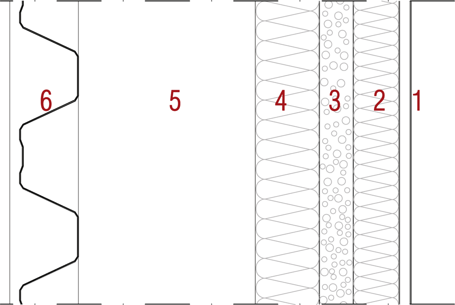
Fig.6
Energy performance during cold season (left) vs. energy performance during hot seasons (right).
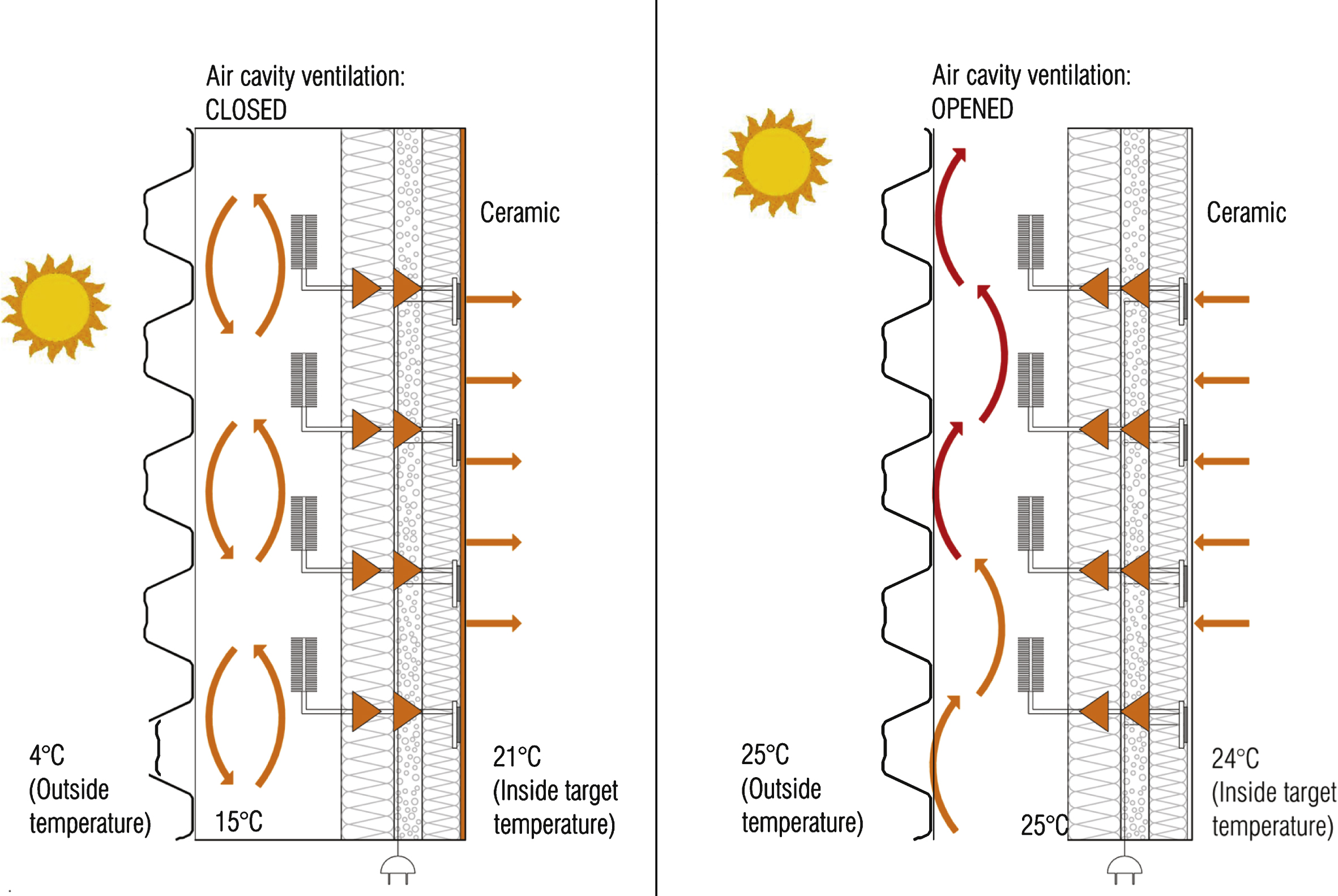
Fig.7
Layout of the measurements system. Front view (a) and section view of the south-west (b) and north-eastfacade (c).
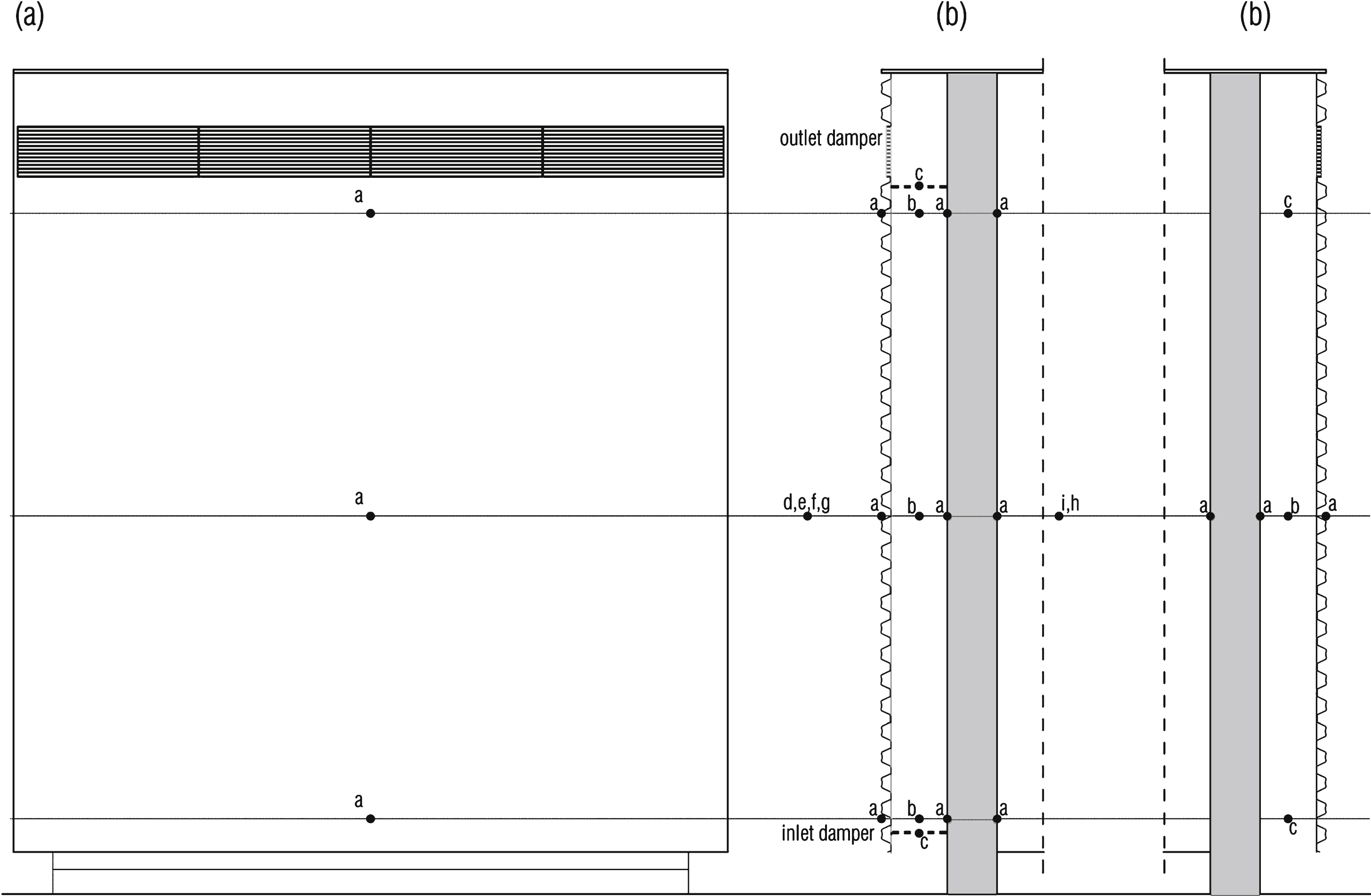
Fig.8
Photo of the PBMs (under construction).
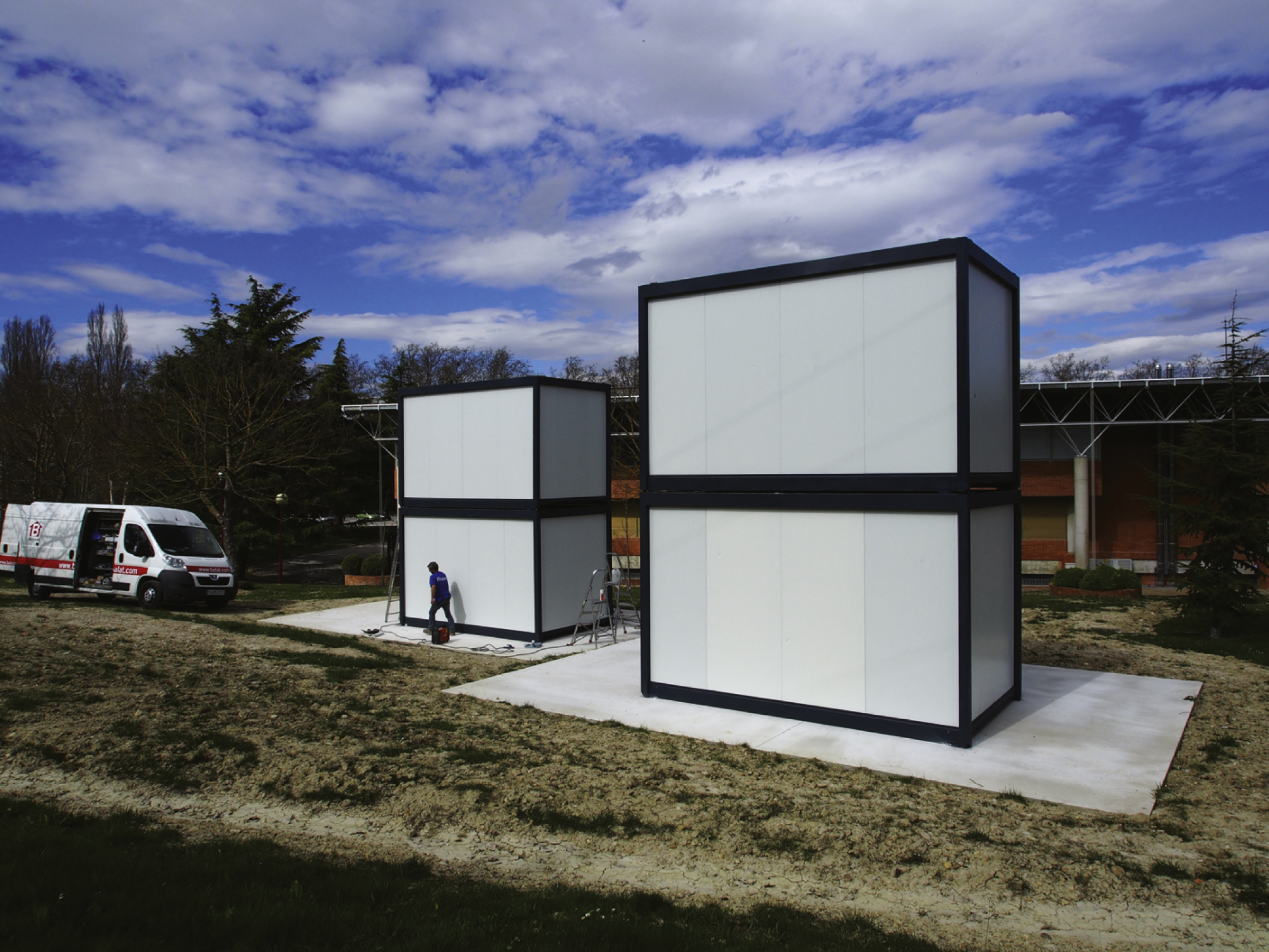
Table 1
Composition and properties of the facade (types F1a and F1b) layers from outside to inside
| Layer | t (mm) | ∧ (W/mK) | R (m2K/W) |
| (6) Trapezoidal steel sheet (open/close) | 1 | – /50 | – /0.00 |
| (5) Air gap (1) (open/close) | 210 | – /0.18 | |
| (4) Panel of rock wool | 65 | 0.034 | 2.03 |
| (3) Thick aluminum sandwich panels with PUR rigid foam core | 35 | 0.023 | 1.13 |
| (2) Panel of rock wool | 46 | 0.035 | 1.43 |
| (1) Laminated gypsum board | 12.5 | 0.250 | 0.05 |
(1)The thickness of the air gap is too wide to calculate its thermal resistance as the coefficient between thickness and thermal conductivity, because of the convective effects that take place inside it.
Table 2
Sensor specifications
| Measurement parameter | Notes | Sensor description | N° | Layout |
| Air flow | (c) Buoyancy driven inside | Ultrasonic anemometer | 8 | PBM1: 2 SW +2 NE |
| the cavity | PBM2: 2 SW +2 NE | |||
| (f) External wind direction and speed | 1 | Outside the PBMs | ||
| Temperature | (d) Shielded External ambient | Platinum resistance thermometer (PRT) | 1 | Outside the PBMs |
| (i) Shielded Internal ambient | 2 | Inside the PBMs | ||
| (b) Mid cavity | 8 | PBM1: 3 SW +1 NE | ||
| PBM2: 3 SW +1 NE | ||||
| (a) Surface | 24 | PBM1: 9 SW +3 NE | ||
| PBM2: 9 SW +3 NE | ||||
| Relative humidity | (g) External ambient | 1 | Outside the PBMs | |
| (h) Internal ambient | 2 | Inside the PBMs | ||
| Global solar radiation | (e) 1 x SW surface | Pyranometer | 1 | Outside the PBMs |

